


 |
Somerset &
Dorset Joint Railway Miscellaneous Signalling Information |
|
Research into the Signalling of the Somerset & Dorset Joint Railway (S&DJR) often yields various minor items of miscellanous information which do not warrant their own separate RailWest page, nor do they necessarily relate specifically to any of the existing RailWest pages on individual S&DJR locations or signalling topics. Nevertheless it is important to ensure that the information is recorded for posterity and available for reference when required, until such time as it may be transferred permanently to another more relevant page. Accordingly this page exists simply to serve as a 'holding pot' for a miscellaneous assortment of such material which may be augmented or relocated during the course of ongoing research. Additional sections on new topics may be added to this page from time to time.
Miscellaneous types of signal arm repeaters
If there was a facing point in advance of a signal, then usually the point would be provided with a 'detector' to ensure that, when the signal was pulled to the 'off' position, the point was indeed closed fully and locked in the correct position. Although the interlocking in the signal-box lever-frame prevented the signal lever from being reversed unless the point lever was in the correct position, without a detector at the point itself there was no guarantee that the point blades were properly closed in their correct position (and bolted by the plunger of a Facing Point Lock (FPL) where appropriate). Traditionally these detectors were purely mechanical devices, but in later years a few examples of electrical detectors were provided, so it is fortunate for research purposes that in later years the S&DJR followed Southern Railway practice and stated on their signal diagrams whether points were mechanically or electrically detected.
Mechanical detectors were made to a variety of designs from different signalling contractors or railway companies and some examples are described in various old publications such as those by H Raynar Wilson [5]. Although most types of detectors were simply inserted into the wire runs from the lever-frames to the signals, some designs involved the use of rodding from the levers as well. The lack of a suitably comprehensive photographic record means that it has not been possible to determine what type(s) were used in S&DJR installations, or at what period, although it is clear that there were variations over the years and especially during the British Railways (BR) era with the differences between BR Southern Region and BR Western Region practice. Therefore the following notes will provide only a generic description of the basic principles of a mechanical detector, but it is hoped to be able to add more details as/when any additional information becomes available.
A mechanical detector contained a horizontal metal slide, positioned parallel to the track; one end was connected to the operating wire from the signal lever, the other end to the wire onward to the signal. At right-angles to that slide would be one or more slides connected to the point mechanism; notches were cut in appropriate places in all the slides, such that the signal wire slide was free to move only when all the point slides were in the correct position. Some detectors might contain two parallel signal slides if there were two signals in rear of the point and the various slides might be notched differently if the two signals read for different routes through the point. It became common in later years to have three point slides - one for the left-hand switch-blade, one for the right-hand switch-blade and one for the FPL plunger - but photographic evidence suggests that many older installations had only one slide for the two switch-blades, especially at points where only one route actually had an associated signal. Some detectors incorporated weighted cranks connected to the signal slides, to ensure that the slides returned to their normal position once the signal lever had been replaced and hence the signal wire went slack.
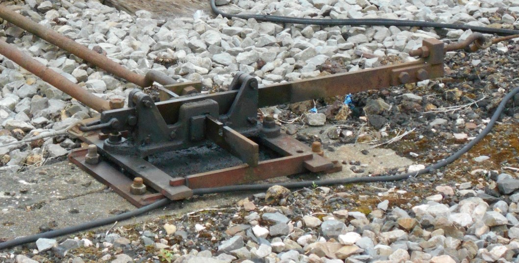 This picture (click for larger image), although of a modern item
of BR(WR) design, illustrates the basic arrangement
for a mechanical detector. The signal slide runs from left
to right and the signal wires are attached at each end; at right-angles to this
slide is a single point slide, with the rod that connects it to the switch-blade. Only when the switch-blade is properly closed will the notch seen
in the slide align correctly with the signal slide and allow that slide to move
for the signal to be cleared. There is a similar notch (out of sight) underneath
the signal slide, which allows the point slide to move only when the signal is
in the 'on' position. To the left of the point slide rod is an additional fixed rod connecting the frame of the detector to
the point to maintain the correct separation distance necessary for accurate operation of the detector.
This picture (click for larger image), although of a modern item
of BR(WR) design, illustrates the basic arrangement
for a mechanical detector. The signal slide runs from left
to right and the signal wires are attached at each end; at right-angles to this
slide is a single point slide, with the rod that connects it to the switch-blade. Only when the switch-blade is properly closed will the notch seen
in the slide align correctly with the signal slide and allow that slide to move
for the signal to be cleared. There is a similar notch (out of sight) underneath
the signal slide, which allows the point slide to move only when the signal is
in the 'on' position. To the left of the point slide rod is an additional fixed rod connecting the frame of the detector to
the point to maintain the correct separation distance necessary for accurate operation of the detector.
An electrical detector was in effect a large multi-pole switch box located at the point, which contained various sets of contacts that would be opened and/or closed as required as the point was moved from normal to reverse or vice-versa. Usually one set of contacts would be connected to the left-hand switch-rail and another set to the right-hand switch-rail, and if the point had a FPL then a third set of contacts would register whether the FPL plunger was 'in' or 'out' (ie the point was locked or unlocked). These contacts would control the operation of an electric lock on the lever(s) of the signal(s) in rear of the points, so that the signalman could not pull a signal lever unless the detector proved the point to be set and locked correctly.
The provision of electrical rather than mechanical detectors was relatively uncommon, except perhaps at large installations with complex signalling, and in many cases appears to have been the result of later alterations which justified or necessitated the additional expense of adding the electrical locking to the lever-frame. In the case of the S&DJR the only known examples of electrical detectors were on the three sets of motor-worked points (Nos 34, 38 and 39) installed at the former Templecombe No 3 Junction during the 1933 layout alterations there, and on the point (No 6) at the north end of the passing-loop at Stalbridge after it had been converted to motor operation in 1955. It is probably not a coincidence that all these examples were on motor-operated points.
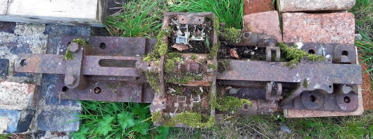 Finally, a detector mystery! The picture
here (click for larger image) shows the remains of a Westinghouse
pattern of combined FPL plunger and electrical detector found in the 1980s
near the former Charlton Marshall Halt.
(The plunger is the long, narrow flat bar and the detector was contained in
the rectangular box positioned across the middle of the plunger.) Now there
was no signalling installation at Charlton Marshall, the
nearest FPLs were at Corfe Mullen Junction and
Blandford (all of which had mechanical detectors), and the nearest
facing point known to have electrical detection was at
Stalbridge - so how did this item come to be at Charlton Marshall? One
theory is that perhaps it fell off a passing scrap train after the
railway had been closed, but apparently the recovery trains for the section
of line closed north of Blandford in 1966 (and hence including Stalbridge)
went northwards via Templecombe and so would not have passed through Charlton
Marshall anyway. An alternative theory therefore is that perhaps it
came from a train recovering materials from the Blandford to
Broadstone section (which remained open
from 1966 to 1968) which would have gone southwards to Broadstone and
therefore passed through Charlton Marshall, and the item might have
come from the former signal department stores at Blandford. As the
provenance of the item is unclear perhaps it is not actually related to the
S&DJR at all, but it would be nice to be able to solve the mystery one day.
Finally, a detector mystery! The picture
here (click for larger image) shows the remains of a Westinghouse
pattern of combined FPL plunger and electrical detector found in the 1980s
near the former Charlton Marshall Halt.
(The plunger is the long, narrow flat bar and the detector was contained in
the rectangular box positioned across the middle of the plunger.) Now there
was no signalling installation at Charlton Marshall, the
nearest FPLs were at Corfe Mullen Junction and
Blandford (all of which had mechanical detectors), and the nearest
facing point known to have electrical detection was at
Stalbridge - so how did this item come to be at Charlton Marshall? One
theory is that perhaps it fell off a passing scrap train after the
railway had been closed, but apparently the recovery trains for the section
of line closed north of Blandford in 1966 (and hence including Stalbridge)
went northwards via Templecombe and so would not have passed through Charlton
Marshall anyway. An alternative theory therefore is that perhaps it
came from a train recovering materials from the Blandford to
Broadstone section (which remained open
from 1966 to 1968) which would have gone southwards to Broadstone and
therefore passed through Charlton Marshall, and the item might have
come from the former signal department stores at Blandford. As the
provenance of the item is unclear perhaps it is not actually related to the
S&DJR at all, but it would be nice to be able to solve the mystery one day.
Note: this section is concerned with the electrical repeaters which were provided in signal-boxes (and some ground-frames) to indicate the status of signal arms and lamps, as well as other items such as track-circuits and motor-operated points. This topic is not related to outdoor 'repeater' signals, which are described in the separate RailWest page on S&DJR signals, nor is it related to the S&DJR's use of Lineman's Boards (described below) which have been described errroneously as 'electric repeaters' by some commentators.
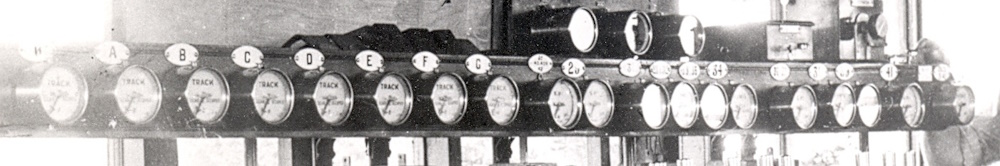
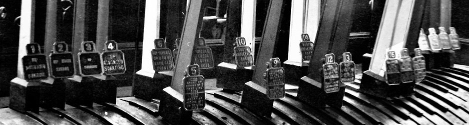
A fine array of Arm, Lamp and Track-Circuit Repeaters in Templecombe Junction signal-box circa-1950
Arm & Lamp Repeaters. It was important that a signalman could be sure that the arms of semaphore signals under his control were in their correct 'on' (stop/caution) or 'off' (proceed) positions depending upon whether the relevant levers in the signal-box lever-frame were in their 'normal' or 'reverse' positions. Similarly it was important to be sure that the oil lamps used to illuminate the signal aspects at night were indeed alight. Although many signals would be within sight of the signal-box, some would not be visible for reasons such as their distance, or the curvature of the line, or some intervening obstruction such as an over-bridge or a building. It became a common practice therefore in due course to provide some form of 'Arm' and/or 'Lamp' electric repeater in the signal-box (and occasionally at manned ground-frames).
Arm repeaters were controlled by a 'circuit controller' (a form of electric switch) attached to the signal arm and the movement of the arm from 'on' to 'off' or vice-versa would cause the indicator to show 'OFF' or 'ON' as appropriate; if the arm failed to move fully from one position to the other than the electric current would be interrupted and the indicator would show 'WRONG'. Lamp repeaters would show simply whether the lamp was alight or not (usually described as the lamp being 'IN' or 'OUT') and these were controlled by a heat-sensitive switch mounted in the top of the lamp casing. If the lamp was alight then the heat from its flame would keep the switch closed and current would flow though the repeater, which would show 'IN', but if the flame went out then the switch would cool down and open to cut the current and the repeater would show 'OUT'.
[Note: sometimes the circuit for lamp repeaters included a relay which, if the current failed because the lamp had gone out, would close a pair of contacts to ring a warning bell in the signal-box to get the signalman's attention. It is not known to what extent this arrangement may have been used on the S&DJR.]
Slot Repeaters. There were some locations on the S&DJR where a signal worked from one signal-box was controlled also from another signal-box by a device known as a 'slot'. There are a couple of instances where signals were recorded as having 'Arm and Slot Repeaters', the 'Slot' repeater enabling the signalman to know when he would be able to clear his signal. However it is not known whether such slot repeaters were in fact electrical repeaters similar to Arm repeaters, or possibly mechanical devices similar to this example.
Repeater 'Groups'. Not every signal arm or lamp had its own individual repeater. Where there were a number of signal arms in close proximity then all their lamps might be 'grouped' on a single lamp repeater, which would show 'OUT' whenever any one of the grouped lamps went out, but it would not give any indication as to which specific lamp had failed (this would become apparent only when the lampman walked out to the relevant group of signals to find the faulty one). Examples of this practice are known to have existed at Midford and Templecombe No 2 Junction. A similar 'grouping' arrangement was used also sometimes for arm repeaters and an example existed at Evercreech Junction North. The advantage of 'grouping' was that it saved money in terms of the installation and maintenance of the number of repeaters and the number of cables from the relevant signals back to the signal-box.
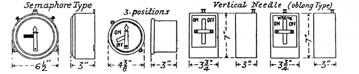
 Repeater Styles. Many different styles of repeater were used by
different signalling contractors and railway companies. Some arm repeaters
took the form of a miniature representation of a signal and its arm, whereas
others used some form of vertical needle moving from side to side between 'ON' or
'OFF' legends. As a very broad generalisation earlier forms of
repeaters tended to be in rectangular wood or metal cases mounted on top of
the instrument shelf above the lever-frame, whereas later models were in
circular brass cases fixed usually to a deep fascia board on the front of the
instrument shelf (as shown in the image at the
start of this section). Where the instrument shelf was an older 'thin' type
then often the circular repeaters were mounted instead on wooden uprights fixed on top of the
shelf (see photo on the right - click for larger image) or even - where space on the
shelf was limited - on boards fixed just below the framed
signal diagram. However it was not unknown for an
individual repeater to be screwed directly to the front of a 'thin' shelf.
Repeater Styles. Many different styles of repeater were used by
different signalling contractors and railway companies. Some arm repeaters
took the form of a miniature representation of a signal and its arm, whereas
others used some form of vertical needle moving from side to side between 'ON' or
'OFF' legends. As a very broad generalisation earlier forms of
repeaters tended to be in rectangular wood or metal cases mounted on top of
the instrument shelf above the lever-frame, whereas later models were in
circular brass cases fixed usually to a deep fascia board on the front of the
instrument shelf (as shown in the image at the
start of this section). Where the instrument shelf was an older 'thin' type
then often the circular repeaters were mounted instead on wooden uprights fixed on top of the
shelf (see photo on the right - click for larger image) or even - where space on the
shelf was limited - on boards fixed just below the framed
signal diagram. However it was not unknown for an
individual repeater to be screwed directly to the front of a 'thin' shelf.
In the absence of suitable photographic records it is unclear what patterns of arm and lamp repeaters were used in earlier S&DJR days, but by the early British Railways (BR) era most appear to have been of the circular brass-cased type favoured by the earlier Southern Railway (SR) and by the 1960s some examples of BR Western Region (BR(WR)) equipment may have been in use. The SR pattern of arm repeaters had red needles on a white background for stop signals, but yellow needles on a black background for distant signals; lamp repeaters had a black needle on a white background. Some arm repeaters had 'S.Rly.' on the background above the needle, whereas others had the word 'SIGNAL' (it is presumed that the latter was simply a later practice) and lamp repeaters had the word 'LIGHT'. At least two examples are known of an arm repeater for a distant signal which had a yellow needle on a white background; these may have been simply replacements that used a repainted 'red' version because the correct yellow/black type was not available.
Track-Circuit Repeaters. Once track-circuits (TC) started to be installed in various places on the S&DJR it became important for the signalman to know whether a TC was occupied or not; although many TCs were well within sight of the signalman, it was not always easy for him to judge from a distance whether (say) a light engine was actually clear of a TC or not, so the provision of a Track-Circuit Repeater in the signal-box was useful. Here again the SR used their circular brass-cased type with a needle (of a bluey-green colour) that moved between 'CLEAR' or 'OCCUPIED' legends on a white background surmounted by the word 'TRACK'; the indicator was controlled by a relay within the TC circuitry.
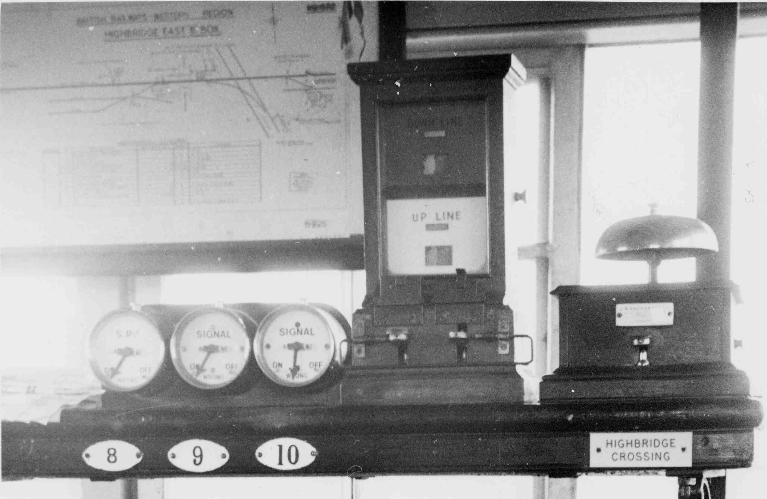
 Another version of TC repeater known to have been used in
two places on the S&DJR (Midford and Glastonbury)
was made by the contractor RE Thompson; this pattern also had a circular
brass case, but was equipped with an upstand to sit on top of the instrument
shelf and surmounted by a flat plate to which a description
label could be attached. It has been described colloquially as a 'banner'
type, because instead of a vertical needle it had a centrally-pivoted broad red rectangular 'arm'
similar to a 'banner repeater' signal. The
arm would be horizontal if the TC was occupied or angled at 45° if the
TC was clear; the words 'CLEAR' and 'OCCUPIED' would be covered or uncovered as
appropriate as the arm moved from horizontal to angled or vice-versa.
The photo here (click for larger image) shows two examples at Midford
circa-1965/66; it is not clear if this type was used by the SR, but it was used
certainly by BR(WR) and it is possible therefore that the
S&DJR examples were installed in fact by BR(WR).
Another version of TC repeater known to have been used in
two places on the S&DJR (Midford and Glastonbury)
was made by the contractor RE Thompson; this pattern also had a circular
brass case, but was equipped with an upstand to sit on top of the instrument
shelf and surmounted by a flat plate to which a description
label could be attached. It has been described colloquially as a 'banner'
type, because instead of a vertical needle it had a centrally-pivoted broad red rectangular 'arm'
similar to a 'banner repeater' signal. The
arm would be horizontal if the TC was occupied or angled at 45° if the
TC was clear; the words 'CLEAR' and 'OCCUPIED' would be covered or uncovered as
appropriate as the arm moved from horizontal to angled or vice-versa.
The photo here (click for larger image) shows two examples at Midford
circa-1965/66; it is not clear if this type was used by the SR, but it was used
certainly by BR(WR) and it is possible therefore that the
S&DJR examples were installed in fact by BR(WR).
Other Repeaters. There is photographic evidence that circular brass-cased needle indicators were installed at Templecombe No 2 Junction in connection with those levers which controlled motor-operated points (at the former Templecombe No 3 Junction) and these had 'NORMAL' and 'REVERSE' legends. (Note: it is unclear whether a similar provision was made at Stalbridge after motor-operated points were installed there in 1955.) Another use for a needle type repeater existed at Midford, where one was linked to a treadle in rear of Midford's Up Outer Home signal to indicate 'TRAIN WAITING' when a train was held at that signal. All of these are believed to have had black needles on a white background. It is quite possible that there may have been other miscellaneous uses for similar 'electric repeaters' on the S&DJR which have escaped record.
List of Repeaters. A List has been complied of all the Electric Repeaters which are known to have existed in S&DJR signal-boxes or ground-frames at various dates. The list is concerned primarily with Arm and Lamp repeaters, but details are included also for repeaters for Track-Circuits, motor-worked Points and other miscellaneous functions (eg 'Train Waiting'). The information relates primarily to the post-1948 British Railways period, but details from earlier years are included where known. The information comes mainly from signal diagrams or locking sketches and a few photographs, but the source material varies in availability and reliability. Although the primary location for electric repeaters was in signal-boxes, it is known that a few existed at some of the manned ground-frames which had signals and details of the latter have been included.
Please Note: the List is provided for general guidance only and must not be regarded as definitive, given the incomplete nature of the source information and the almost total lack of records for the period prior to 1930. It is quite probable that in fact more repeaters may have existed much earlier than are included in the list. Not all the repeaters listed for any one location necessarily existed concurrently, as some were added at later dates and others were removed as a result of layout alterations. The list is intended as a basic summary of all known examples and not a detailed chronological register of additions and removals.
A DRAFT version of the List of Electric Repeaters can be accessed here.
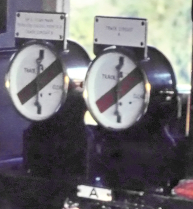
 A Fireman's Call Plunger (FCP) was a push-button
electric switch that
was provided at a signal-post for use by the fireman of a train held at that
signal to remind the signalman of the presence of his train in accordance
with Rule 55. Only one FCP is known to have existed on the S&DJR, which was
at the Down Main Outer Home (signal 2) at Evercreech Junction North box
where it was provided on 10-December-1949. The presence of the FCP was indicated by the provision
of a 'D' sign on the post of the signal. (The signal was on the right-hand
of the double-track line, but the FCP was installed on the left-hand side of
the Down line so that the fireman did not have to risk crossing the tracks
in order to use it.) No photograph of that FCP is known, but given the involvement of
the London Midland & Scottish Railway (LMS) in the S&DJR then it is
possible that the FCP was fitted in a standard free-standing LMS
Fireman's Call Box; a typical example is shown here (click picture for a larger image). Pressing the
plunger would operate a visual indicator in the signal-box and then a
confirmatory audible warning would be given at the call box. There is an
unconfirmed suggestion that a 'D' sign was fitted to the Down Home (No 6) of
the 1946/47 temporary Waterloo Road signal-box, which would imply provision of a FCP at
that location also.
A Fireman's Call Plunger (FCP) was a push-button
electric switch that
was provided at a signal-post for use by the fireman of a train held at that
signal to remind the signalman of the presence of his train in accordance
with Rule 55. Only one FCP is known to have existed on the S&DJR, which was
at the Down Main Outer Home (signal 2) at Evercreech Junction North box
where it was provided on 10-December-1949. The presence of the FCP was indicated by the provision
of a 'D' sign on the post of the signal. (The signal was on the right-hand
of the double-track line, but the FCP was installed on the left-hand side of
the Down line so that the fireman did not have to risk crossing the tracks
in order to use it.) No photograph of that FCP is known, but given the involvement of
the London Midland & Scottish Railway (LMS) in the S&DJR then it is
possible that the FCP was fitted in a standard free-standing LMS
Fireman's Call Box; a typical example is shown here (click picture for a larger image). Pressing the
plunger would operate a visual indicator in the signal-box and then a
confirmatory audible warning would be given at the call box. There is an
unconfirmed suggestion that a 'D' sign was fitted to the Down Home (No 6) of
the 1946/47 temporary Waterloo Road signal-box, which would imply provision of a FCP at
that location also.
The S&DJR would deploy fogsignalmen at its Distant signals in times of fog or falling snow. Most Distant signals on the S&DJR were 'isolated' signals - in other words they were the only signal on their post, rather than being a lower arm beneath a stop signal. Most examples of the latter were in the Highbridge and Wells areas, although prior to the 1930s there had been several in the Radstock and Templecombe areas as well. It would appear to be the case that the non-isolated lower distant arms were not fogsignalled. By its nature, the job of a fogsignalman was not a permanent occupation, but something that would be done as and when required by nominated railway staff, usually members of the Permanent Way Department. Most fogsignalman would be rostered to specific Distant signals, but some would act as Relief men to cover vacancies at any location in their area.
[Note: there is evidence from surviving fogsignalmen rosters for the northern part of the S&DJR main line in the late 1940s that at that time some stop signals were also 'fogged', but the reason for that is not known. The locations listed were:- Bath Junction Up (Branch) Home, Midford Up Outer Home, Evercreech Junction North Down (Main) Home, Templecombe Junction Down Outer Home. One may speculate that possible reasons for those specific signals were because they were either located out-of-sight of the signalman or a long way from the signal-box or because any train failing to stop at the signal was at risk of collision with another train on a converging route. It is possible that some other stop signals were 'fogged' elsewhere on the S&DJR, but no relevant records are known.]
The arrangements for fogsignalling were fairly straightfoward and there does not appear to be much in surviving S&DJR records about any specific requirements at individual locations. However the 1933 edition of the Appendix to the S&DJR Working Time Table (WTT) did include a list of five locations where fogsignalmen would not be provided at the Distant signals:- Moorewood, Henstridge, Pylle, Stourpaine, Spetisbury. The reason for those exemptions was not given, although as the signal-boxes at Stourpaine and Spetisbury appear to have been opened only on rare occasions then their Distant signals would have been normally 'off' anyway. (There was a specific instruction at Stourpaine that no trains were to be passed at that loop during fog or falling snow, but it is not clear whether that instruction was issued to avoid the need for fogsignalmen there, or whether the exemption from fogsignalling was the cause of that instruction.) One may speculate that, as Henstridge and Pylle (after 1929) were neither block posts nor passing-loops, their signals would normally be 'off' for any approaching train; there were level-crossings at both stations, but they saw very little use. It is unclear why Moorewood would have been exempt, but perhaps it was simply more economic to 'switch out' that signal-box rather than to call out two extra men.
The 1933 WTT Appendix also included a list (click here) of 23 locations at which fogsignalmen were employed only at certain times, with both Up and Down Distants being specified in every case. (In fact Bridgwater had only an Up Distant, while at Wells the Up Distants were under stop signals controlled by GWR signal-boxes and possibly therefore not 'fogged' by the SD&DJR anyway. Note also that Writhlington was listed still under its old name of 'Braysdown'.) At all the locations the fogsignalmen were not employed during the night, which might suggest that the specified signal-boxes were 'switched out' during the specified hours, yet the list includes signal-boxes such as Shepton Mallet (which did not have a block switch) and 'key' locations such as Corfe Mullen Junction. So did the S&DJR perhaps only bother with fogsignalman while they were running passenger services, in which case why still provide them at the signal-boxes not included in the list?
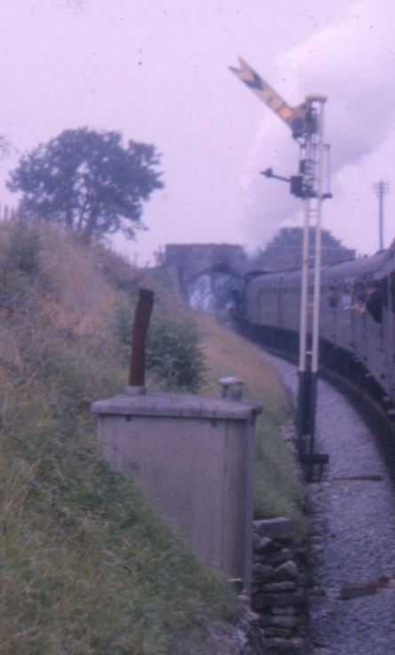 Clearly it was not a pleasant task for fogsignalmen to stand (or sit) for
hours at a time at some remote lineside location, often in atrocious weather
conditions (especially high up on the Mendip Hills on the Bath Extension)
and far from any habitation. Fortunately the Southern Railway, as part of
its wide range of pre-cast concrete products for the railway lineside [6],
manufactured a small concrete 'fog hut' which could be installed by the side
of the track close to the relevant signals. Although utilitarian in design
and appearance, the huts did at least provide the fogsignalmen with a basic
enclosed shelter complete with a small stove and a seat. The photograph on the right here
(click for larger image) shows one such hut located close to the
Shepton Mallet Up Distant signal in 1962; the hut would have been sited with
its door facing towards the signal, so that the fogsignalman could observe
whenever the signal changed from 'on' to 'off' or vice-versa.
Clearly it was not a pleasant task for fogsignalmen to stand (or sit) for
hours at a time at some remote lineside location, often in atrocious weather
conditions (especially high up on the Mendip Hills on the Bath Extension)
and far from any habitation. Fortunately the Southern Railway, as part of
its wide range of pre-cast concrete products for the railway lineside [6],
manufactured a small concrete 'fog hut' which could be installed by the side
of the track close to the relevant signals. Although utilitarian in design
and appearance, the huts did at least provide the fogsignalmen with a basic
enclosed shelter complete with a small stove and a seat. The photograph on the right here
(click for larger image) shows one such hut located close to the
Shepton Mallet Up Distant signal in 1962; the hut would have been sited with
its door facing towards the signal, so that the fogsignalman could observe
whenever the signal changed from 'on' to 'off' or vice-versa.
To be completed....
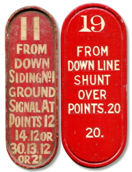
Each lever in a mechanical interlocking frame in a S&DJR signal-box usually would have carried one or more 'labels' with information about that lever. These labels were given various names by different railway companies or signalling contractors (eg 'badges', 'lever leads' etc), but for the purposes of these notes they will be described generically as 'Lever Description Plates' (LDP). For each lever the LDP provided the signalman with three pieces of information:- the lever number, the function of the lever, and the number(s) of any other lever(s) which had to be pulled first in order to release that lever. The latter was known colloquially as the 'pull list' and sometimes could be quite long, maybe with various alternative sequences, depending upon the complexity of the signalling installation. Some railway companies or signalling contractors put all the information on one LDP per lever, other used two or three separate plates. Usually the plates were fixed near the top of the lever (just below the catch-handle), but the S&DJR generally followed the L&SWR/SR practice of placing them near the bottom of the lever (just above the catch-block).
Lever Description Plates in Shepton Mallet
signal-box
Contemporary information suggests that the lever-frames in the original signal-boxes on the 1874 'Bath Extension' were provided by Saxby and Farmer (S&F). It would appear to have been S&F practice at that time to put the lever number on a brass 'badge' attached to the actual lever (probably near the top), but for the lever description to be on a larger brass plate fixed on a long 'label board' mounted lengthways behind the lever-frame. The Bath Chronicle newspaper edition of 23-July-1874 contains a report on the "Opening of the Somerset & Dorset Extension Railway" {sic} which states:-
"..the signalling is effected by Saxby and Farmer's patent levers...the rods of the levers are painted different colours, and are numbered on brass plates to distinguish them. The pointsmen are also assisted by large brass plates fixed behind the row of levers, explanatory of their names and operation..."
From the 1880s onwards, as new signal-boxes were added and older ones replaced, the S&DJR was equipped with lever-frames from Stevens & Sons, which had been adopted as the L&SWR's standard equipment. On the Stevens frames the LDP was a rectangular plate, cast in brass with scalloped corners and a raised rim, with raised brass lettering for the description; the lever number itself was in a smaller rectangular extension on the top edge (see photograph above). Typically the main section measured 3¾" wide x 3¼" high, with the upper extension being 2" x 1½". [In later years there were examples of plates with sign-written painted legends, possibly as a result of old plates being 'ground down' and re-used.] These brass plates had two parallel pairs of 'lugs' on their rear, by which they were bolted to their levers. On a push-pull lever the plate would be longer than usual, in order to accommodate the separate 'Push' and 'Pull' function descriptions (see for example levers 5 and 9 in the photo above). It would appear that in most cases the background of each plate was painted black, but a few examples survive in which the background matched the colour of the lever.
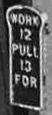 Any 'pull lists' were provided on separate 'pull plates' fixed near the top of their
lever. These plates were usually smaller and narrower, with a curved 'swell' top but no scalloped corners, and fixed by means of a single rear 'lug' only.
Usually there was the word 'PULL' (or sometimes 'WORK') at the top, then the list of numbers, then the word 'FOR', the legend in effect being a prefix to
the wording on the main description plate. If a 'pull list' included a push-pull lever, then it had to state also whether that lever had to be 'pushed' or 'pulled', as can been
seen in the example here (Shapwick lever 14). On 'push-pull' levers the plates would be longer, as there would be separate pull lists for the 'PUSH' and
'PULL' functions, and some of these plates may have had a second rear 'lug' nearer the bottom. Some
pull-plates with several alternative 'pull lists' could reach a long way down the lever - click
here to see a rather poor image of a typical S&DJR example (Binegar lever 22) with three alternative pull sequences.
Any 'pull lists' were provided on separate 'pull plates' fixed near the top of their
lever. These plates were usually smaller and narrower, with a curved 'swell' top but no scalloped corners, and fixed by means of a single rear 'lug' only.
Usually there was the word 'PULL' (or sometimes 'WORK') at the top, then the list of numbers, then the word 'FOR', the legend in effect being a prefix to
the wording on the main description plate. If a 'pull list' included a push-pull lever, then it had to state also whether that lever had to be 'pushed' or 'pulled', as can been
seen in the example here (Shapwick lever 14). On 'push-pull' levers the plates would be longer, as there would be separate pull lists for the 'PUSH' and
'PULL' functions, and some of these plates may have had a second rear 'lug' nearer the bottom. Some
pull-plates with several alternative 'pull lists' could reach a long way down the lever - click
here to see a rather poor image of a typical S&DJR example (Binegar lever 22) with three alternative pull sequences.
 Although the L&SWR style was probably predominant on the S&DJR for many years, an
exception occurred when the Bridgwater Railway
was opened in 1890. The new signal-boxes at Edington Junction and Bridgwater, and the ground-frame at
Cossington, were supplied by Dutton & Company of Worcester with their own style of frame. Dutton
fitted their own design of oval brass 'badges' with engraved legends,
placed near the top of the lever; these were made in a variety of styles,
but the examples illustrated here (not of S&DJR origin) are
similar to those seen in photographic evidence of Edington Junction in 1890. However the signal-box and lever-frame
at Bridgwater were replaced about 1910-15 and photographs of its replacement
frame show the normal L&SWR style plates. A similar change probably took
place when the lever-frame at Edington Junction was replaced circa-1915.
It is unclear what may have happened at Cossington, although by the
mid-1930s most of its levers were spare anyway.
Although the L&SWR style was probably predominant on the S&DJR for many years, an
exception occurred when the Bridgwater Railway
was opened in 1890. The new signal-boxes at Edington Junction and Bridgwater, and the ground-frame at
Cossington, were supplied by Dutton & Company of Worcester with their own style of frame. Dutton
fitted their own design of oval brass 'badges' with engraved legends,
placed near the top of the lever; these were made in a variety of styles,
but the examples illustrated here (not of S&DJR origin) are
similar to those seen in photographic evidence of Edington Junction in 1890. However the signal-box and lever-frame
at Bridgwater were replaced about 1910-15 and photographs of its replacement
frame show the normal L&SWR style plates. A similar change probably took
place when the lever-frame at Edington Junction was replaced circa-1915.
It is unclear what may have happened at Cossington, although by the
mid-1930s most of its levers were spare anyway.
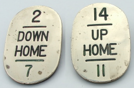
 During the 1920s the Southern Railway
(SR) adopted a new style of LDP, with all the information being placed on a
single plate near the bottom of the lever (although at least one lever-frame
is known where the plates were fixed near the top of their levers).
These new plates were cast-iron, oval in shape, with a single lug on the back
for bolting to the lever. Each plate was painted the same colour as its
lever with the legend sign-written in white paint (black paint on white or yellow
plates); on levers with more than one colour the plate was usually painted to match
the colour of the bottom half of the lever. Any 'spare' levers had a white LDP which bore merely the lever
number; it is unclear what had happened in L&SWR days with levers which were
'spare' initially (rather than became spare later), but circumstantial
evidence would suggest that no LDP was provided.
During the 1920s the Southern Railway
(SR) adopted a new style of LDP, with all the information being placed on a
single plate near the bottom of the lever (although at least one lever-frame
is known where the plates were fixed near the top of their levers).
These new plates were cast-iron, oval in shape, with a single lug on the back
for bolting to the lever. Each plate was painted the same colour as its
lever with the legend sign-written in white paint (black paint on white or yellow
plates); on levers with more than one colour the plate was usually painted to match
the colour of the bottom half of the lever. Any 'spare' levers had a white LDP which bore merely the lever
number; it is unclear what had happened in L&SWR days with levers which were
'spare' initially (rather than became spare later), but circumstantial
evidence would suggest that no LDP was provided.
There were two variants of the SR design, as illustrated here by these non-S&DJR examples. The left-hand plate has a raised rim, whereas the right-hand plate is slightly wider (8¾" x 3½") without a rim, but instead has a narrow 'gutter' inset a short distance from its edge. The narrow type originated from the Westinghouse Brake & Signal Company, but it may have been based on an earlier design by Saxby & Farmer. Westinghouse also produced the wider design in due course, but most of the latter were made by Thomas Holcroft & Sons and had large 'TH&S' and 'SR' cast in the back, whereas later Westinghouse examples had much smaller 'WB&SCo'. Photographic evidence suggests that most S&DJR examples were of the wider style, but certainly the narrow type were fitted at Sturminster Newton.
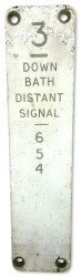 During the British Railways era much of the S&DJR came under the control of the Western Region (WR), who used
their own pattern of LDP. This consisted of a narrow rectangular cast-iron
back-plate, with a single lug at the rear for bolting to the lever, to which
a rectangular face-plate (7¾" x 1¾") was screwed in each corner. The face-plates were made from 'Traffolyte', a phenolic plastic
sandwich of a thick black layer between two thin white layers; the legend was engraved into the white face to a depth sufficient that the black showed
through as a contrast. The face-plate '3' illustrated here came from
Evercreech Junction South box. Unlike the L&SWR or SR, the WR always fixed its LDPs
near the top of the lever.
During the British Railways era much of the S&DJR came under the control of the Western Region (WR), who used
their own pattern of LDP. This consisted of a narrow rectangular cast-iron
back-plate, with a single lug at the rear for bolting to the lever, to which
a rectangular face-plate (7¾" x 1¾") was screwed in each corner. The face-plates were made from 'Traffolyte', a phenolic plastic
sandwich of a thick black layer between two thin white layers; the legend was engraved into the white face to a depth sufficient that the black showed
through as a contrast. The face-plate '3' illustrated here came from
Evercreech Junction South box. Unlike the L&SWR or SR, the WR always fixed its LDPs
near the top of the lever.
There is only one S&DJR location (Glastonbury) where it is known that a complete replacement set of WR-pattern LDPs were fitted and photographs show that its push-pull levers had two LDPs, one near the top of the lever for the PULL function and one near the bottom for the PUSH function. (It is possible of course that there were other S&DJR signal-boxes with full WR replacement sets which are unrecorded.) Most of the known usage of WR-pattern LDPs on the S&DJR was simply the occasional two or three fitted as a result of some minor change to a lever-frame, where they looked totally incongruous at the opposite ends of their levers from all the remaining L&SWR or SR style LDPs. Such changes could be seen for example at Midford, Midsomer Norton and Evercreech Junction South.
It is likely that few, if any, S&DJR signal-boxes retained their full original set of LPDs until closure, as there were usually occasional small alterations that would require at least one or two plates being replaced. The function of a lever might be changed, an interlocking alteration might affect the pull-list of other levers, or perhaps simply a plate had broken. Although the replacement plates might be of the same general pattern as the originals, various minor differences in style could become obvious on closer inspection. Many lever-frames received a complete replacement set of SR-style LDPs during their life-time (eg Wellow, Shillingstone, West Pennard), whereas others retained the L&SWR type until closure.
The S&DJR also had a number of ground-frames (GF) at various locations. Based on the limited photographic evidence it would appear that these were provided with LDPs in a similar style and fashion to the signal-boxes, albeit perhaps with some minor variations. For example, the 1907 GF at Midsomer Norton had typical L&SWR-style plates, whilst the 1933 GF at Horsington Crossing (at Templecombe Junction) had SR-style plates which appear to have been a shorter variant. The 1952 'Colliery' GF at Midsomer Norton had WR-style plates, but apparently with a white legend on a dark background (possibly painted metal rather than engraved 'Traffolyte').
In the event of a problem with any of the equipment at a signal-box the signalman would need to call for the assistance of the local Signal or Telegraph Lineman as relevant. In the early days before the widespread provision of railway telephone circuits to signal-boxes, stations, works depots etc, one method was to hang some form of 'board' outside the signal-box to catch the attention of any passing lineman or other railway staff. It is not known exactly when the S&DJR adopted this practice, but certainly in 1877 the London & South Western Railway (L&SWR) issued an Instruction for the use of a black board at their signal-box at Templecombe and by late 1891 a red board was being used by the S&DJR at Templecombe No 2 Junction box. The Somerset & Dorset Railway Trust has in its collection (reference S62) a red board which came from Stalbridge; this is wooden, approximately 21"x15"x¾" with a large V-shaped hanging bracket on its rear, and is painted red all over on both faces (click here for a photograph). It is presumed therefore that the earlier boards were also rectangular.
[Note: For comparison with other railway companies, it is recorded [1] that the Midland Railway used oval boards, blue on one face and black on the other. The Great Western Railway used separate round 'S' and diamond 'T' cast-iron plates; black background with white letter and rim on the front, white background with red letter and rim on the rear.]
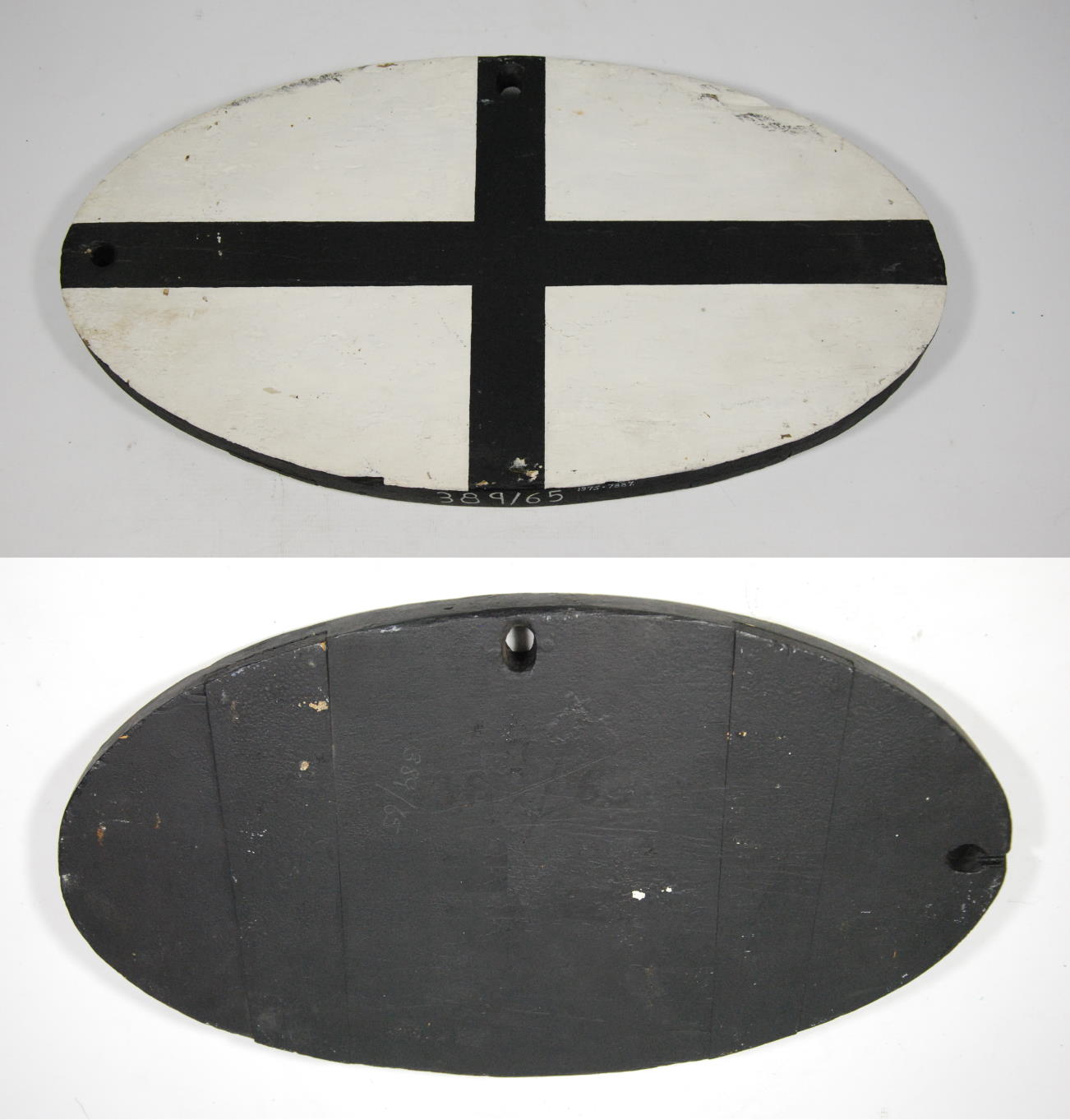
Specific instructions about the use of 'linemen's boards' do not appear in surviving copies of the Appendix to the S&DJR Working Time Table (WTT) until the 1905 edition, and these deal specifically with boards that were oval in shape (geometrically an ellipse); a surviving example of those boards measures 18"x10¼". Each board was painted white on one face and black on the other, and could be hung (by means of a hole in one end and another hole midway along one side) with its long axis either vertical or horizontal. Although the earlier rectangular boards appear to have been hung outside the signal-box only in the event of a problem, the oval boards were always on display and conveyed their 'message' as follows:-
The WTT Appendix instructions (click here to see a copy) included the oval boards in a section about 'Electric Repeaters' (specifically signal arm repeaters); this has lead some commentators to confusingly describe the boards themselves as 'electric repeaters', which clearly they were not (actual S&DJR Electric Repeaters are described above). Although the instructions illustrate the boards with plain white or black faces (and continued to do so as late as the 1914 edition), it is clear from photographic evidence that by 1900 at least there was a black cross on the white face. The origin and purpose of this is unknown, but perhaps it was provided to ease the task - when briefly sighting the white face of a board against the light-coloured paintwork of a timber signal-box wall from a passing train - of deciding whether it was hanging vertical or horizontal? Curiously there appears to have been no equivalent white cross on the black face.
 The oval boards related to the status of electrical
apparatus, which were the responsibility of the Telegraph linemen. The late
Robin Atthill wrote [2] that the red rectangular boards
were used to call the Signal linemen (who dealt with mechanical signalling
equipment), implying that the use of red boards continued concurrently with
the oval boards. However it should be noted that the 1905 S&DJR WTT Appendix
mentions the red board at Templecombe No 2 Junction box
specifically in the context of a failure of the block instruments working to
the boxes at the L&SWR station, which surely would have been the
responsibility of the Telegraph lineman. Whereas the oval boards were hung
outside of a signal-box permanently, it would seem that the red boards were
displayed only in the event of a fault, so there is no known photographic
evidence of them in use. Given that the signal-box at
Stalbridge was
replaced in 1903 (S&DJR Signal Instruction 166),
by which time the oval boards were in use, as its red board (shown here) survived long
enough to be preserved then it does seem likely that it continued in use as
well for some years thereafter.
The oval boards related to the status of electrical
apparatus, which were the responsibility of the Telegraph linemen. The late
Robin Atthill wrote [2] that the red rectangular boards
were used to call the Signal linemen (who dealt with mechanical signalling
equipment), implying that the use of red boards continued concurrently with
the oval boards. However it should be noted that the 1905 S&DJR WTT Appendix
mentions the red board at Templecombe No 2 Junction box
specifically in the context of a failure of the block instruments working to
the boxes at the L&SWR station, which surely would have been the
responsibility of the Telegraph lineman. Whereas the oval boards were hung
outside of a signal-box permanently, it would seem that the red boards were
displayed only in the event of a fault, so there is no known photographic
evidence of them in use. Given that the signal-box at
Stalbridge was
replaced in 1903 (S&DJR Signal Instruction 166),
by which time the oval boards were in use, as its red board (shown here) survived long
enough to be preserved then it does seem likely that it continued in use as
well for some years thereafter.
 With the eventual spread of telephone circuits across the S&DJR the
oval boards appear to have fallen into disuse by the 1920s, although one
might have thought that they would have still had a use if the telephones
failed. It would seem that at many places the boards were just left hanging outside their signal-boxes
until eventually they were 'acquired' for preservation or simply rotted
away. In some photographs of S&DJR signal-boxes it is possible to make out
the outline on the front wall of where the board used to hang. One visitor
to the line found boards at Binegar,
Masbury and Winsor Hill, Robin
Atthill found others still in place in 1965 at Bason Bridge,
Evercreech New and
Henstridge, and David Milton apparently found one at
Glastonbury in
the grass in the station yard! Thanks to Robin Atthill (with the assistance
of the Stationmaster at Stalbridge) the Henstridge board survives in the National Railway Museum
collection (inventory reference 1975-7887) and is shown here (click picture
for larger image).
With the eventual spread of telephone circuits across the S&DJR the
oval boards appear to have fallen into disuse by the 1920s, although one
might have thought that they would have still had a use if the telephones
failed. It would seem that at many places the boards were just left hanging outside their signal-boxes
until eventually they were 'acquired' for preservation or simply rotted
away. In some photographs of S&DJR signal-boxes it is possible to make out
the outline on the front wall of where the board used to hang. One visitor
to the line found boards at Binegar,
Masbury and Winsor Hill, Robin
Atthill found others still in place in 1965 at Bason Bridge,
Evercreech New and
Henstridge, and David Milton apparently found one at
Glastonbury in
the grass in the station yard! Thanks to Robin Atthill (with the assistance
of the Stationmaster at Stalbridge) the Henstridge board survives in the National Railway Museum
collection (inventory reference 1975-7887) and is shown here (click picture
for larger image).
'Line Clear' & 'Tablet Out' Releases
Over time it became the practice for a signal which controls entry into a block section (the 'section signal') to be interlocked with the relevant block working equipment, so that the signal can not be cleared until the train has been accepted by the signalman at the far end of the section. The methods for providing such controls varied between single-track and double-track lines, and the extent of coverage varied according to the practices of the various pre-nationalisation railway companies and any upgrades in later years. In the case of the S&DJR the arrangements for single-track and double-track sections are described below in the notes on 'Tablet Out' and 'Line Clear' releases respectively. A later safety refinement of the LC release was the addition of a 'One Pull Only' control whereby, once the signalman had obtained the necessary acceptance and pulled the section signal lever, after the lever had been replaced it could not be pulled again until the signalman had obtained a new release. Although no 'One Pull Only' controls are known to have existed on the S&DJR prior to BR days, they are recorded in one signal box in the 1960s (see below).
'Tablet Out' Release. In the case of single-lines the former London & South Western Railway (L&SWR) made widespread use of 'tablet out' releases on section signals for lines worked by the Electric Train Tablet (ETT) system, whereby a signalman could not pull the lever for a section signal until he had obtained a tablet for that section from his ETT instrument. It is often presumed that a similar practice was applied to the S&DJR, but research would suggest that there was no universal provision on the S&DJR until a fairly late date, perhaps not until the early British Railways period, and unfortunately the overall situation is far from clear.
Minute 7318 of the S&DJR Officers' meeting on 19-July-1921 recorded that the Traffic Superintendent reported that "...on the sections of main line between Templecombe and Shillingstone, and Corfe Mullen and Broadstone and Wimborne, the starting signals are not interlocked with the tablet apparatus..." and it was considered desirable to provide this at an estimated cost of £154. (A copy of the signal diagram for Shillingstone dated 1907 lists 'tablet out' releases for the 'short' section to Stourpaine and the 'long' section to Blandford, but not for the section to Sturminster Newton; this may reflect an upgrade that was done purely in connection with the opening of Stourpaine signal-box in 1905, implying that previously there had been no 'tablet out' release for the original Shillingstone - Blandford section.) Two years later Minute 7564 of the S&DJR Officers' meeting on 29-October-1923 recorded that the Traffic Superintendent reported that "...the total cost of providing interlocking between the tablet instruments and starting signals for the whole of the branch lines on the Joint Committee's Railway, which are not so fitted, would be £282...", so it was recommended that "...the work be carried out at ...Glastonbury and Edington at an estimated cost of £108, and the question as to the other places was deferred for further enquiries"; that recommendation was agreed at a subsequent meeting on 16-April-1924 (Minute 7609). Reference to various S&DJR and BR signal diagrams would suggest that places such as Shapwick and West Pennard still did not have 'tablet out' releases in the 1930s and may not have received them until the early 1950s, so it is possible that the addition of such releases coincided with the replacement of ETT working by Electric Key Token (EKT) working at those locations circa-1952/53.
It is the practice for levers in a signal-box which are released by another signal-box to be identified by a 4" white band painted around the middle of the lever, which would include levers for signals controlled by the withdrawal of a tablet or key token. Theoretically therefore one could tell if a signal-box had 'tablet out' releases or not by examining a photograph of its lever-frame (if one was available) for the presence or absence of such white bands, but unfortunately that does not appear to be a reliable guide for S&DJR signal-boxes. For example, in the 1960s white bands could be found at Glastonbury and Shapwick, but not at Midford, Sturminster Newton or Templecombe Junction even though 'tablet out' releases were known to have existed at the latter three locations. Here again it is possible that the provision of the white bands at Glastonbury and Shapwick coincided with the introduction of EKT working by BR Western Region.
Much of the information relating to 'tablet out' releases at individual signal-boxes has come from copies of signal diagrams and other associated records. There are a few examples of diagrams which state 'Tablet instruments with Sykes interlocking', or words to that effect. Some L&SWR locations had Sykes 'Indicator Lock' instruments on the instrument shelf to do the physical locking of the section signal lever and controlled electrically by the ETT machine, but no S&DJR example has been found yet. However there are S&DJR drawings which show that, where Tyer's No 3 ETT instruments were fitted, the interlocking was done by mechanical linkage from the drawer and side-handle of the ETT machine to a Sykes-type lock on the signal lever, so maybe that was the meaning of the 'Sykes interlocking' comment? Where Tyer's No 6 ETT instruments were fitted then the interlocking appears to have been achieved by a normal electric lock attached to the lever tail and released by electrical contacts within the ETT instrument and a similar method would have been used with EKT instruments.
The provision of a 'tablet out' (or 'token out') release was listed usually in the Electrical Locking table for a signal-box, which for most S&DJR locations formed part of the actual signal-box diagram. (Click here for more information about the style and content of S&DJR signal diagrams.) Under British Standard 376 the provision of a 'tablet out' or 'token out' release is indicated on a signal diagram by an arrow symbol drawn across the post of the relevant signal and inclined to the right. This symbol does not appear to have been applied to any S&DJR signal diagram until the BR period, and both Southern Region and Western Region diagrams have examples with the arrow inclined to the right and examples with the arrow inclined to the left.
[Note: the 'arrow' symbol is often used as a form of shorthand (to save writing "released by tablet out" in full) by compilers of signal-box diagram sketches for historical reference (such as can be found in RailWest) and its use in any such sketch should not be taken as evidence that it existed on the real-life diagram. In a S&DJR context one should be wary of instances where the symbol may have been used on diagrams for older versions of a signal-box installation without verification by the compiler that a 'tablet out' release did in fact exist at that time.]
'Line Clear' Release. On double-track lines the basic principle would be that the lever operating the 'section signal' would be locked by an electric lock, which would be released only when the indicator on the block instrument for the section ahead was in the 'Line Clear' position (showing that the signalman at the next signal-box in advance had accepted the train). By contrast to its practice for single-line sections, unlike some other railway companies (eg the Great Western Railway (GWR)), the L&SWR had relatively few installations on double-track lines where there were 'Line Clear' (LC) controls on the section signal, other than in some important locations with a high level of traffic.
Any information about the provision of LC releases at individual S&DJR signal-boxes has been gleaned from surviving copies of signal diagrams and other associated records. A LC release was listed usually in the Electrical Locking table for a signal-box, which for most S&DJR locations formed part of the actual signal-box diagram. (Click here for more information about the style and content of S&DJR signal diagrams.) Under British Standard 376 the provision of a LC release is indicated on a signal diagram by the letter 'B' drawn on the signal post, but this symbol does not appear to have been applied to any S&DJR signal diagram other than those drawn by the Western Region during the BR period.
[Note: the 'B' symbol is used sometimes as a form of shorthand (to save writing "released by line clear" in full) by compilers of signal-box diagram sketches for historical reference (such as can be found in RailWest) and its use in any such sketch should not be taken as evidence that it existed on the real-life diagram.]
An assessment of available S&DJR records indicates that, as a general rule, LC releases were not provided at S&DJR signal-boxes which controlled the entrance to double-track sections, so at most locations the section signals were 'free' and could be cleared by the signalman at any time. One known exception was the Up Advanced Starting signal at Wellow, although it would appear that release was related to the operation of the Sykes instrument at Midford rather than 'Line Clear' on the block telegraph instrument; it is not known when this control was installed, but certainly it was in use by 1930. As part of the 1933 alterations at Templecombe No 2 Junction (to abolish the No 3 Junction signal-box) LC releases were installed on the Down line only on the section signals at Wincanton (Down Advanced Starting signal 4), Cole (Down Advanced Starting signal 4) and Evercreech Junction South (Down Advanced Starting signal 6), the latter two being necessary as both Wincanton and Cole boxes could 'switch out'; however the reason for making those additions is unknown.
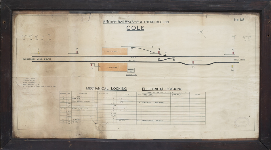 In 1960 at
Cole the crossover at the north end of the station
and its Up Advanced Starting signal (11) were abolished, after which its Up
Starting signal (12) become the section signal for the Up line; by
the time that the box was abolished in 1965 its signal-diagram (click
for larger image) listed a LC release on the Up section signal (12) as well as the Down section
signal (4). The same diagram also recorded 'One Pull' controls on both the
section signals. Sadly no information is available as to when or why a LC
release was added on the Up section signal (it did not
exist in 1948, nor did either 'One Pull' control), nor whether similar additions ever took
place on the Up line at Wincanton or Templecombe No 2 Junction, although a BR(WR) diagram copy for Wincanton which dates from after the
closure of Cole shows no such addition. The various LC releases described above were the only known S&DJR examples.
In 1960 at
Cole the crossover at the north end of the station
and its Up Advanced Starting signal (11) were abolished, after which its Up
Starting signal (12) become the section signal for the Up line; by
the time that the box was abolished in 1965 its signal-diagram (click
for larger image) listed a LC release on the Up section signal (12) as well as the Down section
signal (4). The same diagram also recorded 'One Pull' controls on both the
section signals. Sadly no information is available as to when or why a LC
release was added on the Up section signal (it did not
exist in 1948, nor did either 'One Pull' control), nor whether similar additions ever took
place on the Up line at Wincanton or Templecombe No 2 Junction, although a BR(WR) diagram copy for Wincanton which dates from after the
closure of Cole shows no such addition. The various LC releases described above were the only known S&DJR examples.
In the days when most goods trains were 'unfitted' - in other words, they did not have continuous automatic brakes - there was always a risk that, if a goods train was stopped at a signal on an uphill gradient, when the signal was cleared and the train re-started any accidental 'jerk' might cause a coupling to break and allow the rear portion of the train to run out-of-control back down the line. To guard against such a situation it was a common practice on double-track lines to insert an unworked spring-loaded trailing catch-point some distance in rear of the Home signal, set back sufficiently far that any train stopped at the Home would not be standing over the catch-point. Such catch-points would be held normally 'open' by their spring, but would be pushed 'closed' by the wheels of any train running over them in the normal direction of travel; once the train had passed the catch-point then it would spring back open again, ready to derail any runaway. Although perhaps such catch-points might be considered more a Permanent Way than signalling item, as they did appear sometimes on signal diagrams and/or be mentioned in Signal Instructions or similar notices it seems worthwhile to include some information about them on this page.
Such 'runaway' catch-points were provided on the Down line at Midsomer Norton and Moorewood, and on the Up line at Masbury and Winsor Hill. At Midsomer Norton it would appear that the catch-point was originally 390 yards in rear of the Down Home; the situation at Moorewood is unclear, as the various records are conflicting, and nothing is known about the original locations at Masbury and Winsor Hill. Minute 7786 of the S&D Officer's Conference on 23-April-1926 recorded a decision that "...in consequence of the increased loading of goods trains...owing to the use of the 2-8-0 type of engine..." the catch-points at Midsomer Norton, Masbury and Winsor Hill would be set back to give a clearance of no less than 500 yards at a cost of £33; there was no mention of Moorewood, so perhaps the catch-point there was already at a suitable distance. The revised distances from the relevant Home signals were listed in the 1933 edition of the S&D WTT Appendix as being 520 yards at Masbury, 525 yards at Moorewood, and 540 yards at Midsomer Norton and Winsor Hill.
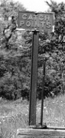 The relevant Instructions
for each location stated that
"...the position is indicated by the word 'Switch' painted in black letters on the small
Signal-box covering the handle of the Runaway Catch Points..."
(except that at Moorewood the term used was simply 'box' rather than
'Signal-box'), but it not known why it was decided necessary to cover
the hand-lever by what must have been little more than a small wooden 'hut'. It
is presumed that at least part of the hut must have been painted in a
light colour in order to provide contrast with the word 'SWITCH' in black.
Unfortunately no known photographs exist of any of the four huts, all of which
were removed at unknown dates after which the position of the catch-points was
identified by a small 'CATCH POINTS' notice on a post sited next to the
hand-lever (the photo shows the notice at Masbury). As far as is known all four runaway catch-points remained in use
until the relevant parts of the S&DJR closed to all traffic in 1966.
The relevant Instructions
for each location stated that
"...the position is indicated by the word 'Switch' painted in black letters on the small
Signal-box covering the handle of the Runaway Catch Points..."
(except that at Moorewood the term used was simply 'box' rather than
'Signal-box'), but it not known why it was decided necessary to cover
the hand-lever by what must have been little more than a small wooden 'hut'. It
is presumed that at least part of the hut must have been painted in a
light colour in order to provide contrast with the word 'SWITCH' in black.
Unfortunately no known photographs exist of any of the four huts, all of which
were removed at unknown dates after which the position of the catch-points was
identified by a small 'CATCH POINTS' notice on a post sited next to the
hand-lever (the photo shows the notice at Masbury). As far as is known all four runaway catch-points remained in use
until the relevant parts of the S&DJR closed to all traffic in 1966.
A 'Signal Arm Replacer' was a device provided to automatically return a semaphore signal arm to the 'on' (danger) position after the passage of a train, even if the signalman had not yet replaced the relevant lever to its normal position. The concept of an automatic arm replacer appears to have arisen (at least in part) as a result of some early accidents where, as the result of the failure of a signalman to replace a signal to 'danger' sufficiently promptly after the passage of a train, a following train got a false 'clear' indication and passed the signal incorrectly and collided with the rear of the preceding train. However these devices did not get widespread use and they appear to have been confined mainly to locations where particular problems had been experienced and/or were anticipated.
The only known example of a signal arm replacer on the S&DJR was fitted to the Up Advanced Starting signal (6) at Wellow, possibly because this was the signal controlling the entrance to the block section to Midford and was out of sight of the signalman. The date of installation is not known (sadly such devices appear not to have been recorded on signal-box diagrams) and the only known reference to it is in the 1933 Appendix to the S&DJR Working Time Table, where it was the sole entry in a Table of "Signals which are placed to danger automatically on the passing of trains". It was removed at some date after the issue of Supplement 3 to the 1933 WTT Appendix on 3-March-1937, as the subsequent Supplement 4 dated 7-May-1945 deleted the entry, so it is possible that it was abolished when the Up Advanced Starting was renewed in 1942 (presumed to be the occasion of the change from a lower-quadrant to an upper-quadrant arm).
There were a number of different designs of signal arm replacer [4] and it is not known which type was used at Wellow, but it may have been one of the Sykes versions (click here for more details). These were electro-mechanical devices which were inserted into the 'down-rod' which connected a signal arm to its weight lever, such that the down-rod was in two parts connected together by the replacer. An arm replacer might be regarded as a form of 'clutch' that was normally engaged, but could be disengaged by an electric current applied to its internal electro-magnetic coil. When the signalman pulled the relevant lever to clear the signal then the weight lever at the signal would push up the down-rod and the signal arm would be lowered as usual. (Note: it is believed that this type of arm replacer was used only with lower-quadrant signal arms.) After a train had passed the signal it would then pass over a treadle installed in the track some distance in advance of the signal, which would send an electric current to the arm replacer coil; this would cause the 'clutch' to disengage and therefore disconnect the two parts of the down-rod, so the signal arm was now free to return to the 'on' position because of the weight of its spectacle plate casting. When the signalman returned the lever to its normal position the weight lever on the signal would drop down and the 'clutch' in the arm replacer would re-engage the two parts of the down-rod.
As can be seen here, one version of signal arm replacer made by Sykes was circular in shape, which led to such devices being given the nickname 'banjo'. There is a description of the use of this device in an article [7] in the February 1905 edition of the Railway Magazine (click here to see an extract from page 127). It is unfortunate perhaps that the article refers specifically to 'banjo signals', in a context which implies that they were a replacement for the 'Disc & Crossbar' signals used previously by the Somerset & Dorset Railway in the 1860s, when in fact the 'banjo' was simply a device attached to a normal semaphore signal. Nevertheless the article is useful as evidence of the existence of at least one signal arm replacer on the S&DJR by 1905 (if not earlier).
It could be said that the 'Whitaker Apparatus' was not really an item of 'signalling equipment' as such, but as it played an important part in the daily working of the single-line sections of the S&DJR's main line it seems appropriate to include some information about it on this page. The history of this equipment has been described in detail by the late Peter Cattermole [3], so these notes will cover simply some basic information about the actual usage of the apparatus.
Alfred Whitaker was the S&DJR's Locomotive Superintendent at Highbridge from 1889 until 1911. In 1905 he patented (British Patent No 861 of 1905) an apparatus to enable the automatic exchange of single-line tablets with a passing locomotive at a much higher speed (usually a maximum of 40 MPH) than was permitted for a manual exchange by a signalman. The apparatus consisted of two separate items, a large 'standard' which was fixed at the side of the track by the cess and a smaller 'exchanger' which was attached to the side of the cab or tender of the engine. The actual tablets to be exchanged were put into leather pouches attached to small steel hoops, similar to but smaller than those which were used for manual transfer.
The original version of the normal 'exchanger' lineside standard had two long arms, one above the other. At the end of the upper arm there was a large pair of metal jaws, which formed the 'receiver' to catch a pouch from the passing locomotive. The lower arm was the 'deliverer', at the end of which there was a bracket to hold the pouch which was to be collected by the locomotive. Normally the arms would be parallel to the track in order not to obstruct the loading gauge of passing trains, but they would be swung at right-angles towards the track by the signalman when required for an exchange. Once the exchange had been completed the arms would swing back automatically away from the track. In a later version the lower arm was shorter and attached to the underneath of the upper arm part of the way between the main post and the jaws at the end.
The equipment on a locomotive comprised a 'receiver' jaws with a 'deliverer' holder immediately behind and above it, attached to a metal slide-bar by which it could be pushed out from, or pulled back to, the side of the cab/tender. Normally the apparatus would be kept close to the cab/tender side in order not to foul any lineside structures, but the fireman would put the pouch in its holder and push the apparatus outwards as they approached the lineside standard. (The usual practice was to do this when passing the relevant distant signal and the photograph here shows this operation on a Down train approaching Shillingstone.) Once the exchange had taken place the fireman would withdraw the apparatus, remove the pouch, and read the wording on the tablet to the driver to confirm that it was the correct tablet for entry into the next block section.
Although the prototype apparatus was tested at Highbridge and (apparently) on the Bridgwater Branch, when it was introduced into service in 1905 it was installed only on the S&DJR's 'main line' from Bath (Single Line) Junction to Wimborne Loop and Broadstone (L&SWR). (It is possible that the level of service demand on the branches west of Evercreech Junction was not deemed enough to justify the cost of any improvements.) Each passing-loop on the single-line sections was provided with two 'exchanger' standards, one adjacent to the Up loop and one adjacent to the Down loop. Generally these would be placed close to the signal-box for convenience of access by the signalman, although the precise location varied depending upon the actual layout at each station. This arrangement existed therefore at Stalbridge, Sturminster Newton, Shillingstone and Stourpaine (until its closure in 1951).
At locations where there was a change between single and double track working then a different arrangement was used; a 'pick-up' post with a deliverer arm only would be positioned for trains entering the single-line section, whilst a 'set-down' post with a receiver arm only would be positioned for trains leaving the single-line section. This arrangement existed therefore at Bath (Single Line) Junction, Midford, Templecombe (No 2) Junction, Blandford, Corfe Mullen Junction, Wimborne Loop and Broadstone (see Note below). It will be seen therefore that, contrary to the impression sometimes given in descriptions of the Whitaker apparatus, the S&DJR's use of the combined 'exchanger' standard was actually less than that of separate 'pick-up' and 'set-down' posts. An example of a 'pick-up' post survives in the collection of the Somerset & Dorset Railway Trust and can be seen here.
[Note: although Table D1 of the 1960 BR(SR) Western Section Sectional Appendix states that Broadstone had a combined deliverer+receiver on each side of the line, photographic evidence from that period proves that it was just a deliverer for Up trains and a receiver for Down trains as would be expected for its layout.]
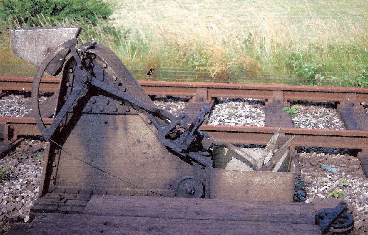 At Templecombe (No 2) Junction the setting-down post for trains coming off the
single-line from Stalbridge had to be located in the 'six foot' between the
Up and Down Main lines. A normal standard would have been
an obstruction to passing main line trains, so a special version - known
colloquially as the 'falling man' - was used instead as shown here (click picture for a larger image). This
post was hinged near the bottom so that normally it lay on the ground
out of the way, but it was raised to vertical by the signalman when required
for use; the action of catching the pouch from the passing locomotive would
cause the apparatus to fall back down again. A similar 'falling man' was
installed at Corfe Mullen Junction for use by Up
trains coming off the line from Wimborne Loop, but after
the cessation of regular passenger services on that line it was moved to
Bath Junction in 1924 in connection with
signalling alterations there.
At Templecombe (No 2) Junction the setting-down post for trains coming off the
single-line from Stalbridge had to be located in the 'six foot' between the
Up and Down Main lines. A normal standard would have been
an obstruction to passing main line trains, so a special version - known
colloquially as the 'falling man' - was used instead as shown here (click picture for a larger image). This
post was hinged near the bottom so that normally it lay on the ground
out of the way, but it was raised to vertical by the signalman when required
for use; the action of catching the pouch from the passing locomotive would
cause the apparatus to fall back down again. A similar 'falling man' was
installed at Corfe Mullen Junction for use by Up
trains coming off the line from Wimborne Loop, but after
the cessation of regular passenger services on that line it was moved to
Bath Junction in 1924 in connection with
signalling alterations there.
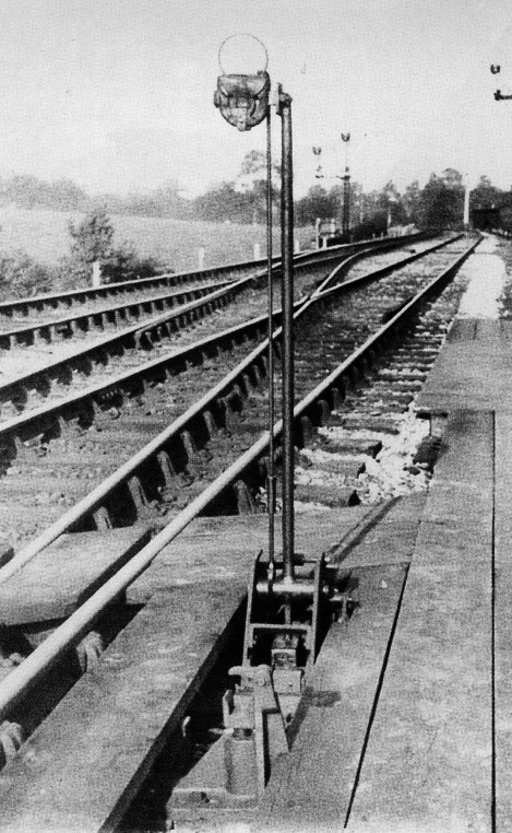 There was a normal pattern of pick-up post provided at Templecombe (No 2) Junction
near the south end of the signal-box for trains running from the Down Main onto the single-line towards Stalbridge.
However this could not be used by trains coming from the Up Main across the
south crossover (points 12) to access the single-line as the curvature of the points meant
that the post was too far away from the receiver on the locomotive. Accordingly a
different, and much slimmer, form of 'falling man' was provided as an separate
pick-up post for those trains, which normally lay completely flat down in the
cess at the side of the Down Main (click
here for image). There is photographic evidence that
originally the
'normal' post was sited near the north end of the signal-box; it is probable, but not proven, that it was relocated to the south end when the signal-box's
doorway and access steps were moved to that end (which had happened by 1914).
It is unclear whether the 'falling-man' deliverer was already in use at that
time, or what other arrangements may have existed originally for trains coming
from the Up Main to collect the tablet.
There was a normal pattern of pick-up post provided at Templecombe (No 2) Junction
near the south end of the signal-box for trains running from the Down Main onto the single-line towards Stalbridge.
However this could not be used by trains coming from the Up Main across the
south crossover (points 12) to access the single-line as the curvature of the points meant
that the post was too far away from the receiver on the locomotive. Accordingly a
different, and much slimmer, form of 'falling man' was provided as an separate
pick-up post for those trains, which normally lay completely flat down in the
cess at the side of the Down Main (click
here for image). There is photographic evidence that
originally the
'normal' post was sited near the north end of the signal-box; it is probable, but not proven, that it was relocated to the south end when the signal-box's
doorway and access steps were moved to that end (which had happened by 1914).
It is unclear whether the 'falling-man' deliverer was already in use at that
time, or what other arrangements may have existed originally for trains coming
from the Up Main to collect the tablet.
[Note: in an archive video of colour film take at Templecombe (No 2) Junction in BR days (click here) there is a short 10-second sequence at time-stamp 2:12-2:22 showing the signalman raising the 'falling man' deliverer and inserting a tablet pouch. The normal pattern pick-up post can be seen alongside it.]
There was one instance on the S&DJR where a Whitaker apparatus was used other than for a single-line tablet. In 1927 a pick-up post was installed at Binegar adjacent to the Down line for the purpose of delivering the Bank Engine staff for Masbury Summit. This was a normal pattern of 'deliverer' standard, with the exception that the pouch holder was a different design to cater for the specific type of pouch that held the bank engine staff. When the bank engine returned 'wrong line' from the summit to Binegar it would cross over to the Up line and the pouch would be given up by hand to the signalman. The Binegar standard survives in the collection of the Somerset & Dorset Railway Trust and can be seen here.
The 1960 BR(SR) Western Section Sectional Appendix included instructions (provided as 'Note A' to Table D1) about the use and maintenance of the Whitaker apparatus (click here for the full text). The Signal Engineer's Department was responsible for the maintenance of the lineside standards and they would check them with a gauge to ensure that they were located correctly in relation to the track. It is believed that the Locomotive Department was responsible for the exchangers fitted to the engines and they would 'gauge' them in a similar manner. The signalmen were responsible for 'gauging' the actual pouches in their signal-boxes and were instructed not to use any found to be defective. The Sectional Appendix instructions mandated that "...with the exception of ballast trains, trains where the engine stops near the signal box and engines running tender first, when the token must be exchanged by hand, the apparatus must always be used and the token exchanged automatically...". In the event that an engine had no (or defective) Whitaker apparatus, then signalmen would be informed by telephone of the need to exchange tablets by hand (using the 'large' pouches kept in the signal-boxes for such purposes), the relevant messages being prefixed by the code-word 'POUCH'.
[Note: by the time of the 1960 BR(SR) Western Section Sectional Appendix the line north of Henstridge was under the control of BR(WR) and it is believed that similar instructions were contained in the equivalent BR(WR) document. The 'Note A' instructions used the generic term 'token' rather than a specific reference to 'tablet'.]
© CJL Osment 2019-26
Acknowledgements to Mike Arlett, Peter Trenchard, Edward Dorricott, John Palmer and the late Peter Cattermole
for information, also to John Lacy from material from Signalling Record
Society archives.
Red lineman's board photograph courtesy Steph Gillett,
oval lineman's board photograph courtesy National Railway Museum,
Dutton plates photograph courtesy Edward Dorricott, No 3 plate photograph courtesy Barry Bax,
'approaching Shillingstone' photograph courtesy Adrian Vaughan, 'falling man'
receiver photograph courtesy the late David Milton, 'falling man'
deliverer photograph courtesy the late Peter Cattermole, Cole SB diagram
photograph courtesy GW
Railwayana Auctions, mystery Westinghouse FPL+detector photograph courtesy
Kevin Mitchell, fogman's hut photograph courtesy Ian Evans, Templecombe Junction
repeaters photograph courtesy Ian Matthews, Midford 'banner' repeaters
photograph courtesy Nick McCamley, other images WCRA collection.
References
|
© West Country Railway Archives 2019 Page last updated: 02 May 2026 |
URL:
E-Mail: |
||||||


