


 |
Somerset &
Dorset Joint Railway The Signals |
|
|||||
|
|||||||
This page provides general information about the different types of Signals which were used on the Somerset & Dorset Joint Railway (S&DJR). Specific details on individual S&DJR signals are contained within a separate RailWest Register of S&DJR Signals. The information in this page has been divided into four main sections:- (1) early 'disc-and-crossbar' and 'rotating disc' signals, (2) later semaphore signals, (3) ground signals, (4) miscellaneous indicators etc.
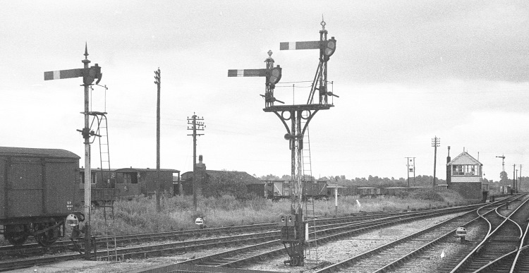
A variety of S&DJR signals at Highbridge station in 1965
Two different patterns of ground-signal, two different
types of signal post, and three different styles of finial !
| Disc-and-Crossbar and Rotating Disc Signals |
Information about the earliest forms of signals on the S&DJR (and its predecessor companies) is very scarce. It was suggested by the late Robin Atthill (in his book "The Somerset & Dorset Railway" [Ref 1]) that the Somerset Central Railway (SCR) used disc-and-crossbar (D&C) signals similar to those of the Bristol & Exeter Railway, whilst the Dorset Central Railway (DCR) used rotating disc signals similar to the 'Martin' type of the London & South Western Railway (L&SWR). Although that would seem to be a reasonable theory given the origins of the SCR and DCR lines, there is no known contemporary evidence for the use of the L&SWR 'Martin' style, and when this issue was discussed with Atthill he could not recall the source of his information. The Somerset & Dorset Railway (S&DR) Rule Book of 1864 contains illustrations of the D&C type only and there are subsequent references in official records to D&C signals at various ex-DCR locations being abolished or replaced by semaphores until as late as 1902, but no mention of any surviving 'Martin' signals. According to the late CR Clinker, the last D&C signals on the S&DJR were at Milldown Crossing (just north of Blandford) and were abolished on 8-August-1902 (S&DJR Signal Instruction No 158).
One possible theory is that the initial section of the DCR (from Wimborne to Blandford) did indeed use the L&SWR style of 'Martin' signal but that, when the DCR was extended subsequently to join the SCR near Cole and form the S&DR, it was decided to adopt the D&C type of signal already in use on the SCR as the common type across the S&DR. In that context therefore it is useful to note that, in an article about the early days of the S&DJR which appeared in the February 1905 edition [Ref 3] of the Railway Magazine (click here to see an extract from Page 127), it was stated that:-
"The signals were of the perforated disc and crossbar pattern on the Somerset portion of the line, as far as Templecombe, east of which they were for the most part similar to those used on the London and South Western Railway, consisting of a solid metal disc with a crescent-shaped portion cut out of the interior of the disc, which revolved on a pivot..."
The reference to the use of D&C signals extending as far east as Templecombe would imply that they had been used on not just the former SCR but also that part of the former DCR which included Cole and Wincanton stations. Equally the suggestion that the 'Martin' type signals were used 'for the most part' east of Templecombe would suggest that there were examples on the former DCR of a different type of signal, probably D&C but maybe an even earlier style. Given that the Railway Magazine article was published in 1905 and the last known example of D&C signals had been abolished in 1902, it is unclear as to the age and origin of the information quoted above. Was that article perhaps the source used subsequently by Atthill [Ref 1]? Some basic information about 'Martin' type signals can be found in Section 1 (images 1.11-1.15) of the 'Railway Signs and Signals of Great Britain' website here.
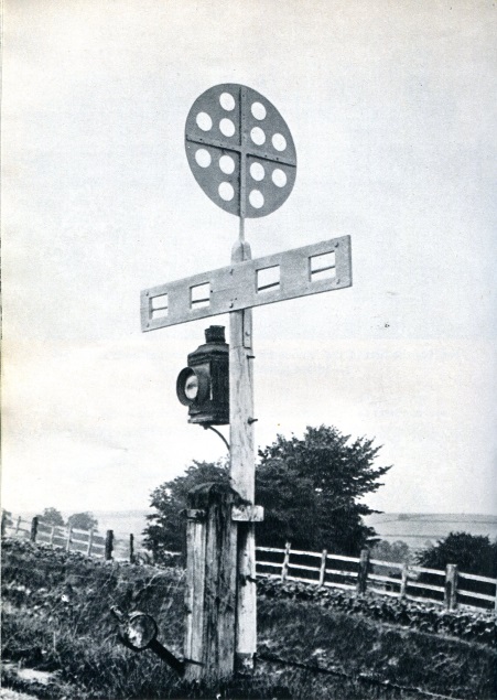 As its name implies, a D&C signal comprised a large disc mounted above, and at
right-angles to, a crossbar and fixed to a long vertical spindle attached to a
wooden post. The spindle could be rotated so that either the disc or the
crossbar faced an oncoming train; the former was the 'proceed' indication, the
latter meant 'stop'. Both disc and crossbar were pierced by several holes in
order to reduce their resistance to wind. The only known photographs of D&C signals on the S&DJR are of two signals at Spetisbury,
one of which is illustrated here (click picture for larger image). The S&DR Rule Book makes no mention of the colour of D&C signals. If
it is assumed that the SCR followed B&ER practice,
and the latter in turn copied the Great
Western Railway (GWR), then GWR practice might give some guidance. Most books
about the GWR are rather vague on the subject, but it would appear that both the disc
and the crossbar were red; apparantly Mr Brunel claimed that the distinction between
'stop' and 'proceed' came from the shape rather than the colour. (Note however that the lamp colours at night were red for
'stop' and white for 'proceed'; obviously 'shape' was of no use in the dark!)
Careful comparison of the various photographs from Spetisbury suggests that
both the disc and crossbar were painted the same colour on both sides,
and also that the colour extended down the top part of the post to about 6" below the bar.
As its name implies, a D&C signal comprised a large disc mounted above, and at
right-angles to, a crossbar and fixed to a long vertical spindle attached to a
wooden post. The spindle could be rotated so that either the disc or the
crossbar faced an oncoming train; the former was the 'proceed' indication, the
latter meant 'stop'. Both disc and crossbar were pierced by several holes in
order to reduce their resistance to wind. The only known photographs of D&C signals on the S&DJR are of two signals at Spetisbury,
one of which is illustrated here (click picture for larger image). The S&DR Rule Book makes no mention of the colour of D&C signals. If
it is assumed that the SCR followed B&ER practice,
and the latter in turn copied the Great
Western Railway (GWR), then GWR practice might give some guidance. Most books
about the GWR are rather vague on the subject, but it would appear that both the disc
and the crossbar were red; apparantly Mr Brunel claimed that the distinction between
'stop' and 'proceed' came from the shape rather than the colour. (Note however that the lamp colours at night were red for
'stop' and white for 'proceed'; obviously 'shape' was of no use in the dark!)
Careful comparison of the various photographs from Spetisbury suggests that
both the disc and crossbar were painted the same colour on both sides,
and also that the colour extended down the top part of the post to about 6" below the bar.
| Semaphore Signals |
|
||||||||||
The familiar semaphore signal probably first arrived on the S&DJR in large numbers with the opening of the Bath Extension in 1874 and the rest of this section deals with the subsequent period. Minute 27 of the S&DJR Officers Meeting on 1-October-1875 stated "...all disc-and-crossbar signals on the line to be superseded by semaphores as renewal becomes necessary...", but it is clear from various official records that some D&C signals lingered until 1901-02. After the formation of the 'Joint' line in late 1875 the L&SWR assumed responsibility for its signalling, but although in later years there was much evidence of the influence of both the L&SWR and the subsequent Southern Railway (SR), nevertheless the S&DJR still managed to display its individuality. Some suitable illustrations can be found in "A Pictorial Record of Southern Signals" by the late GA Pryer [Ref 2] and are referenced in this page as 'PRSS'.
Note: At the extremities of the S&DJR system, where it connected with the lines of other railway companies, there were a few signals on S&DJR lines which were controlled by a signal-box of another company. Such signals may have been provided by the other companies to their own designs and have been excluded from the scope of this page.
Three main materials were used for S&DJR semaphore signal posts:- wood, steel lattice and old rails. The Bath Extension probably was equipped throughout originally with wooden posts and it is likely that these were used for work elsewhere on the line in the 1870s and 1880s. Certainly wooden posts were still being used as late as 1892 in connection with the doubling of the line at Midford. However the metal lattice post appears to have come into use circa-1900 and this was identical to the L&SWR pattern (PRSS Fig 15). There were also two known examples of concrete posts (one at Glastonbury and the other at Evercreech Junction), both of them for signals which were first installed in December 1929; this seems too much of a coincidence not to assume that those concrete posts were the original posts at that time. Although the SR was a prolific user of concrete for some of its infrastructure (eg fence posts etc), concrete signal posts appear to have been relatively uncommon and it may well be that the two examples quoted were indeed the only ones on the S&DJR.
[Note: Bowring ([Ref 4] page 113) suggests the high cost and weight in transportation and erection as factors which made concrete posts unsuitable for signals.]
 Signal posts constructed from old rails were
a common sight on the SR in later years, but this method of construction was neither
invented by, nor exclusive to, the SR. It is unclear exactly when or why the
S&DJR started using rail-built posts, but they appear to have been in use by
about 1905 and there is some circumstantial evidence to suggest that they
were introduced in the 1890s. It is possible also that this type
of construction may have been superseded prior to the 1923 Grouping,
presumably by a return to lattice posts, as at least one S&DJR
rail-built post is known to have been replaced by a lattice post prior to that
date. In due course the SR introduced their own design of rail-built posts and their first use
appears to have been on the Wimbledon-Sutton line in mid-1929 (when they were described as
"a novel idea" - clearly the reporter had not visited the S&DJR!), so the SR pattern may have begun to appear on the S&DJR in
the early 1930s.
Signal posts constructed from old rails were
a common sight on the SR in later years, but this method of construction was neither
invented by, nor exclusive to, the SR. It is unclear exactly when or why the
S&DJR started using rail-built posts, but they appear to have been in use by
about 1905 and there is some circumstantial evidence to suggest that they
were introduced in the 1890s. It is possible also that this type
of construction may have been superseded prior to the 1923 Grouping,
presumably by a return to lattice posts, as at least one S&DJR
rail-built post is known to have been replaced by a lattice post prior to that
date. In due course the SR introduced their own design of rail-built posts and their first use
appears to have been on the Wimbledon-Sutton line in mid-1929 (when they were described as
"a novel idea" - clearly the reporter had not visited the S&DJR!), so the SR pattern may have begun to appear on the S&DJR in
the early 1930s.
The method of construction for rail-built posts varied between the two Companies. The S&DJR pattern normally consisted of two rails bolted tightly together (see picture - click for larger image), so that at a distance they appeared to be a single rail and sometimes are described erroneously as such in photograph captions, even though the heads of the bolts holding together the two rails can be seen. Although the two-rail method provides better strength, it appears that a few short examples did have only a single rail. The SR type had two rails held about 9 inches apart by spacers in an elongated 'H' pattern. S&DJR-pattern posts were erected with the rail web at right-angles to the track, while the SR type had the rail web parallel to the track.
Most S&DJR bracket signals had the 'dolls' standing up above the actual bracket, but there were also examples of 'gallows' signals where the dolls were suspended below the bracket (eg West Pennard and Wells). For rail-built bracket signals the S&DJR design appears to have been essentially a straight rail-built post with a frabricated bracket attached to it. It has been suggested that the dolls may have been only single rails - possibly because of their short length or the need to reduce weight on the bracket - but certainly one example is known to have had a two-rail doll. In the SR design the main post was often more substantial, with at least four rails, but the individual dolls were always lattice in order to reduce the weight. There was one known example (at Templecombe Junction) of a signal gantry which spanned the tracks and was supported on posts at both ends.
In 1960 two examples of British Railways (Western Region) tubular steel posts were erected at Midford and another example was installed at Masbury by mid-1961. In March 1966 a short BR(WR) tubular doll was fitted to an existing SR rail-built bracket signal at Highbridge as part of the alterations to retain the line to Bason Bridge for milk traffic (after the closure of the S&DJR to passenger traffic). It is possible that there may have been other BR(WR) tubular post installations which have not been identified as such because they escaped the photographic record (one potential example being the Down Distant at Wincanton, which was renewed in 1960).
It will be evident from the RailWest Register of S&DJR Signals that most signal posts were replaced at some stage during their lifetime, often by one of a different pattern. Many signals have escaped the photographic record altogether, either because they were abolished at an early date or because they were sited at locations rarely visited by photographers (eg the relatively remote locations of most Distant signals). It would appear from available information that by the early 1950s only three examples were known of signals still on wooden posts, of which two existed at Midford (the Down Starting and Down Advance Starting signals) until they were replaced by BR(WR) tubular posts in 1960. The third example was the Down Distant at Glastonbury, which remained as a wooden post (with an UQ arm) until the line closed in 1966 and therefore may have been the last surviving wooden signal post on the S&DJR (click here for photograph).
Note: The information given above may seem to imply a chronological progression in signal post style from wood through lattice and S&DJR rail-built to SR rail-built. While this is probably roughly true, the type of post used is not necessarily an accurate indicator for the age of any signal. For example, in the 1940s there were two separate instances when both lattice and SR rail-built posts are believed to have been installed at the same station on the same day! It was probably the case that, for economy purposes, the signal department simply re-used whatever material it might have available as much as possible, rather than always providing the 'latest type' of post. In addition, the actual distribution of the S&DJR style of rail-built posts across the whole of the S&DJR is something of a puzzle; although they were used in many places on the Bath Extension and the various Branches, only two examples (one at Shillingstone and the other at Corfe Mullen Junction) are known to have existed south of Templecombe Junction.
![]() Types. Most, if not all, of the wooden signal posts appeared to have been fitted
with a 'ball-and-spike' pattern of finial. A few examples could be found also on
lattice posts, but generally the latter used an open cruciform style that had
been adopted by the L&SWR (PRSS Fig 15). The
preserved example shown on the right here (not of S&DJR origin - click
photo for a larger image) is a good
example of the 'generic' L&SWR type, which was manufactured by a number of
different companies. While most were devoid of any inscription (as in this
example), some companies cast their name and location around the base and/or on
the 'arms', and quite a few appear to have been manufactured by Evans O'Donnell
of Chippenham.
Types. Most, if not all, of the wooden signal posts appeared to have been fitted
with a 'ball-and-spike' pattern of finial. A few examples could be found also on
lattice posts, but generally the latter used an open cruciform style that had
been adopted by the L&SWR (PRSS Fig 15). The
preserved example shown on the right here (not of S&DJR origin - click
photo for a larger image) is a good
example of the 'generic' L&SWR type, which was manufactured by a number of
different companies. While most were devoid of any inscription (as in this
example), some companies cast their name and location around the base and/or on
the 'arms', and quite a few appear to have been manufactured by Evans O'Donnell
of Chippenham.
![]() The S&DJR-pattern rail-post signals had a cruciform
version of the ball-and-spike finial, of which at least two
designs are known. It would appear that the earlier rail-post finials were cast, whereas the
later ones were fabricated, and it is probable that the latter process
led to variances in the design. The photograph on the left (click for a larger image)shows a fabricated S&DJR finial
now in the Radstock
Museum which come from a S&DJR-pattern rail-built post on the
Clandown Branch. There were differences also in the fixing
arrangements, as some surviving finials have a single bracket projecting from
the bottom for fixing to the rails, whilst others have a pair of brackets. It is
possible that most, if not all, of these finials were made at the S&DJR
works at Highbridge.
The S&DJR-pattern rail-post signals had a cruciform
version of the ball-and-spike finial, of which at least two
designs are known. It would appear that the earlier rail-post finials were cast, whereas the
later ones were fabricated, and it is probable that the latter process
led to variances in the design. The photograph on the left (click for a larger image)shows a fabricated S&DJR finial
now in the Radstock
Museum which come from a S&DJR-pattern rail-built post on the
Clandown Branch. There were differences also in the fixing
arrangements, as some surviving finials have a single bracket projecting from
the bottom for fixing to the rails, whilst others have a pair of brackets. It is
possible that most, if not all, of these finials were made at the S&DJR
works at Highbridge.
Although it might appear that, in general, the type of finial was dependant upon the nature of the post to which it was fitted, it would seem that the S&DJR was not averse to using whatever came to hand. For example at Highbridge there is photographic evidence that, in addition to the 'usual' patterns of finial, there were two examples of a Dutton 'spear-head' finial and also an 'open-ball' finial of a style more commonly seen on signals in Scotland! Two more Dutton 'spear-head' finials were fitted to a bracket signal at West Pennard. (One may speculate that the Dutton finials could have been relics from the original Dutton installation for the Bridgwater Branch, but alternatively they may have originated from elsewhere on the L&SWR.) It was not unknown also for two dolls on a bracket signal to have different styles of finial.
Examples of Evans O'Donnell (EoD) 'arrow-head' finials, similar to those used initially on the Lynton & Barnstaple Railway (click here to see a L&BR example), were photographed at Cole on the Down Starting signal circa-1949 and the Up Home signal in 1959, although by that time the former had been replaced by an L&SWR-style 'lattice post' example. It is believed that another EoD 'arrow head' existed on the Down Distant at Bason Bridge, but the photographic evidence is inconclusive and it is possible that actually it had a Dutton 'spear-head' finial.
The SR pattern of rail-built posts had a simple low pyramid-shaped finial, while the few BR(WR) tubular posts used the standard BR(WR) form of 'open' ball-and-spike finial. Any concrete posts appear to have had no finial at all, but were merely manufactured with a pyramid-shaped top.
Painting. The painting scheme for S&DJR finials has been a matter of much debate and perhaps is best described as 'unclear'! Research into anything pre-1950 has to rely mainly on black-and-white photographs, where it is difficult often to tell whether an area of dark colour is black or red paint or just the result of years of dirt and smoke accumulating on white paint. In theory both the L&SWR and SR painting schemes specified that finials should be painted white all over, but there is some evidence that elsewhere on the L&SWR the 'ball' or 'swell' part of some finials was painted red, whilst in later SR days there were many examples where the ball/swell or even the whole finial was a dark colour. Much of the difference perhaps can be put down to 'local variations' in both 'custom and practice' and the interpretation of the official painting schedules, such as whether a finial was part of the signal post (to be painted white) or part of the fittings (dark grey).
It is evident from colour photographs that post-1950 on the 'Somerset' part of the S&DJR it was common for the finials to be painted generally white, but with red (for stop signals) or yellow (for distant signals) on the ball/swell part. (In the case of SR rail-built posts, the whole 'cap' was painted in the relevant colour.) As this was standard practice on the Western Region, it had been thought that this use of red (or yellow) was simply a result of BR(WR) gaining control of the northern part of the railway during the 1950s, especially as the 'Dorset' part continued to show Southern Region influence with mostly all-white finials. However it may well be the case that BR(WR) in fact was simply perpetuating an existing S&DJR colour scheme, albeit perhaps with a greater degree of consistency across the railway.
It is evident also from the photographic record that many S&DJR signal posts had their finials changed over the years. In some cases this may have been done as part of the process of replacing the entire post, whereas others may have resulted merely from the replacement of a damaged finial. It is probable that any such replacements were done using any spare finial that was available, regardless of its type, as long as it would fit the post, without any attempt to maintain a strict correlation with the 'traditional' type of finial for its destination post. In later years at least therefore such a practice may have been the reason behind the eclectic mix of finials to be found across the S&DJR. In some cases a signal post simply 'lost' its finial for some reasons (eg blown off in a storm or fell off because of rust etc) and sometimes no one ever bothered to replace it.
Signal arms consisted of a 'blade' attached to a metal spectacle plate casting, which incorporated a socket for the arm pivot. Signal blades were made from wood originally and the overall arm design was a lower-quadrant (LQ) pattern similar to that used by the L&SWR. The spectacle castings appear to have been obtained from a number of suppliers including Dutton, Saxby & Farmer (S&F) and the Railway Signal Company (RSC). Upper-quadrant (UQ) arms began to appear in SR days and these had metal blades, usually with distinctive horizontal corrugations which were provided to give greater strength to the sheet metal arm. (It is possible that some LQ arms were also fitted with metal blades.) The first use of UQ arms on the Southern Railway itself was at Liphook on 25-March-1928 (SR Signal Instruction 11 of 1928), where all seven main running signals were changed to UQ "as an experiment" (see Bowring [Ref 4] page 109). It is not known exactly when or where the S&DJR started to use UQ arms, as Signal Instructions for new or replacement signals rarely made any reference to any change from LQ to UQ, but evidence would suggest that LQ arms were still being fitted on new signals as late as 1929 (eg at West Pennard) and possibly even 1931 (eg Masbury).
UQ arms were used mainly on the SR-type rail-built posts and on lattice posts and a few examples were known on the S&DJR-type rail-built posts. Only two examples are known of UQ arms on a wooden post (one at Midford and the other at Glastonbury) and both of those are believed to have been replacement arms on existing posts. (The Midford example was the Down Starting signal (No 3), which was damaged in the 1936 'runaway train' accident; it is a possible theory therefore that the UQ arm was fitted when that signal was repaired, but this can not be proven.) LQ arms of the BR(WR) style were fitted to the few BR(WR) tubular post signals that were installed in the 1960s.
Note: Although it is apparent that the SR type of rail-built signal post was not introduced until after the adoption of UQ arms, there were many examples elsewhere on the former Southern Railway where LQ arms were fitted to SR rail-built posts. It is possible that there was a transition period during which the SR was using up existing stocks of LQ fittings on its new type of post and/or a desire not to have a 'mix' of quadrants at any particular location. On the S&DJR there were certainly a few known examples where LQ arms were fitted on SR rail-built posts, but most of their posts of that type had UQ arms.
Stop arms were painted red with a vertical white stripe on the front, white with a vertical black stripe on the rear. Spectacle plates originally displayed red and white aspects, but the white was replaced by green by about 1895. During the SR period a few examples appeared of stop arms which had a large black ring fixed to their front face. Although this style had been used extensively by the S&DJR for subsidiary arms, the use for main running signals was limited and confined to signals controlling movements to or from goods lines. All known S&DJR examples are listed in RailWest in a separate Register of Ringed Arms.
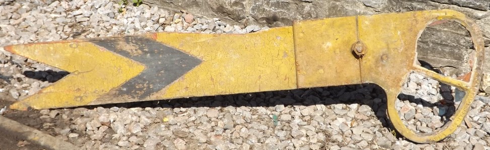
Distant arms. There is no specific information is available on the early style of distant arms but probably this followed the general British development. Originally identical to stop arms, from 1872 distant arms were distinguished by a V-notch cut in the end and later the vertical white stripe on the front was replaced by a white chevron; the rear appears to have retained a black stripe even when the front changed to a chevron. From about 1925/7 onwards all distant arms would have been re-painted in the new standard of yellow with a black chevron on the front and white with a black chevron on the rear. Spectacle plates originally displayed red and white aspects, but the white was replaced by green by about 1895 and eventually the red aspect was superseded by yellow at the same time that the arms were repainted yellow.
Note: although not strictly of relevance to the S&DJR, it may be useful to mention here the Coligny-Welch indicator. This device, which was fitted to distant signals by some railway companies, showed an illuminated white chevron to the right of the main signal aspect as a mimic for the notched end of the distant arm. The L&SWR was fitting these indicators to its distant signals in the Wimborne and Poole areas in the early 1900s, yet curiously there is no evidence that they were ever used by the S&DJR. Only two distant signals actually on S&DJR lines are known to have been fitted, one of which was the Down Branch Distant for Broadstone (which of course was a L&SWR signal-box anyway), but the fitting date is unknown. The other example was fitted on 31-May-1910 (S&DJR Signal Instruction 215) to the Up Branch Distant for the L&SWR signal-box at Wimborne Junction, which was an arm below the Down Home of the S&DJR Wimborne Loop box. Coligny-Welch indicators became superfluous and were removed when the red aspect on distant arms was changed to yellow.
| Examples of surviving ex-S&DJR signal arms | ||
 |
 |
|
| Distant arm from Moorewood (with S&F casting) | Stop arm from Radstock (with Dutton casting) | |
| Click thumbnails for larger images | ||
Ringed Arms. S&DJR 'Calling On' and 'Shunt Ahead' signals originally took the form of a full-size arm painted red with a white spot, surmounted by a black ring, the back of the arm being painted white with a black spot (PRSS Plate 81). The S&DJR seems to have described all such signals simply as 'Shunt By' signals (eg 'Shunt By Down Home' etc), regardless of their function. Sadly there are no known records to advise whether the 'on' aspect of these signals showed a red light, or a white light as was the practice with the later replacement striped arms (described below). Most of the surviving S&DJR Signal Instructions (SI) which refer to ringed arms relate either to their abolition or replacement by one of the new 'striped' versions; the only known Instruction for a new subsidiary ringed arm is SI 251 for Stalbridge No 12 in 1915, but this make no mention of the aspects. Although the various SIs for the later replacements are specific in stating that the new signals have white lights for 'on', it is not possible to know whether they represented the continuation of an existing practice or a change in practice from a previous use of red aspects. All known examples of S&DJR subsidiary signals are listed in RailWest in a separate Register of Ringed Arms, which also includes details of the various LQ and UQ replacement striped arms. At locations where a subsidiary arm was converted to UQ the alteration appears to have coincided with the conversion of the main arm from LQ to UQ.
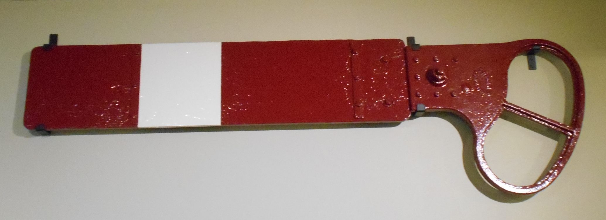
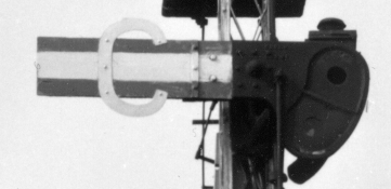
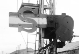
Striped Arms. In the late 1920s the Railway Clearing House standardised on the use of a small arm for subsidiary signals, painted white with horizontal red bands along the top and bottom edges, and displaying a white light for the 'on' aspect. [Use of white for 'on' meant that a driver could pass a main arm showing green for 'off' without having a conflicting red from the subsidiary arm.] The SR put a large red 'C' or 'S' (for 'Calling On' or 'Shunt Ahead' respectively) on the face of such arms, with the reverse of the arm being painted white with a broad horizontal central black band; most, if not all, of those arms were shorter than their 'ringed' predecessors. The earliest known examples of such arms on the S&DJR were LQ examples installed at Glastonbury in December 1929 (SI 300). At some unknown date UQ versions of these arms were introduced, although only 'S' examples are known on the S&DJR. All the Signal Instructions for these 'striped' arms stated that a white light was displayed for the 'on' aspect and that included the later versions with indicators (described below).
|
|
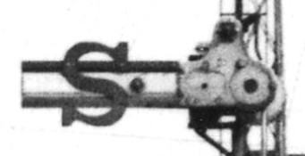 |
The images above show some S&DJR examples of SR-style 'striped' subsidiary arms with superimposed letters. On the left is a LQ 'Calling On' arm (Glastonbury No 28), in the middle is a LQ 'Shunt Ahead' arm (Glastonbury No 3PUSH), and on the right an UQ 'Shunt Ahead' arm (Highbridge 'C' No 17PULL). It will be noted that all the arms had spectacle plates with 'reduced' aspects (see below), but of different sizes, and one of the LQ examples also had an Annett's Shield. Although SI 300 for the replacement arm for Glastonbury No 28 in 1929 stated that it had a red 'C', it would appear from the photograph that in the BR period it was white - another example of the many variations in S&DJR signalling practice over the years.
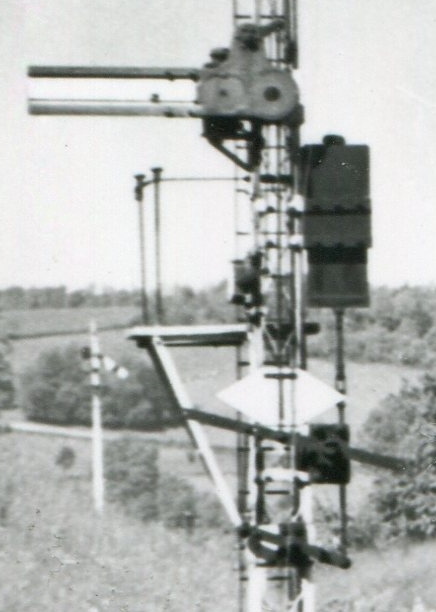 Arms with Indicators. In 1938 the Southern Railway provided a
new signal-box at Templecombe (at the 'Upper' station) and as part of that
work a subsidiary 'Warning' arm was provided on the post of the Up Branch
Advanced Starting signal (on the connecting spur to the S&DJR) which also
carried the 'From SR Inner Distant' arm for
Templecombe No 2 Junction box. This new subsidary signal was an UQ
striped arm, but instead of a letter superimposed on the arm there was an
associated indicator box fixed on the right-hand side of the signal post;
when the arm was raised to the 'off' position a cover was moved clear of the
indicator box to reveal a black screen with an internally-illuminated white
'W'. Although not actually a signal controlled from a
S&DJR signal-box, it was the first known signal of that type anywhere on the S&DJR. Despite this,
the older style of striped UQ arm with superimposed letter was used again in
1941 when Highbridge 'C' No 17PULL was renewed in 1941. Further examples of the 'indicator' style of
arm then appeared with renewal work in the BR period, with examples at
Midford in 1948 ('W'
indication), Templecombe No 2 Junction in 1956 ('C'
indication), Stalbridge in 1959 ('S' indication) and
Sturminster Newton at an unknown date prior to 1959 ('S'
indication).
Arms with Indicators. In 1938 the Southern Railway provided a
new signal-box at Templecombe (at the 'Upper' station) and as part of that
work a subsidiary 'Warning' arm was provided on the post of the Up Branch
Advanced Starting signal (on the connecting spur to the S&DJR) which also
carried the 'From SR Inner Distant' arm for
Templecombe No 2 Junction box. This new subsidary signal was an UQ
striped arm, but instead of a letter superimposed on the arm there was an
associated indicator box fixed on the right-hand side of the signal post;
when the arm was raised to the 'off' position a cover was moved clear of the
indicator box to reveal a black screen with an internally-illuminated white
'W'. Although not actually a signal controlled from a
S&DJR signal-box, it was the first known signal of that type anywhere on the S&DJR. Despite this,
the older style of striped UQ arm with superimposed letter was used again in
1941 when Highbridge 'C' No 17PULL was renewed in 1941. Further examples of the 'indicator' style of
arm then appeared with renewal work in the BR period, with examples at
Midford in 1948 ('W'
indication), Templecombe No 2 Junction in 1956 ('C'
indication), Stalbridge in 1959 ('S' indication) and
Sturminster Newton at an unknown date prior to 1959 ('S'
indication).
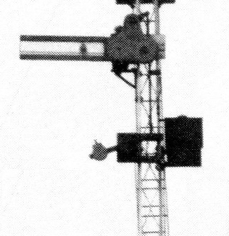 Photographic evidence suggests that the indicator provided at
Midford (shown
in the upper picture on the right) was similar to the one provided at Templecombe (Upper)
in 1938, whereas the lower picture on the right shows a smaller version provided at
Templecombe Junction in 1956. The indicator at
Sturminster Newton was similar to
the 1956 type, whereas the later example at Stalbridge appears (from a
very poor cine-film image) to have been similar to the older Midford type. Comparison
with indicators installed elsewhere on BR (Southern Region) suggests that, in
the smaller type shown in the lower image (Templecome Junction), the cover was hinged at the
top and lifted outwards and upwards in order to reveal the indication. The
method of operation for the larger type shown in the upper image (Midford) is
unclear, but it is believed that the cover slid vertically upwards.
Photographic evidence suggests that the indicator provided at
Midford (shown
in the upper picture on the right) was similar to the one provided at Templecombe (Upper)
in 1938, whereas the lower picture on the right shows a smaller version provided at
Templecombe Junction in 1956. The indicator at
Sturminster Newton was similar to
the 1956 type, whereas the later example at Stalbridge appears (from a
very poor cine-film image) to have been similar to the older Midford type. Comparison
with indicators installed elsewhere on BR (Southern Region) suggests that, in
the smaller type shown in the lower image (Templecome Junction), the cover was hinged at the
top and lifted outwards and upwards in order to reveal the indication. The
method of operation for the larger type shown in the upper image (Midford) is
unclear, but it is believed that the cover slid vertically upwards.
Reduced Aspects. There were several instances on the S&DJR where the two spectacle plate aspects were largely 'blanked out', with just a small hole in the centre for the signal lamp to shine through; with one known exception (see below), this practice appears to have been confined to subsidiary arms, but it could be found on both LQ and UQ arms. (Note: it is not known if there was an official term for this arrangement, which will described in RailWest as a 'reduced' aspect.) There were probably two main reasons for the use of such 'reduced' aspects. Firstly, it might be confusing at night for the driver of an approaching train to see a full-size white light from a subsidiary arm in its 'on' position, but also a green light from an 'off' main arm just above it. Secondly, a subsidiary arm could not be cleared unless the main arm was 'on', and should only be passed at slow speed, so an approaching driver would see the red light from a main arm in the 'on' position and hence slow down long before the subsidiary arm was cleared and he then became aware of the much smaller green 'off' light from an 'off' subsidiary arm. A 'reduced' aspect was fitted also to the ringed-arm signal No 37 at the exit from the Lower Yard at Templecombe Junction, probably because this controlled a 'wrong-road' move and therefore may have been regarded as a 'shunt' rather than a 'main' arm.
Annett's Shields. On LQ arms the pivot was fixed on the centre-line of the post, with the result that both aspects were almost entirely to the right of the post. When the arm was horizontal in the 'on' position, there was a risk in some locations that stray light from the surrounding area (eg house or street lights) might be visible through the 'green' aspect and thereby give a false 'off' indication to the driver of an approaching train. In such cases it was common practice on the L&SWR, and hence also the S&DJR, for the signal to be fitted with an Annett's Shield; this was a semi-circular plate (usually painted grey or black) fixed by a bracket to the signal post to project up in front of, and obscure, the 'green' aspect when the arm was in the 'on' position. On UQ arms the pivot was to the left of the post, so the whole of the 'green' aspect was in front of the post and hence the problem was less severe; however lattice or SR-type rail-built posts were relatively 'open' structures, so it would appear that a rectangular plate was fixed to the front of the post immediately behind the arm.
Weight Levers. Each signal arm would be accompanied normally by a 'weight lever'. Sometimes this is called a 'balance lever' or 'balance weight', but in fact it has nothing to do with balancing anything, its purpose being to pull back any slack in the signal operating wire when the relevant lever at the controlling signal-box or ground-frame was replaced to its normal position. On L&SWR/SR/S&DJR signals the weight lever was placed usually on the post (or doll on a bracket) just a short distance below the arm, although there were variations to be found eg on a 'gallows' bracket with under-slung dolls the weight lever might be above the arm. Where there were two (or more) arms on a signal post/doll (eg a main arm + subsidiary arm, or a stop arm + lower distant arm), then the weight levers might be located separately or combined on a single pivot. Additional weight levers might be provided also where a signal was 'slotted', ie controlled by two different signal-boxes and/or ground-frames.
A weight lever usually was a straight metal bar which was pivoted off-centre, with the weight fixed near the end of the longer section and the operating wire from the signal-box/ground-frame attached to the end of the short section. For LQ arms there was a rigid metal 'down rod' (sometimes in two sections connected by a bottle-screw adjuster) which connected the long end of the weight lever to the spectacle plate casting on the signal arm just to the right of the arm pivot, so that when the operating wire was pulled the short end of the weight lever moved downwards, the longer end moved upwards, and the down-rod pushed the spectacle plate upwards, so that the arm itself lowered to the 'off' position. (If the down-rod broke while the signal was 'off' the weight of the spectacle plate alone was sufficient to raise the arm back to the horizontal 'on' position.) For UQ arms the down-rod connected the short end of the weight lever to a crank arm projecting from the right-hand side of the arm pivot, so that when the operating wire was pulled the short end of the weight lever moved downwards and so pulled downwards on the arm pivot lever, which raised the arm itself to the 'off position. (If the down-rod between the weight lever and the arm crank were to break while the signal was 'off' then the arm would fall back to the horizontal 'on' position simply by gravity.)
Although a weight lever was usually just a straight metal bar with a single circular-ish weight bolted onto it near the end of the longer portion, the size and/or number of weights could vary depending on the amount of slack in the signal operating wire and/or whether it was a 'stiff' or 'easy' pull. In some cases where there was a space restriction for some reason, the weight(s) might be on a separate bar hung vertically below the main bar by a hinged joint rather than projecting out from the post. It is possible also that in some cases the weight-lever took the form of a T-crank at the foot of the post, the wire from the lever-frame being attached to the bottom of the 'T', but such a variant is not easy to identify in most photographs. In the case of UQ arms only, if the signal was very close to the controlling signal-box/ground-frame and so the operating wire was quite short with virtually no slack, then a weight lever might not be provided anyway, the operating wire being connected directly to the arm pivot crank; although instances of this practice are known elsewhere, no S&DJR examples have been identified conclusively yet.
Note: the photographic record of S&DJR signals is incomplete and lacking in detail in many respects, so the foregoing comments are intended simply as an outline overview of the various known and possible variations in the style and installation of weight levers.
|
For 'wrong direction' movements over running lines a special 'wrong-road' signal was used which had a full-size arm in the shape of an elongated 'X', often referred to as a 'bow-tie' arm (PRSS Plate 83). This pattern of arm was a feature of installations by the signalling contractors Stevens & Sons and was not unique to the S&DJR, but sadly it is often described incorrectly as such in many publications. Although the 'wrong road' signal is perhaps the most well-known feature of S&DJR signalling, only five examples are known to have existed on the line. More details about these signals can be found in a separate RailWest page. |
 |
With four known exceptions, all the semaphore signals on the S&DJR were worked mechanically in the traditional manner, by means of wire runs from a mechanical lever-frame in the controlling signal-box or ground-frame. The first exception existed at Templecombe No 2 Junction signal-box, which gained a motor-worked Down Distant in 1933 after it took over the work of the former Templecombe No 3 Junction signal-box. Two further exceptions arrived in 1958, when alterations at the neighbouring Lamyatt and Bruton Road ground-frames (two level-crossings between Evercreech Junction and Cole) provided motor-worked Up and Down Distants that were controlled by both ground-frames. Finally in 1960 the Down Distant at Wincanton was converted to motor working when the existing signal was replaced by a new one much further away from the signal-box.
 There were also two examples of electrically-worked 'banner repeaters' on the
S&DJR in later years. One example was at Evercreech Junction North, just north of
bridge 107, and it was
installed on 4-January-1942 to repeat the North signal-box's Down Main Home signal;
a 1952 photograph shows a typical example of the Sykes pattern used by the SR
and installed on top of a SR-type rail-built post. The other example was on
the goods line between the Highbridge East 'B' and East 'A' signal-boxes in BR days, to repeat a pair of shunt signals at Highbridge East
'A' box, but the
exact date of installation is not known. This was also installed on a SR-type
rail-built post, but it was a smaller version than the type of repeater normally used with
main running signals (click picture for
larger image). In the absence of any information
to the contrary, it is assumed that banner 'arms' were painted black
against an opaque white background.
There were also two examples of electrically-worked 'banner repeaters' on the
S&DJR in later years. One example was at Evercreech Junction North, just north of
bridge 107, and it was
installed on 4-January-1942 to repeat the North signal-box's Down Main Home signal;
a 1952 photograph shows a typical example of the Sykes pattern used by the SR
and installed on top of a SR-type rail-built post. The other example was on
the goods line between the Highbridge East 'B' and East 'A' signal-boxes in BR days, to repeat a pair of shunt signals at Highbridge East
'A' box, but the
exact date of installation is not known. This was also installed on a SR-type
rail-built post, but it was a smaller version than the type of repeater normally used with
main running signals (click picture for
larger image). In the absence of any information
to the contrary, it is assumed that banner 'arms' were painted black
against an opaque white background.
There were never any colour-light signals on the S&DJR, but see the comments below about 'marker lights'.
| Ground Signals |
|
|||||||||
The terms 'ground signal' or 'ground shunt signal' were commonly applied to small signals used primarily for shunting purposes. As their name implies, most 'ground signals' were indeed located on the ground, but examples could be found which were elevated for sighting purposes on a short post, or part of the way up the same post as a main running signal, or even up on the platform of a bracket signal (see more about elevated ground signals below). The alternative terms 'ground disc' or 'disc signal' was used sometimes, even for ground signals which were not actually of a 'disc' form. Somewhat confusingly the term 'shunt signal' might be used also for other forms of signals (eg subsidiary arms) which were not regarded as ground signals.
 Point Indicators. The earliest form of ground signal was probably the 'point indicator' (sometimes
called 'point disc'). This was located next to a point and connected
directly to it, so that the 'signal' was operated by the actual movement of
the point itself from normal to reverse or vice-versa. It is known that point indicators did exist at
various locations on the S&DJR, as they are marked on signal diagrams for
places such as Ashcott, Burnham, Cole, Polsham, Shapwick, Shillingstone
and Wells, but most known examples appear to
have been abolished by 1948 or shortly thereafter. Consequently the style of
S&DJR point indicators is unclear, although photographic evidence from Wells circa-1900,
Burnham circa-1905, Cole circa-1950 and Polsham
in 1950 suggests that a version of the Stevens 'flap' signal (see below)
was used for this purpose, as can be seen from the picture on the right (click for larger
image) of an example at Burnham.
Some of the late survivors appear to have escaped the photographic record almost entirely,
other than the examples at Cole and Polsham. The flaw with point indicators was that they were not an 'independent' signal
which could be operated by the signalman by means of a separate lever; they only indicated the position of the point and
not whether it was safe to shunt past it or not.
Point Indicators. The earliest form of ground signal was probably the 'point indicator' (sometimes
called 'point disc'). This was located next to a point and connected
directly to it, so that the 'signal' was operated by the actual movement of
the point itself from normal to reverse or vice-versa. It is known that point indicators did exist at
various locations on the S&DJR, as they are marked on signal diagrams for
places such as Ashcott, Burnham, Cole, Polsham, Shapwick, Shillingstone
and Wells, but most known examples appear to
have been abolished by 1948 or shortly thereafter. Consequently the style of
S&DJR point indicators is unclear, although photographic evidence from Wells circa-1900,
Burnham circa-1905, Cole circa-1950 and Polsham
in 1950 suggests that a version of the Stevens 'flap' signal (see below)
was used for this purpose, as can be seen from the picture on the right (click for larger
image) of an example at Burnham.
Some of the late survivors appear to have escaped the photographic record almost entirely,
other than the examples at Cole and Polsham. The flaw with point indicators was that they were not an 'independent' signal
which could be operated by the signalman by means of a separate lever; they only indicated the position of the point and
not whether it was safe to shunt past it or not.
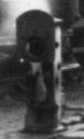
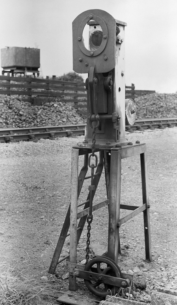
 'Flap'
Ground Signals. The
first known type of S&DJR 'independent' ground-signal was a Stevens & Sons design
known variously as a 'flap', 'drop-flap' or 'pillar' signal (PRSS Plate 79), which was widely used by the
L&SWR. In the 'on' position these signals displayed a large red-painted 'flap', in
the centre of which was a circular or oval aperture holding a red glass
illuminated by a lamp contained with the main 'pillar' of the signal. In the 'off' position
the flap dropped forward to reveal simply the white(ish) light. At some stage
the signal design was modified to provide a small two-aspect (red+green)
spectacle plate, fixed on the pillar in front of the light but behind
the flap, which moved from
'red' to green' as the flap was lowered. (It has been suggested that this
modification occurred because the red glass was susceptable to damage and a
cracked glass might fall out, thereby causing the white light to give a false
'off' indication while the signal was still in the 'on' position.) After this change it would appear that
the red glass in the flap was omitted, presumably because then it was considered
superfluous. See
here for an
illustration of such a signal in its 'on' and 'off' positions.
'Flap'
Ground Signals. The
first known type of S&DJR 'independent' ground-signal was a Stevens & Sons design
known variously as a 'flap', 'drop-flap' or 'pillar' signal (PRSS Plate 79), which was widely used by the
L&SWR. In the 'on' position these signals displayed a large red-painted 'flap', in
the centre of which was a circular or oval aperture holding a red glass
illuminated by a lamp contained with the main 'pillar' of the signal. In the 'off' position
the flap dropped forward to reveal simply the white(ish) light. At some stage
the signal design was modified to provide a small two-aspect (red+green)
spectacle plate, fixed on the pillar in front of the light but behind
the flap, which moved from
'red' to green' as the flap was lowered. (It has been suggested that this
modification occurred because the red glass was susceptable to damage and a
cracked glass might fall out, thereby causing the white light to give a false
'off' indication while the signal was still in the 'on' position.) After this change it would appear that
the red glass in the flap was omitted, presumably because then it was considered
superfluous. See
here for an
illustration of such a signal in its 'on' and 'off' positions.
 Although most of the Stevens 'flap' signals on the S&DJR were replaced by other types in
later years, a number did survive into BR days; for example there were two at
Evercreech Junction South
circa-1948 and in September 1952 there was still at least one at
Edington Junction and two at Bridgwater North.
Remarkably three survived in use at Highbridge until the
line closed to passenger traffic in March 1966 and two of those can be seen
in the picture on the right (click for larger image); the right-hand
signal survives in private hands and is dated 1892 on the back. Another survivor from Highbridge is
owned now by the Somerset & Dorset Railway Trust
and can be seen here;
this signal is unusual in that it has two weight levers and 'slotting'
gear, as it was controlled by both Highbridge East 'C' signal-box (the ex-S&DJR
'Highbridge Loco' box) and Highbridge Crossing signal-box (the ex-GWR
'Highbridge West' box). There may perhaps have been other S&DJR 'flap' signals which
survived beyond 1948, but were then replaced by a different pattern prior to
1966 and have escaped the photographic record; any further information on such
'survivors' would be welcomed.
Although most of the Stevens 'flap' signals on the S&DJR were replaced by other types in
later years, a number did survive into BR days; for example there were two at
Evercreech Junction South
circa-1948 and in September 1952 there was still at least one at
Edington Junction and two at Bridgwater North.
Remarkably three survived in use at Highbridge until the
line closed to passenger traffic in March 1966 and two of those can be seen
in the picture on the right (click for larger image); the right-hand
signal survives in private hands and is dated 1892 on the back. Another survivor from Highbridge is
owned now by the Somerset & Dorset Railway Trust
and can be seen here;
this signal is unusual in that it has two weight levers and 'slotting'
gear, as it was controlled by both Highbridge East 'C' signal-box (the ex-S&DJR
'Highbridge Loco' box) and Highbridge Crossing signal-box (the ex-GWR
'Highbridge West' box). There may perhaps have been other S&DJR 'flap' signals which
survived beyond 1948, but were then replaced by a different pattern prior to
1966 and have escaped the photographic record; any further information on such
'survivors' would be welcomed.
[Note: Stevens & Sons supplied 'flap' signals to a number of railway companies with variations from the basic design. It is important therefore not to assume that any 'flap' signal seen in a photograph or a museum collection etc will be identical to those used on the S&DJR. For example, the Somerset & Dorset Railway Heritage Trust have an example at Midsomer Norton South which came from a Scottish railway; it has a smaller circular hole in the face-plate (rather than the larger oval version seen in most S&DJR examples) which is complete with red glass as it does not have the 2-aspect spectacle plate modification.]
 'Miniature
Arm' Ground Signals. In due course the S&DJR started to use the 'miniature semaphore
arm' type of ground signal for any new or replacement work, but is unclear what
equipment was used initially or when it was introduced. There is
photographic evidence that the L&SWR had some examples elsewhere of Stevens ground
signals with miniature arms fitted onto the pillar instead of
the flap, but it is not known if any of those were used on the S&DJR.
(Note: the picture on the right here (click for larger
image) shows an L&SWR example purely
for illustrative purposes as an example of the style of such signals; the white
'pointing hand' on the face of the signal arm indicates the line to which the
signal applies.) There are references
in S&DJR Signal Instructions to the use of a 'ground
disc of the new pattern' at Templecombe No 3 Junction in 1907 and a 'new
semaphore ground signal' at Midsomer Norton
in 1910, but no photographic evidence is known for those items and so the style
of those ground signals is unknown. It is
possible that in fact those signals were of the later Westinghouse pattern
(see below), which is known to have been used elsewhere on the L&SWR by late 1909.
'Miniature
Arm' Ground Signals. In due course the S&DJR started to use the 'miniature semaphore
arm' type of ground signal for any new or replacement work, but is unclear what
equipment was used initially or when it was introduced. There is
photographic evidence that the L&SWR had some examples elsewhere of Stevens ground
signals with miniature arms fitted onto the pillar instead of
the flap, but it is not known if any of those were used on the S&DJR.
(Note: the picture on the right here (click for larger
image) shows an L&SWR example purely
for illustrative purposes as an example of the style of such signals; the white
'pointing hand' on the face of the signal arm indicates the line to which the
signal applies.) There are references
in S&DJR Signal Instructions to the use of a 'ground
disc of the new pattern' at Templecombe No 3 Junction in 1907 and a 'new
semaphore ground signal' at Midsomer Norton
in 1910, but no photographic evidence is known for those items and so the style
of those ground signals is unknown. It is
possible that in fact those signals were of the later Westinghouse pattern
(see below), which is known to have been used elsewhere on the L&SWR by late 1909.
 It is clear that by
early SR days the S&DJR were using 'miniature
semaphore' ground signals of the Westinghouse pattern, as shown on the left
here (click picture for larger image). While some of these
had red arms (illustrated), there were also a few examples with yellow arms (PRSS
Plate 87) installed specifically in locations where 'yellow ground
signals' were required. The earliest known use of a yellow arm version
on the S&DJR was at Masbury in 1928
in conjunction with a new siding. There were at least two, possibly three, with
red arms at West Pennard in BR days, with circumstantial
evidence that at least one (possibly two) of those was installed in 1929 as part of the
same layout alterations which also saw the provision of two yellow arms.
It is clear that by
early SR days the S&DJR were using 'miniature
semaphore' ground signals of the Westinghouse pattern, as shown on the left
here (click picture for larger image). While some of these
had red arms (illustrated), there were also a few examples with yellow arms (PRSS
Plate 87) installed specifically in locations where 'yellow ground
signals' were required. The earliest known use of a yellow arm version
on the S&DJR was at Masbury in 1928
in conjunction with a new siding. There were at least two, possibly three, with
red arms at West Pennard in BR days, with circumstantial
evidence that at least one (possibly two) of those was installed in 1929 as part of the
same layout alterations which also saw the provision of two yellow arms.
Two 'miniature semaphore' ground signals of the Westinghouse pattern with red arms (signals 13PULL and 13PUSH) existed at Evercreech Junction North for many years, the former being 'elevated' a couple of feet above ground level on a short post whilst the later was 'elevated' on a taller post. The precise history of those two signals is unclear, as 13PULL was provided originally as a new signal 13 in 1911, becoming 13PULL when a new 13PUSH was added in 1919; the original style of those two signals is unknown. 13PUSH was replaced as an 'elevated' ground signal in 1929 and 13PULL was relocated in 1940; the latter appears to have remained as a 'miniature semaphore' until the line closed in 1966, but photographic coverage of 13PUSH is inconclusive.
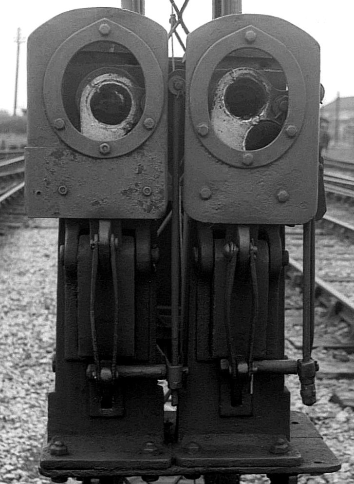
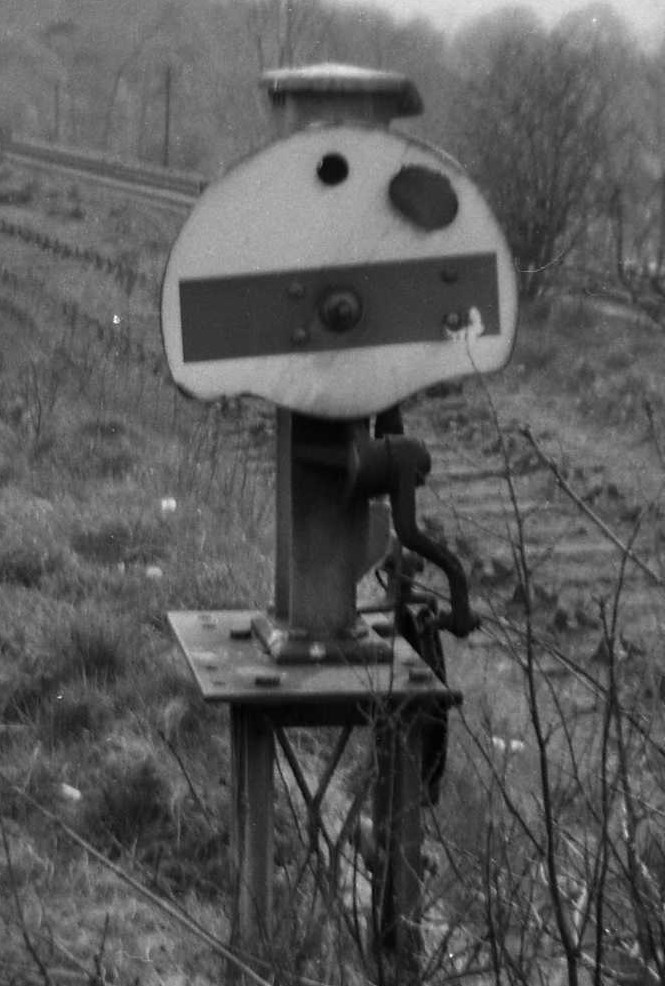
 'Half-Disc'
& 'Full-Disc' Ground Signals. From later SR days onwards many ground signals were replaced by the standard SR Westinghouse
'half-disc' pattern (PRSS Fig 20), which essentially was
the same signal as the 'miniature semaphore' type but with a half-disc faceplate
instead of a rectangular arm. By the time that the S&DJR closed to all
passenger traffic in 1966 most - though by no means all - of its ground
signals had been replaced by the 'half-disc' type. However in BR days two of
the ground signals at Midsomer Norton were replaced (at different dates) by examples of the BR(WR) pattern
'full disc' ground signal and a further example was fitted onto an existing bracket
signal at Highbridge during layout alterations in 1965. It is possible
that there may have been other examples of BR(WR) 'full disc' ground signals which have escaped the
photographic record.
'Half-Disc'
& 'Full-Disc' Ground Signals. From later SR days onwards many ground signals were replaced by the standard SR Westinghouse
'half-disc' pattern (PRSS Fig 20), which essentially was
the same signal as the 'miniature semaphore' type but with a half-disc faceplate
instead of a rectangular arm. By the time that the S&DJR closed to all
passenger traffic in 1966 most - though by no means all - of its ground
signals had been replaced by the 'half-disc' type. However in BR days two of
the ground signals at Midsomer Norton were replaced (at different dates) by examples of the BR(WR) pattern
'full disc' ground signal and a further example was fitted onto an existing bracket
signal at Highbridge during layout alterations in 1965. It is possible
that there may have been other examples of BR(WR) 'full disc' ground signals which have escaped the
photographic record.
[Note: it is important to understand that the style of symbol used to denote a 'ground signal' on a S&DJR signal diagram was not necessarily representative of the actual design of signal installed at that location. Signal diagrams were drawn or altered using whatever type of symbol was 'standard' at the time, regardless of what design of signal was actually 'on the ground', so it is not unknown therefore for a signal diagram to contain more than one type of ground signal symbol. Similarly diagrams were not updated simply to reflect the replacement of an old ground signal by a newer version, so it is not unknown for diagrams to show all their ground signals as an older type long after they had been replaced by a newer design. It is unwise therefore to regard any signal diagram as an accurate representation of the precise style(s) of ground signal actually in use at the relevant location.]
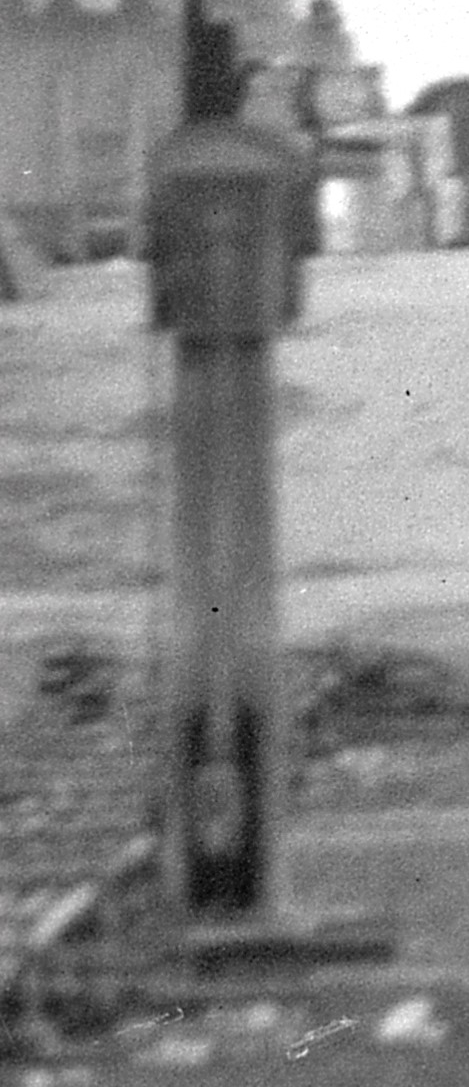 Elevated
Ground Signals. As mentioned above, some 'ground' signals in fact were raised above ground
level for sighting purposes, particularly in places where it was necessary for
the signal to be visible by the driver of an engine at the far end of a long
train stood in rear of the signal and/or there was some intervening obstruction
such as a platform. In some places the ground signal was elevated on its own
post, in other locations it might have been placed on a bracket part of the way
up the post of an adjacent main running signal; some examples of the latter
practice can be seen in the photograph in the Introduction
to this page. One interesting variation was signal 11PUSH at Edington Junction,
which was a Stevens 'flap' signal constructed with a 'pillar' that was much taller than normal,
as shown here on the right in a view taken from behind the signal (click photo for a rather poor quality enlargement).
Elevated
Ground Signals. As mentioned above, some 'ground' signals in fact were raised above ground
level for sighting purposes, particularly in places where it was necessary for
the signal to be visible by the driver of an engine at the far end of a long
train stood in rear of the signal and/or there was some intervening obstruction
such as a platform. In some places the ground signal was elevated on its own
post, in other locations it might have been placed on a bracket part of the way
up the post of an adjacent main running signal; some examples of the latter
practice can be seen in the photograph in the Introduction
to this page. One interesting variation was signal 11PUSH at Edington Junction,
which was a Stevens 'flap' signal constructed with a 'pillar' that was much taller than normal,
as shown here on the right in a view taken from behind the signal (click photo for a rather poor quality enlargement).
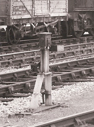
 Where the signal had its own post that might be quite short - perhaps just a couple of
feet high - and it could be an actual length of lattice post (similar to that used
for main running signals) or just some form of fabricated 'stand' (see examples
shown on the left here). Other signals could be quite tall and one such example was
installed on a lattice post at Radstock East in 1926 and was 16 feet above rail
level! With most of the 'low' examples however there was usually nothing on the
signal-box diagram to indicate that a ground signal was indeed 'elevated' in
some way and so that fact has become apparent only when a photograph of the signal
has come to light. Consequently there may in fact have been more 'elevated'
ground signals on the S&DJR than have been recorded so far.
Where the signal had its own post that might be quite short - perhaps just a couple of
feet high - and it could be an actual length of lattice post (similar to that used
for main running signals) or just some form of fabricated 'stand' (see examples
shown on the left here). Other signals could be quite tall and one such example was
installed on a lattice post at Radstock East in 1926 and was 16 feet above rail
level! With most of the 'low' examples however there was usually nothing on the
signal-box diagram to indicate that a ground signal was indeed 'elevated' in
some way and so that fact has become apparent only when a photograph of the signal
has come to light. Consequently there may in fact have been more 'elevated'
ground signals on the S&DJR than have been recorded so far.
S&DJR Signal Instruction 284 records the provision of two ground signals on the Lower Road at Templecombe No 3 Junction on 23-June-1927 which were elevated on posts 2½' high and intended to act as 'repeaters' for an existing pair of ground signals further ahead, but nothing further is know about them other than that they were abolished during subsequent layout alterations on 12-February-1933 (Signal Instruction 328). Those 1933 alterations also included the provision of four new elevated ground signals on the Lower Road, two on individual posts and two side-by-side on a bracket, all four signals being 17½' above rail level.
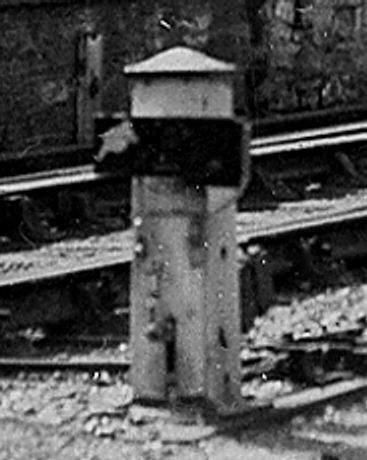
 In addition to the two examples (described
above) of 'miniature arm' ground signals
elevated on short posts at Evercreech Junction North, there
were a further two 'elevated' ground signals (15PUSH and 16PULL)
adjacent to the Up Main at Evercreech Junction South. It is not known
when these were installed, but certainly they were in existence by 1907 as
Signal Instruction 196 states that "...the
present two-armed bracket disc signal..." was to moved be 20 yards
further out on 6th October that year. Their original style is unknown, but at that
date they may have been simply a pair of normal 'flap' signals, although by
late BR days they were a pair of 'half-disc' signals located side-by-side on a
small bracket on top of a tall post which appears to have been of
the S&DJR rail-built type (click
photo to
see a larger image). The elevation of those discs was enhanced by the fact
that the bracket was sited adjacent to the up marshalling sidings on
land which was at a higher level than the Up Main.
In addition to the two examples (described
above) of 'miniature arm' ground signals
elevated on short posts at Evercreech Junction North, there
were a further two 'elevated' ground signals (15PUSH and 16PULL)
adjacent to the Up Main at Evercreech Junction South. It is not known
when these were installed, but certainly they were in existence by 1907 as
Signal Instruction 196 states that "...the
present two-armed bracket disc signal..." was to moved be 20 yards
further out on 6th October that year. Their original style is unknown, but at that
date they may have been simply a pair of normal 'flap' signals, although by
late BR days they were a pair of 'half-disc' signals located side-by-side on a
small bracket on top of a tall post which appears to have been of
the S&DJR rail-built type (click
photo to
see a larger image). The elevation of those discs was enhanced by the fact
that the bracket was sited adjacent to the up marshalling sidings on
land which was at a higher level than the Up Main.
Repeater Ground Signals. There were a few known instances on the S&DJR where, in order to improve the sighting distance of existing ground signals, additional 'repeater' ground signals were installed some distance in their rear. One such installation was at Templecombe 'B' box, where a pair of ground signals (Nos 5PULL and 9PULL) on the Up line of the sharply-curved connecting spur to Templecombe No 2 Junction were provided with a pair of 'repeater' ground signals some distance further away around the curve; photographic evidence suggests that both sets of signals were of the Stevens 'flap' type. As mentioned above in the notes about 'elevated' ground signals, two 'repeater' ground signals (elevated on posts 2½' high) were installed on the Lower Road at Templecombe No 3 Junction on 23-June-1927 (S&DJR Signal Instruction 284), but subsequently abolished during layout alterations on 12-February-1933 (Signal Instruction 328); it is not known what type of ground signals was used in that instance, but by that date they would probably have been of the Westinghouse 'miniature arm' type.
At Templecombe No 2 Junction ground signal 30PUSH was sited adjacent to the Down Main at the toe of crossover points 12 in front of the signal-box. In that position it applied both to trains reversing from the Down Main (on the 'spur' leading to Templecombe 'Upper' station) and also to Up trains coming off the single-line from Henstridge. A 'repeater' ground signal was provided on the Down Main 74 yards in rear of 30PUSH, but no similar repeater was provided on the single-line; consequently the 'repeater' ground signal operated only when the junction points 11 (located between 30PUSH and its repeater) were set 'normal' for the Down Main and not when they were reversed for the single-line. However this unusual 'conditional' arrangement ceased at some unknown date between 1948 and 1953 when the ground signal at points 12 was abolished, after which 30PUSH worked only the former 'repeater' on the Down Main 'spur' and no longer applied to Up trains coming off the single-line.
In the 1933 alterations at Corfe Mullen Junction a 'repeater' ground signal (No 13R) was installed 190 yards in rear of the new ground signal No 13 and this was of the 'yellow' Westinghouse miniature arm type. With the exception of the 'yellow arm' used at Corfe Mullen Junction, it not known whether any of the other 'repeater' ground signals were identified specifically as repeaters in any way. In all known cases the 'repeater' ground signal was worked by the same lever in the signal-box as that of the ground signal which it repeated.
| Miscellaneous Indicators etc |
In addition to the 'point indicators' described in the section on ground signals above, the S&DJR also had a few examples of other types of 'indicators' that were fixed at the side of the track. Some of these were more akin to fixed notices rather than workable signals, but as most were related in some way to train movements it would seem appropriate to include a few notes about them on this page.
Bridge Indicator. No description of S&DJR signalling would be complete without a mention of the curious 'Bridge Indicators' which existed at Corfe Mullen Junction in the early 1900s. Unfortunately, as described here, there are no known details of these mysterious items, which may not have been directly involved with the signalling of trains anyway. However, as these indicators were worked from the signal-box lever-frame, they were more akin to 'signals' than the Trap Points and Limit of Shunt indicators described below, which essentially were just fixed notice-boards.
 Trap Points Indicator. In 1939
(Signal Instruction 380) a 'Trap Points'
indicator (TPI) was provided at Shillingstone at the
exit from one of the sidings in place of an older 'point disc'. In essence it was a
rectangular 'box' with an opaque glass screen at the front, bearing the words
'TRAP POINTS' (probably in red, similar to the LOS indicators) and illuminated
from behind by an internal oil lamp (click picture for a larger image). This was the only known TPI on the
S&DJR and it is unclear why it was provided for that particular siding, given
that there were other S&DJR locations which had trap-points without any TPI,
point disc or shunt
signal.
Trap Points Indicator. In 1939
(Signal Instruction 380) a 'Trap Points'
indicator (TPI) was provided at Shillingstone at the
exit from one of the sidings in place of an older 'point disc'. In essence it was a
rectangular 'box' with an opaque glass screen at the front, bearing the words
'TRAP POINTS' (probably in red, similar to the LOS indicators) and illuminated
from behind by an internal oil lamp (click picture for a larger image). This was the only known TPI on the
S&DJR and it is unclear why it was provided for that particular siding, given
that there were other S&DJR locations which had trap-points without any TPI,
point disc or shunt
signal.
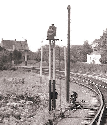
 Limit of Shunt Indicator. In 1933 'Limit of Shunt' (LOS)
indicators were provided at Corfe Mullen Junction (Signal Instruction 338) and the former
Templecombe No 3 Junction (Signal Instruction 328). Limited photographic evidence would
suggest that essentially they were identical in form to the Trap Points
indicator shown above, with an opaque screen illuminated from behind, except
that the wording read 'LIMIT OF SHUNT' in red letters (according to the relevant
Signal Instructions) placed on three lines. The purpose of a LOS was to mark the limit
of 'wrong direction' shunting movements, acting in effect as a permanent 'stop'
signal. No other S&DJR examples are known to have been provided.
Limit of Shunt Indicator. In 1933 'Limit of Shunt' (LOS)
indicators were provided at Corfe Mullen Junction (Signal Instruction 338) and the former
Templecombe No 3 Junction (Signal Instruction 328). Limited photographic evidence would
suggest that essentially they were identical in form to the Trap Points
indicator shown above, with an opaque screen illuminated from behind, except
that the wording read 'LIMIT OF SHUNT' in red letters (according to the relevant
Signal Instructions) placed on three lines. The purpose of a LOS was to mark the limit
of 'wrong direction' shunting movements, acting in effect as a permanent 'stop'
signal. No other S&DJR examples are known to have been provided.
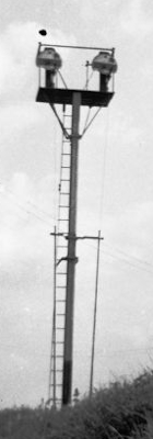
Marker Light. At an unknown date in the
early 1950s all the main running signals at Henstridge were abolished. Two
white 'marker lights' were provided at the approach to the
station, one each for the Up and Down directions; it is probable, but
not confirmed, that these were fitted to the posts which previously had carried
the Up and Down Distant signals. In the absence of any photographic record the
style of these lights is unknown, but probably they were just simple
plain lamps similar to those used for signals. It is believed that these
marker lights were provided purely to enable the drivers of approaching trains
to establish their location relative to the station (once the former Distant
signals had been removed) and did not have any signalling function at
all (but they have been included in this page for convenience), but it is not
known if any 'lamp repeaters' were provided
anywhere to indicate that the lights were proven to be lit.
In July 1966 there were various alterations to the remaining goods-only section of the S&DJR from Blandford to Broadstone, which are described in BR(SR) Weekly Notice P/EW27 (click here to see the relevant extracts). Those changes included the provision of white marker lights on the posts of the following former Distant signals:- Blandford Up Distant, Bailey Gate Down Distant and Up Distant, Bailey Gate Crossing Down Distant, Corfe Mullen Junction Up Distant and Broadstone Down Branch Distant. No other examples of 'marker lights' are known to have existed anywhere else on the S&DJR.
[Note: there is no mention in P/EW27 of 1966 of any marker lights on either the Up Distant at Bailey Gate Crossing or the Down Distant at Corfe Mullen Junction. One may speculate that, as a result of the relatively close proximity of those two locations, the provision of one marker light only in each direction was considered sufficient.]
Finally...
![]() ...an
audible signal! There were occasions when a signalman might
need to send instructions about train movements to a shunter at a busy, noisy yard. In the days before the
widespread provision of track-side telephones, one
method of communication was the provision of a mechanical gong. This would
be mounted on a post at a convenient location near the track and operated by
wire from a lever in the signal-box. Each stroke of the lever would cause a
striker to hit the gong once, so a code of 'beats' would be used to convey
different messages. There was one known gong on the S&DJR, which was
sited in the Lower yard at Templecombe No 2 Junction, and the
picture shows a rear view of it in BR days (click picture for a larger image).
...an
audible signal! There were occasions when a signalman might
need to send instructions about train movements to a shunter at a busy, noisy yard. In the days before the
widespread provision of track-side telephones, one
method of communication was the provision of a mechanical gong. This would
be mounted on a post at a convenient location near the track and operated by
wire from a lever in the signal-box. Each stroke of the lever would cause a
striker to hit the gong once, so a code of 'beats' would be used to convey
different messages. There was one known gong on the S&DJR, which was
sited in the Lower yard at Templecombe No 2 Junction, and the
picture shows a rear view of it in BR days (click picture for a larger image).
© CJL Osment 1998-2026
Acknowledgements to David Over, John Palmer and Alan Price for additional information. Highbridge
bracket signals photograph © Edward Dorricott, S&DJR rail-post signal and Westinghouse 'red arm' ground signal photographs
courtesy Duncan Chandler collection, Moorewood distant arm photograph © Alan Price,
Glastonbury Down Distant signal photograph © John Palmer, Highbridge twin 'flap' signals photograph © Roger Merry-Price courtesy John
Creed, 'flap' signal with extended pillar photograph courtesy Derek Phillips, TPI photograph courtesy
Bluebell
Railway Museum Archive (Alan Postlethwaite collection) and signal graphics courtesy John Hinson.
All other images WCRA collection.
References
|
© West Country Railway Archives 2004 Page last updated: 14 March 2026 |
URL:
E-Mail: |
||||||


