


 |
Somerset &
Dorset Joint Railway Signalling at Glastonbury and Wells Branch Junction |
|
||||||||
|
||||||||||
Glastonbury station was situated on the branch of the Somerset & Dorset Joint Railway (S&DJR) from Evercreech Junction to Highbridge in the county of Somerset. It was also the junction station for the S&DJR branch to Wells.
Glastonbury station was opened on 28-August-1854 as the terminus of the Somerset Central Railway (SCR), a broad-gauge (7' 0¼") line running eastwards from a junction with the Bristol & Exeter Railway (B&ER) at Highbridge. Within four years work had begun on extending the line at both ends, with the westwards extension from Highbridge to Burnham opening on 3-May-1858 and the eastwards extension from Glastonbury to Wells a year later on 15-March-1859.
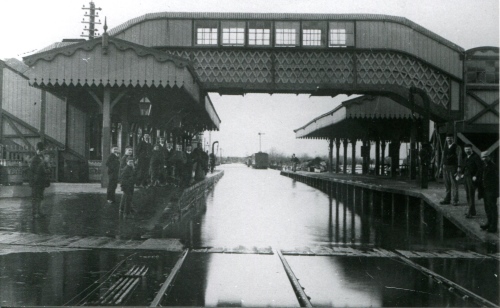
Glastonbury station looking west during floods pre-1901
The SCR then began another extension from Glastonbury eastwards towards Bruton, with the aim of meeting up with the northwards expansion of the Dorset Central Railway (DCR) from Wimborne. This extension was constructed as standard gauge (4' 8½"), with the existing SCR system becoming mixed gauge, and it was opened on 3-February-1862. Shortly afterwards the DCR and SCR amalgamated and on 1-September-1862 formed the Somerset and Dorset Railway (S&DR). The broad gauge fell into disuse and was removed from the S&DR system about 1870. The S&DR eventually became the S&DJR in 1875 when the line was leased jointly by the Midland Railway (MR) and London & South Western Railway (L&SWR).
When the Bruton extension was constructed it diverged from the Wells extension about a mile north-east of Glastonbury, at a location known subsequently as Wells Branch Junction. However Glastonbury itself was the actual interchange station for the two lines, the trains to and from Wells and West Pennard (the first station eastwards on the Bruton extension) traversing the same single line as far as Wells Branch Junction. Naturally this remote junction had to be manned and the various references contained within the 1864 S&DR Rule Book give an interesting example of contemporary S&DR signalling practice.
The 1864 S&DR Rule Book stated:-
WELLS BRANCH JUNCTION All trains approaching this Junction from Wells, or from West Pennard, are to stop fifty yards short of the Points. No Train, under any circumstances, must pass the Junction from either end, unless accompanied by the Pilotman appointed for that purpose, and who is distinguished by a broad red badge on the right arm. When there are two Trains to pass over the Junction in the same direction, the Pilot must accompany the first Train on to the Junction, and, having despatched it, must wait for the second, and then proceed to Glastonbury. The second Train must not be passed over the Junction until the Pointsman in charge receives a telegram from Glastonbury that the first Train is in. The Pilotman will then accompany the Train over the Points and into Glastonbury, unless another Train is due at the Junction. He will in all cases accompany the last of such Trains to Glastonbury. The Trains from Glastonbury are to be worked over the Junction in the same manner. Any departure from the Regulations will subject the offender to instant dismissal, and will render him liable to prosecution for having either wilfully or carelessly obstructed the working of the Line. When two Trains arrive at the Junction at the same time, precedence in all cases is to be given to the Wells Branch Trains, and to Passenger Trains over Goods Trains. |
A subsequent amendment stated that these rules would be "suspended until further notice" with effect from 8-April-1867, after which "All Trains must be worked over this Section of the Line on the Block System of Telegraphing, and in strict accordance with the Instructions contained in Section 3, page 19, of the Company’s Book of Rules and Regulations". The precedence for trains at Wells Branch Junction remained as before. A later notice read as follows:-
WELLS JUNCTION & GLASTONBURY --------- The following Special Regulations for crossing Trains out of their ordinary course are applicable to the Wells Branch Junction and Glastonbury ONLY. --------- When TRAINS MARKED in the Working Time Book TO CROSS AT THE JUNCTION ARE REQUIRED TO CROSS at GLASTONBURY, the following Rules are to be observed, viz:- Glastonbury will give SIX distinct strokes of the Bell, which are to be REPEATED by the Signalman at the Junction, who must AFTERWARDS obtain "LINE CLEAR" in the USUAL MANNER, and then send on the Train into Glastonbury giving to the Driver a signed order to proceed on the form supplied for that purpose, which shall be his authority for proceeding accordingly. When TRAINS MARKED in the Working Time Book TO CROSS AT GLASTONBURY, ARE REQUIRED TO CROSS AT THE JUNCTION, the following Rules are to be observed, viz:- Glastonbury will give TEN distinct strokes of the Bell, which are to be REPEATED by the Signalman at the Junction. Glastonbury must AFTERWARDS obtain "LINE CLEAR" in the USUAL MANNER, and then send on the Train to cross there; giving the Driver a signed order to proceed on the form supplied for that purpose, which shall be his authority for proceeding accordingly. |
It is evident from these instructions that Wells Branch Junction had a signalman and presumably some form of shelter would have been provided for him and the equipment at that isolated place. However nothing is known about the actual layout (which may have been little more than a single point) nor the details of any signals, although it would appear that at least some disc-and-crossbar signals were provided as their subsequent removal in 1878 is mentioned in S&DJR Signal Instruction 17 (see below). It is unlikely that a proper signal-box with a lever-frame existed, as Minute 381 of the S&DJR Officers' meeting on 8-November-1876 (National Archives file RAIL 626/16) records a decision for "Wells Junction, Glastonbury to be interlocked" at a cost of £250. At a subsequent meeting on 9-March-1877 (Minute 508) it was decided that the "resignalling of Wells Branch Junction near Glastonbury" (apparently now at a cost of £190) was to be deferred so, in view of the subsequent demise of the junction in December 1878, it would seem unlikely that in fact any such work was done.
At Glastonbury itself the early history is very vague and apart from the material about Wells Branch Junction there appear to be very few signalling references prior to 1878. The earliest known record is a copy in National Archives file MT6/11/91 of B&ER "Instructions to Head Guards and all others concerned in the working of the single line between Glastonbury and Highbridge" dated 16-September-1854. The gist of these instructions was that no train was to move over the line without the guard (who was nominated specifically on a daily basis) on board, the implications being that the whole branch at that time was worked as a single block section with a form of 'Pilot Guard' working (click here to see the full text).
S&DJR Officers' Minute 373 for 8-November-1876 contains an entry about Glastonbury, stating that "a signal-box to be provided at the north end of the Glastonbury goods yard...points to the goods yard and north end of the loop to be worked from it...present signals to be removed and new signals provided...points at the south end of the loop to be bolt-locked from the new box and worked from the ground box as at present. Block to terminate at the box at either end of the station...bell and gong communication to be provided". The estimated cost was £680. It is not known what or where the 'ground box' was, nor whether the 'new box' was intended to replace any other existing signal-box, and the reference to ’block to terminate...at either end of the station’ is also confusing. It is unclear also whether these alterations actually took place at that time and in the form described, given that two years later the layout was revised and a new signal-box (SB) was constructed that worked both ends of the loop (see below).
In 1878 the layout at Glastonbury was re-organised with the construction of an additional line alongside the existing track from the station to Wells Branch Junction, which was abolished on 7-December-1878 (S&DJR Signal Instruction 17). After that date the Wells and Evercreech Junction branches had independent tracks east of Glastonbury, without any physical connection at their divergence at the site of the former Wells Branch Junction. The station now had a passing-loop with platforms on each line, the Down platform being an island platform whose outer face served a loop that acted as a bay platform for trains on the Wells Branch, all controlled from a new signal-box constructed at the Highbridge end of the Up platform.
The new 1878 SB contained a 22-lever interlocking frame (19 working and 3 spares). The work was inspected for the Board of Trade (BoT) by Major Marindin and his Inspection Report dated 16-December-1878 can be found in National Archives file MT6/218/10, which includes the signal diagram shown below. In his Report the Major requested the provision of a trap-point and disc signal at the end of the 'Wells loop'; it is not known when these were provided nor what alterations were made to the frame to accommodate these, but one must assume that the diagram below represents an arrangement that did not exist unchanged for very long.
| Glastonbury 1878 SB photo circa-1890s |
Glastonbury 1878 signal diagram | |
 |
 |
|
| Click photo for larger image | Click diagram for larger image |
There is some mystery about the construction of the new 1878 SB. There is an old photograph (see above) of the front of the SB, probably taken in the 1890s, which shows the box as a S&DJR TYPE 2 design, but unusually the timber superstructure had outside framing and extended lower down at the front than normal. It is possible that the SB had less stone or brick in its construction than others of its type because of ground loading problems - certainly most buildings at the station were of timber (although the nearby former S&DJR offices were brick). A distant view of the rear and station end of the SB can be seen in a photograph on page 101 of the OPC "An Historical Survey of the Somerset & Dorset Railway" [Ref 1], and it would appear that at least there was a brick chimney stack at the rear. In the absence of any other evidence, it must be assumed that the SB illustrated in those photographs was the one erected in 1878, which would make it the first of its Type; this is curious, because it would have been erected towards the end of a period (1876-9) of building S&DJR Type 1 SBs, and no other Type 2 SBs are known to have been erected before the mid-1880s.
At the eastern end of the station there was a level-crossing over Dyehouse Lane and a hut was provided there for the gate-keeper. Further east between Glastonbury and the site of the former Wells Branch Junction there was a level-crossing at 9 miles 39 chains known as Cemetery Lane; this had a house on the Down side for a resident crossing-keeper, and there is an unconfirmed contemporary recollection that it also had a small hut, but there was no signalling at that location. Both of those crossings now accommodated two parallel single-track lines. It is not known exactly when facilities were provided for a crossing-keeper at Cemetery Lane and that may have occurred before or after 1878, but it would seem appropriate to mention them at this stage. At the western end of the station, immmediately beyond the ends of the sidings which extended beyond the west end of the passing-loop, the single-line passed over the un-manned Middle Drove occupation crossing. Further west at 11 miles 6 chains lay Aqueduct Crossing, which is believed to have had just a small hut for a crossing-keeper originally, but a house was added at a later date on the Down side; there was no signalling at that location. Click here for a track plan of Glastonbury in 1904.
[Note: the crossing known as Cemetery Lane by the S&DJR was actually on Lowerside Lane, which leads to the local cemetery. There is unconfimed anecdotal evidence that (at least at one time) its nameboard read Cemetary Lane. There is a reference to Paradise crossing as an alternative name for Dyehouse Lane crossing, presumably as the area to the north-east is marked as 'Paradise' on some old maps.]
In 1901 further changes took place at Glastonbury and on 3rd June that year a new SB was opened adjacent to the earlier box (S&DJR Signal Instruction 142). The new SB contained a 27-lever Stevens-pattern 4.1/8"-centres interlocking frame (of unknown manufacture) and was built to the S&DJR TYPE 3 design with a hip roof, although curiously again it was one of the few Type 3 SBs to be constructed entirely of timber (which may reinforce the suspicions about ground loading mentioned above). The SB seems to have been rather longer than was necessary for the size of lever-frame, but one can only speculate whether this implies some unknown plan for future expansion or merely the convenient use of 'standard' panel sizes.
| Glastonbury 1901 signal-box (photo date unknown) |
Glastonbury 1901 signal diagram | |
 |
 |
|
| Click photo for larger image | Click diagram for larger image |
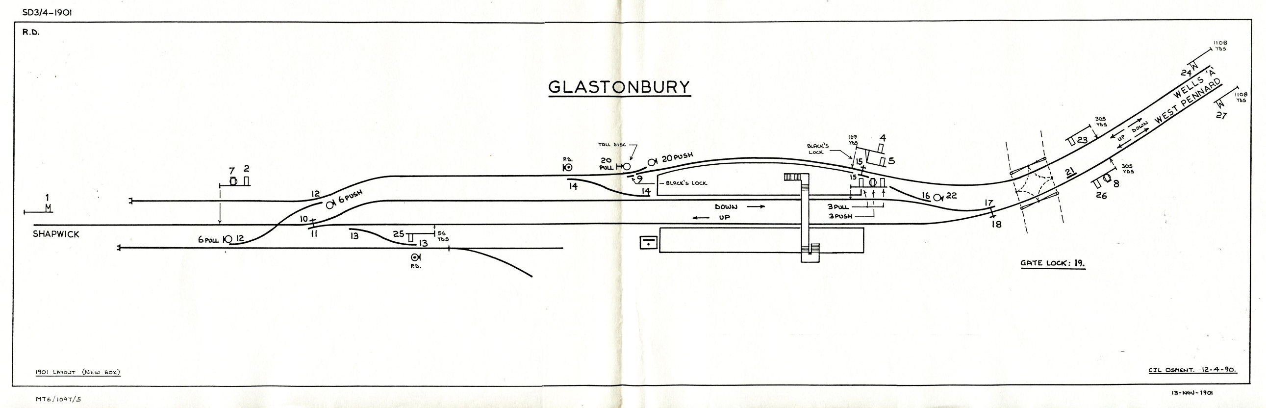
The new works were inspected for the BoT by Major Pringle and his Inspection Report of 30-December-1901 can be found in National Archives file MT6/1097/5 together with the signal diagram shown above. Two items worthy of note here are the provision on points 9 and 15 of "Black's Locks", which were a form of 'economic' FPL widely used by the L&SWR, and the existence of a 'safety bar' 21 on the main line to the east of the level-crossing gates. This bar served a 'route holding' function while an Up train traversed the distance from signal 26 to the commencement of the lock bar worked by FPL 18; the safety bar was removed at some unknown date between 1930 and 1950 (circumstantial evidence suggests possibly in late 1949) and lever 21 was spare thereafter.
Major Pringle refers in his Report to the provision of the new SB with 27 levers (including 3 'push-pull'), 2 new 'draw ahead' signals (assumed to be 7 and 8, although it is not known when 3PUSH was provided), and catch points (presumably 9) on the 'dead-end siding' at the end of the Wells loop. However he called for the provision of 'entrance discs' for points 13 and 14 and also for the 'point discs' (marked 'PD' on the diagram) to be worked from the SB. This work involved the extension of the frame by a further two levers, and apparently also the conversion of an existing lever to 'push-pull' working, as in his further Inspection Report dated 24-July-1902 he records the frame as being then of 29 levers including 6 push-pull. Unfortunately no diagram exists to show the revised layout, but from later information it would appear that the frame extension was carried out by adding one extra lever at each end.
There is limited coverage of Glastonbury in surviving S&DJR Signal Instructions (SI), the first one being SI 186 which records that on 3-November-1905 the ground signal reading from the Down Siding to the Down Loop was to be moved into the 'six foot'; this presumably was the signal adjacent to points 14 that originally was a 'point disc' in the 1901 diagram. However it is fortunate that a copy survives of SI 300, as this records the details of a series of significant changes which occurred at Glastonbury in 1929. On 27-December-1929 the Down Distant was moved about 428 yards nearer to Ashcott, whilst the next day saw the following alterations:-
the Down Home was moved 154 yards further from the SB and the Down 'Calling On' arm was abolished
a new Up Advanced Starting signal 15' high was provided 263 yards ahead of the Up Starting
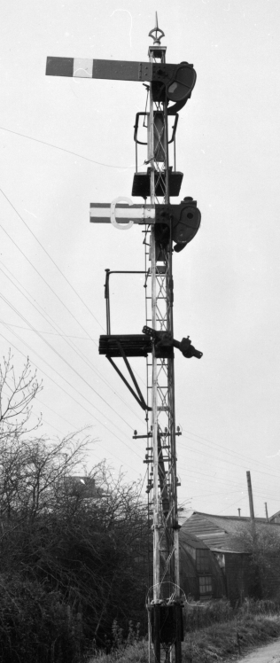
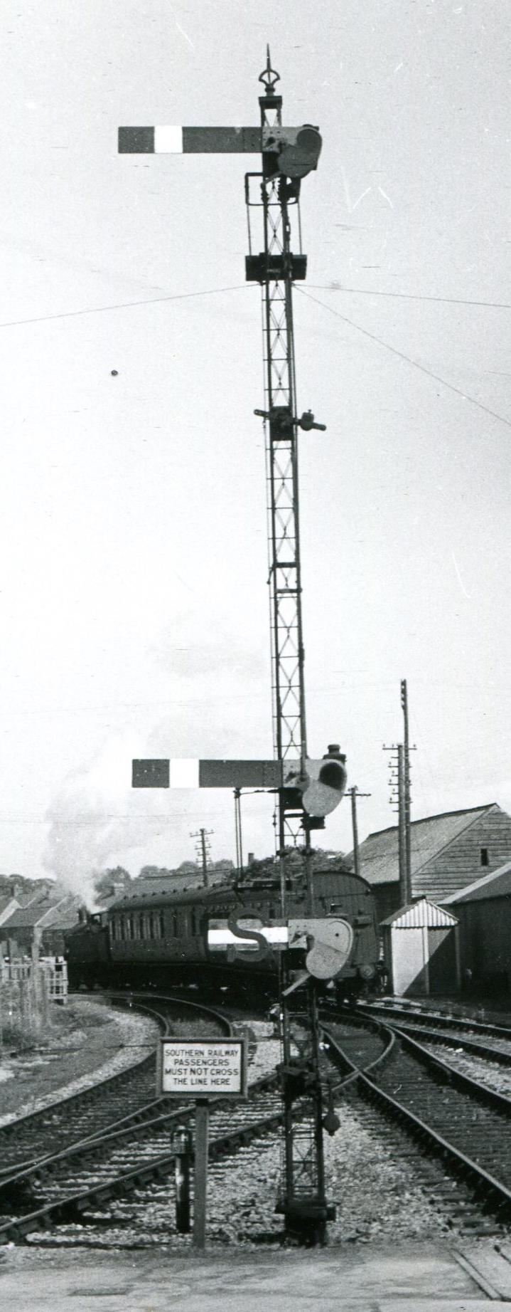
the ringed arm of the Down 'Shunt-By' signal was replaced by an horizontally-striped arm with red letter 'S'
the ringed arm of the Up 'Calling On' signal was replaced by an horizontally-striped arm with red letter 'C'
existing points 13 were abolished and a new connection provided from the Up Siding to the single line at the Ashcott end of the station, together with a new ground signal adjacent to the single line
ground signals 6PULL, 6PUSH, 8PULL and 7PULL were all re-located, the first three being fitted with yellow miniature semaphore arms.
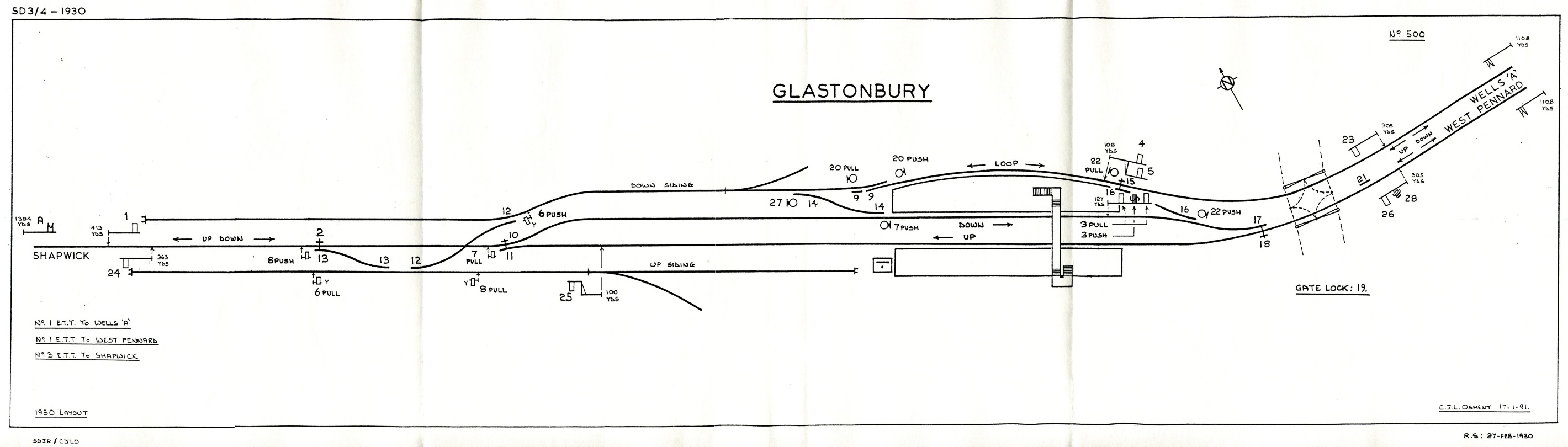 |
| Glastonbury Signal Diagram
1930 Click diagram for larger image |
 The
results of all those changes can be seen in the
signal
diagram shown above, which is taken from a S&DJR copy stamped
27-February-1930. Comparison with the
1901
diagram will show the addition of levers A and 28 (believed to have
happened in 1902), and also that there have been some other minor
alterations at some time (eg the abolition of the Black's Lock on points
16 and the addition of ground signal 22PULL), but dates for these
changes are unknown. After the 1929 changes ground signals 7PULL and
8PULL both became 'running shunts' - in other words they had to be
pulled 'off' before the Down Home signal (1) could be cleared for
running movements along the Down Main. SI 300 stated that the relocated
Down Home was now 1000 yards from the Down Distant, but this may have
been only an approximate intention, as distances given in the 1930
diagram are taken from the S&DJR original and are believed to be
correct.
The
results of all those changes can be seen in the
signal
diagram shown above, which is taken from a S&DJR copy stamped
27-February-1930. Comparison with the
1901
diagram will show the addition of levers A and 28 (believed to have
happened in 1902), and also that there have been some other minor
alterations at some time (eg the abolition of the Black's Lock on points
16 and the addition of ground signal 22PULL), but dates for these
changes are unknown. After the 1929 changes ground signals 7PULL and
8PULL both became 'running shunts' - in other words they had to be
pulled 'off' before the Down Home signal (1) could be cleared for
running movements along the Down Main. SI 300 stated that the relocated
Down Home was now 1000 yards from the Down Distant, but this may have
been only an approximate intention, as distances given in the 1930
diagram are taken from the S&DJR original and are believed to be
correct.
There was a further minor change on 20-December-1931 (SI 319) when two ground signals (apparently 20PULL and 27 from the descriptions given) were each moved 5 yards further from the SB. Then on 10-June-1934 (SI 350) the Down Starting signal (3PULL) was provided with a new post 34' high, still with two co-acting arms, and at the same time the Shunt Ahead arm (3PUSH) was relocated further down the post below the lower co-acting arm. It was probably at this time that the original wooden post was replaced by the later lattice post and the revised signal configuration (see right-hand picture) provides a useful reference for dating the many photographs taken at the east end of the station. The left-hand picture shows the Up Home signal (26) and its subsidiary Calling On arm (28). On 15-April-1945 the Down Home signal (1) was renewed at 25' high.
The gates at Dyehouse Lane level-crossing were worked by hand by a crossing-keeper and it is believed that lever 19 in the SB worked directly on the Gate Locks. A plan from the British Railways period marks a 'wickets lever' ground-frame outside the hut, but a copy of the signal diagram circa-1963 (more about this here) mentions levers in the hut working the Gate Stops and the Wickets. The crossing hut was on a local telephone circuit (BR(WR) No 794) which included the SB, the station ticket office and Cemertery Lane crossing.
Official records become very scarce again after the early-1930s but it is believed that the overall arrangement continued unchanged, with the possible exception of the removal of the safety bar 21 as mentioned above. On 31-December-1949 (according to a S&D Special Notice) the loop line was renamed 'Wells Loop' and ground signal 20PULL was abolished, its function being combined with signal 27.
The next substantial change came on 29-October-1951 with the complete closure of the Wells Branch. As a result signals 4, 5, 23 and the 'from Wells' fixed distant were abolished, as were ground signal 20PUSH and trap points 9. The 'Wells Loop' end of crossover 16 was retained as a trap-point along with signal 22PULL, but FPL 15 was abolished. It is unclear exactly how soon these changes took place, as there was a reference to the branch being "retained as a head-shunt" and the actual track was not lifted until 1955-57. A subsequent Weekly Notice refers to some unspecified 'signal alterations' during the period 23/28-November-1958; the implications are unclear, but may perhaps relate to some of the changes mentioned below.
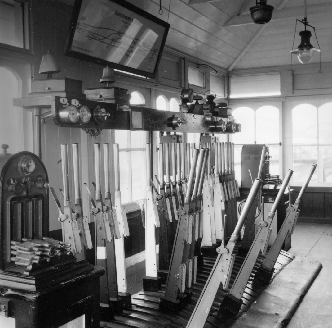
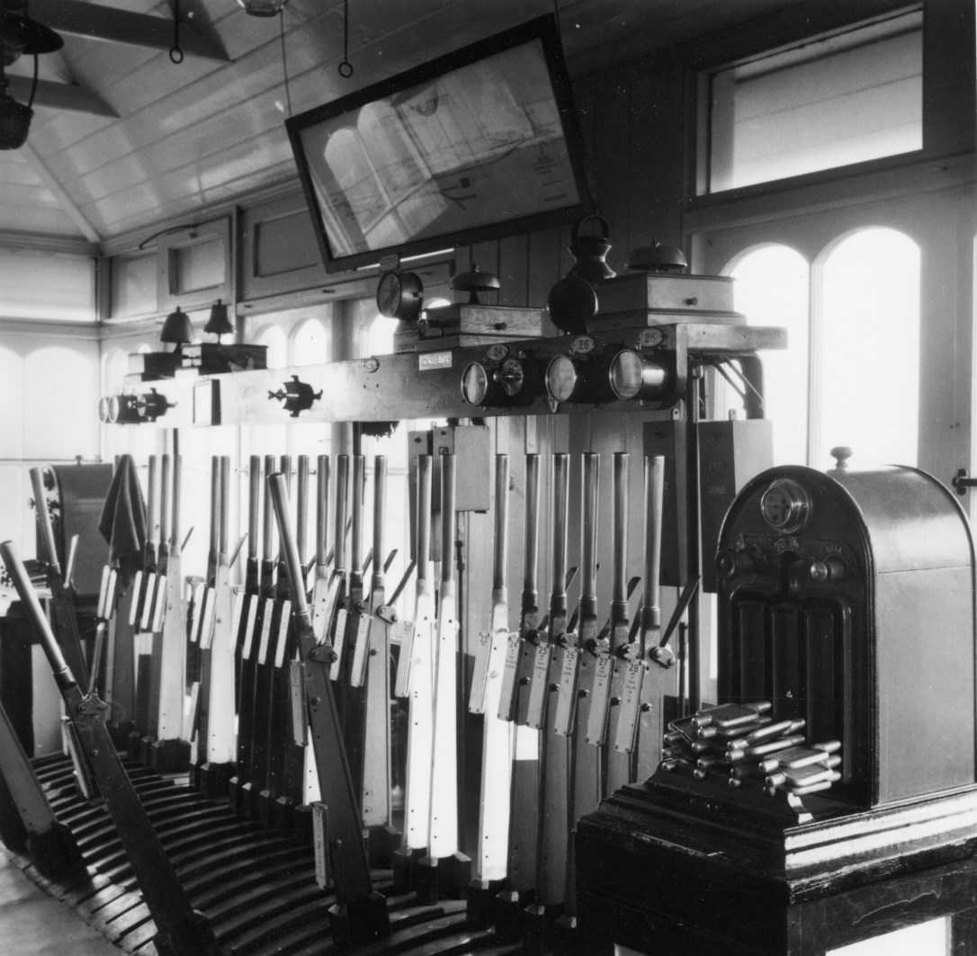
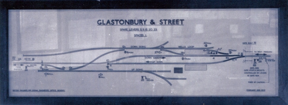
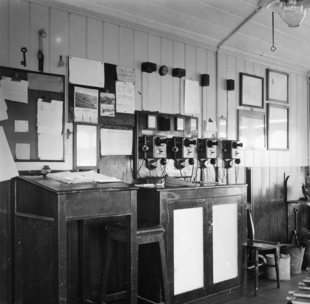
| Interior of Glastonbury signal-box circa-1962 | ||||||
 |
 |
 |
 |
|||
| Looking from left to right | Looking from right to left | Signal Diagram | View of the back wall | |||
| Click on the thumbnails to see larger images | ||||||
Some photographs were taken inside Glastonbury SB circa-1962 by the late David Milton (see above - click the thumbnails for larger images). Two of these show the lever-frame and at each end the Electric Key Token instrument for the adjacent single-line block section (see below for more details on the block working at Glastonbury). The SB diagram at that time was of British Railways (Western Region) origin and the master copy was dated February 1959, but it is not known what had prompted BR(WR) to produce a new diagram at that time. The photograph of the WR diagram shows that the original version contained some errors, as lever 1 was marked correctly as working the Down Home but it was listed also as being a 'space', whereas spare lever 21 was not listed at all. Furthermore disc 6PUSH appears not be marked as a 'yellow' disc any more, and the subsidiary 'Shunt Ahead' arm on the post of the Down Starting signal was shown between the two co-acting main arms rather than at the bottom of the post. However the master drawing was corrected later and a revised version was installed in the SB sometime prior to closure.
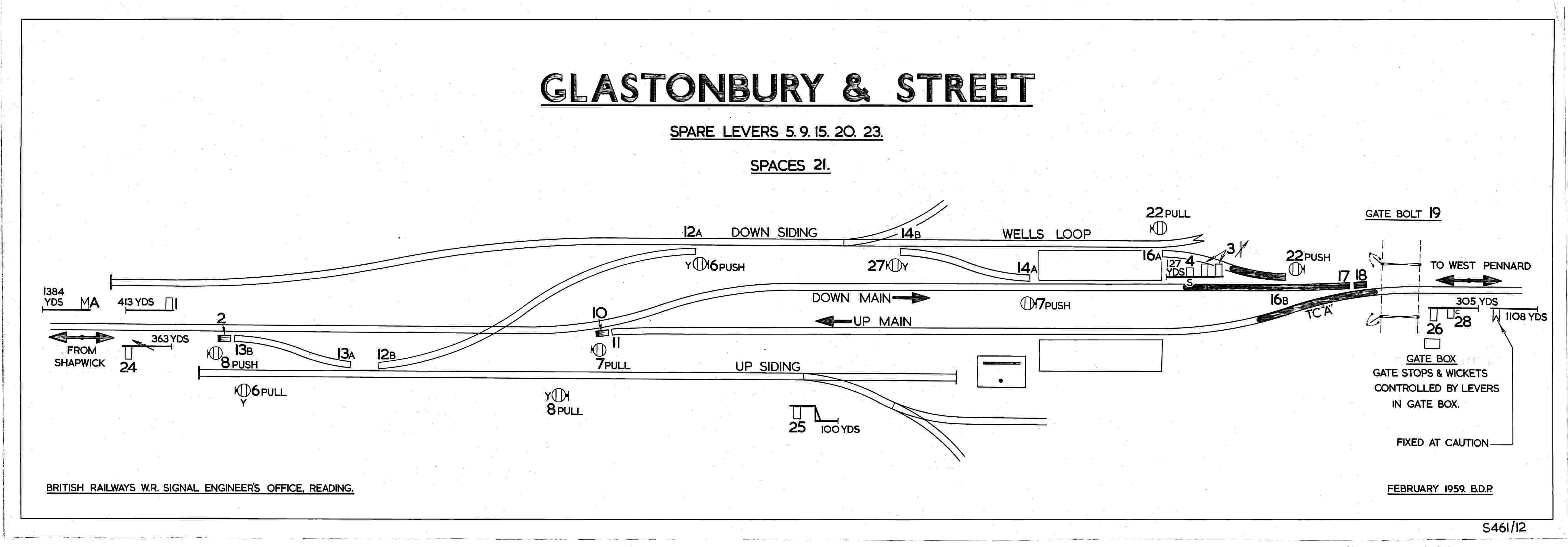 |
| Glastonbury Signal Diagram
circa-1963 Click diagram for larger image |
Apart from the main changes brought about by closure of the Wells Branch there had been some further alterations. In particular it should be noted that lever 3 has been converted to 'normal' working of the Up Starting signals only, with the subsidiary 'Shunt Ahead' arm now worked by lever 4. A track-circuit 'A' has been added at the eastern end of the loop and signal 27 has been converted to a 'yellow' ground signal (although no photographic evidence of that has come to light yet).
On 14-August-1964 the SB at West Pennard was closed and the single-line block section extended to Evercreech Jcn North. Glastonbury SB itself closed on 6-March-1966 along with most of the S&DJR, but the framed signal-box diagram passed into private hands and is now in the Museum of the Somerset & Dorset Railway Heritage Trust at Midsomer Norton station. That diagram would appear to be identical to the updated version seen above (even the abolition of West Pennard box has not been included), which would suggest that no further (significant) changes occurred to the signalling installation in its last few years.
At the time that the station and SB were closed in 1966 the Down Distant signal had an upper quadrant arm on a wooden post (click here to see a photograph). Given that SI 300 stated that the signal was relocated, as opposed to renewed or replaced, in 1929 then it is probable that the wooden post dated from an earlier installation, as it would seem unlikely that any post-1929 renewal would have been done with a wooden post. Allowing for the fact that many S&DJR signals have escaped the post-1948 photographic record, this signal would appear to have been the last known example of a wooden post signal on the S&DJR; it was also one of the few signals at Glastonbury to have been converted to an upper-quadrant arm (at an unknown date).
There are difficulties in establishing the limits of early S&DJR block sections, because of the practice of providing block telegraph instruments at intermediate stations. This problem affects research into Glastonbury also, because of the uncertain status of Ashcott in the early years. A decision was made at the S&DJR Officers’ meeting on 8-November-1876 (Minute 374) to provide a block switch at Ashcott, but unlike similar stations (eg Midford, Henstridge) at that time there is nothing about it in WTT Appendix No 7 dated 1-March-1886, which is the next available record.
An S&DJR letter dated 16-December-1878 states that block working at Glastonbury was by "train staff and ticket with Absolute Block", but this would appear to be a false claim as at that time the S&DJR was working its single-lines by block telegraph only. [National Archives file MT6/609/1, where the S&DJR’s entry in the 'Returns on systems of control as at 31-December-1885' under the Railway Regulation Act 1873 states "Burnham - Evercreech 23m 69c single...worked on the Absolute Block system (in addition to the Train Staff system on single line sections)", has a hand-written note appended saying "this appears to be an incorrect return, this Company do not use the Train Staff with their trains but only with their Banking Engines" and there is a subsequent S&DJR letter dated 12-April-1886 apologising for their inaccurate return.] However the use of Train Staff and Ticket (TS&T) working was specified as a requirement by the BoT when they wrote to the S&DJR on 19-December-1878 sanctioning the extension of the Wells branch by a separate line into Glastonbury, and so TS&T was implemented subsequently for the Glastonbury - Wells 'A' section (apparently with effect from 1-January-1879 according to an unsighted copy of SI 19). Then in 1886 S&DJR Officers Minute 3390 of 23rd September records that conversion to TS&T working had been completed on the rest of the branch from Evercreech Junction to Highbridge on 13th September; details are listed in WTT Appendix 8 dated 1-October-1886, where the sections either side of Glastonbury are shown as extending to Wells, West Pennard and Shapwick.
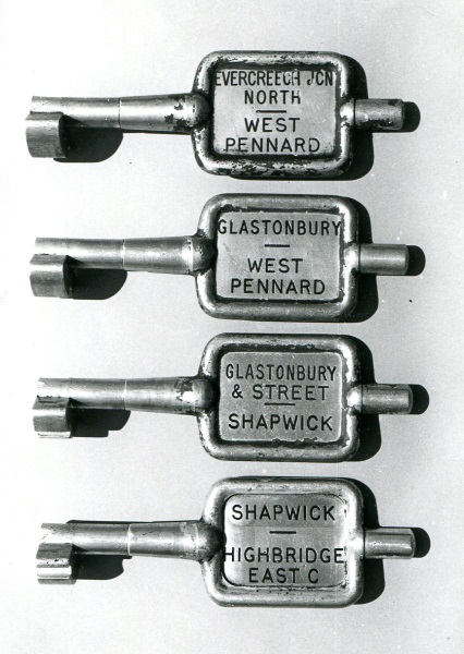 TS&T
working was replaced in due course by
Electric Train Tablet (ETT) working to West Pennard in 1888 (using
Tyers No 1 instruments), Shapwick in 1891 (Tyers No 3) and Wells 'A' in
1895 (Tyers No 1). About 1951-53 the ETT working on the
Evercreech
Junction to Highbridge branch was replaced by the BR(WR) pattern of
Electric Key Token (EKT), but the
Wells Branch is believed to have retained Tyers No 1 ETT until closure.
EKT working from Glastonbury to West Pennard was
introduced on 6-April-1952, using 'B' configuration tokens; EKT working
to Shapwick used 'C' configuration tokens, but the date
of introduction is unknown. This arrangement continued until the closure
of West Pennard SB on 14-August-1964, after which the section was
extended to became Evercreech Junction North - Glastonbury
(re-using the 'B' configuration tokens), and this revised situation
continued until the closure of the line on 6-March-1966.
TS&T
working was replaced in due course by
Electric Train Tablet (ETT) working to West Pennard in 1888 (using
Tyers No 1 instruments), Shapwick in 1891 (Tyers No 3) and Wells 'A' in
1895 (Tyers No 1). About 1951-53 the ETT working on the
Evercreech
Junction to Highbridge branch was replaced by the BR(WR) pattern of
Electric Key Token (EKT), but the
Wells Branch is believed to have retained Tyers No 1 ETT until closure.
EKT working from Glastonbury to West Pennard was
introduced on 6-April-1952, using 'B' configuration tokens; EKT working
to Shapwick used 'C' configuration tokens, but the date
of introduction is unknown. This arrangement continued until the closure
of West Pennard SB on 14-August-1964, after which the section was
extended to became Evercreech Junction North - Glastonbury
(re-using the 'B' configuration tokens), and this revised situation
continued until the closure of the line on 6-March-1966.
© CJL Osment 2004-24
Acknowledgements to the late David
Milton for access to his photographs, to Steve Erlicher and Peter Kay
for material from the National Archives, and to John Creed for details
from Signalling Record
Society archives.
Old signal-box photograph courtesy the late
Maurice Shaw, new signal-box interior and Up Home signal photographs ©
David Milton, Down Distant photograph © John Palmer, new signal-box exterior photograph
and track plan and WTT
Appendix extracts courtesy
S&DRT Archives,
telephone circuit 794 photograph courtesy
Great Central Railwayana
Auctions.
Other photographs from WCRA collection.
References
|
|||||||
| © West Country Railway Archives 2004 Page last updated: 21 February 2024 |
URL:
E-Mail: |
||||||


