


 |
Somerset &
Dorset Joint Railway Signalling at Wellow |
|
|||||||
|
|||||||||
The railway station and signal-box at Wellow were situated on the main line of the Somerset & Dorset Joint Railway (S&DJR), on the section from Bath Junction to Evercreech Junction in the county of Somerset which was known historically as the 'Bath Extension'. In 1874 the Somerset and Dorset Railway (S&DR) opened its 'Bath Extension' from Evercreech Junction to Bath and a station was provided at Wellow. At first the line was single-track throughout with a few passing-places and according to an undertaking given to the Board of Trade (BoT) by the S&DR on 15-July-1874 Wellow was the only block post between Bath Junction and Radstock. The S&DR became the S&DJR in 1875 when the line was leased jointly by the Midland Railway (MR) and London & South Western Railway (L&SWR).
With a steady increase in traffic various sections of the Bath Extension were doubled piecemeal until by 1894 the entire line had been doubled between Midford and Templecombe No 2 Junction. After the Grouping of the railways of Great Britain in 1923 the S&DJR became a Joint line under the control of the London, Midland & Scottish Railway (LMS) and the Southern Railway (SR), who were the successors to the MR and L&SWR respectively. When the railways were nationalised in 1948 the Joint line came under the control of British Railways (Southern Region) (BR(SR)), but in due course control of the old Bath Extension section passed to British Railways (Western Region) (BR(WR)) until the line closed on 6-March-1966.
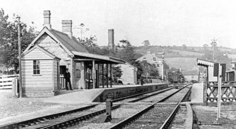
Looking up the line through Wellow station circa-1905
The original 1874 arrangement at Wellow is unknown, but some general information about early S&DR/S&DJR Signalling on the Bath Extension can be found here. Minute 27 of the S&DJR Officers’ meeting of 30-September-1875 (National Archives (TNA) file RAIL626/16) recorded a proposal to increase the length of the loop at Wellow to hold 30 wagons and engine and tender, so clearly there was a loop already in use by that date, but it is unclear whether two platforms existed at that time. By the time of the 1885 Ordnance Survey map (surveyed in 1884) the layout consisted of two platforms, a passing-loop and a trailing connection off the Up loop to a siding at the west (Radstock) end of the station.
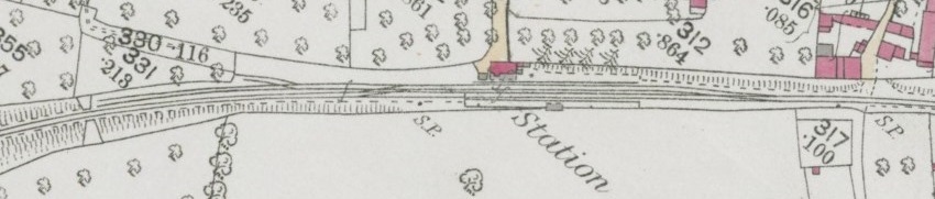
Map of Wellow station in 1884
Although the operating arrangements at Wellow were a factor in the S&DJR disaster at Foxcote (near Radstock) in August 1876, the evidence contained within the subsequent BoT Accident Report regrettably does not contain precise details about the signalling at Wellow, however there is some useful general information and it is clear that trains did pass at Wellow. Furthermore Henry Pullin, the Assistant Guard of the Down train involved in the Foxcote crash, stated in his evidence to the Inquiry that when his train stopped at Wellow "...the rear of the train was beyond the platform which was not long enough for the train...", so it may be presumed that a platform existed on the Down loop by that date. Although Wellow was supposed to be the first block post south of Bath, it is clear from the Accident Report evidence that Midford had been acting as some form of intermediate block post at that time, although it would appear that practice was terminated eventually.
Minute 363 of the S&DJR Officers' meeting on 8-November-1876 records a decision to enlarge the south end of Wellow signal-box (SB) at a cost of £50 and this was one of a series of such alterations along the line apparently to enable the block instruments to be relocated into the signal-boxes from the station buildings (probably as a consequence of the Foxcote disaster). When the Bath Extension was opened the block working on the single-line was by block telegraph without any physical train staff, but on 3-October-1886 Electric Train Tablet (ETT) working was introduced between Bath and Radstock using Tyer's No 1 instruments, the sections then being Bath Single Line Junction - Wellow - Radstock.
There are not many other specific references to Wellow signal-box in the available S&DJR records. In the Working Time Table (WTT) Appendix No 7 of 1-March-1886 it appears in the list of telegraph stations as code 'W' and is marked as being open always on weekdays and between 3pm and 4pm on Sundays. The same details appear in the 1-October-1886 WTT Appendix No 8, but by the No 9 issue of 1-February-1889 the Sunday opening had been amended to 'Midnight to Last Train, and 8.30pm to Midnight', and in the 1914 issue the Sunday telegraph times have been amended yet again to 'Midnight to Last Train, and 8pm or 10pm to Midnight'. No 'Local Instructions' for Wellow appear until the 1889 edition, which contained instructions (click here) relating to the need to inform Midford about trains entering the single-line section.
 Minute
3337 of the S&DJR Officers' meeting on 25-March-1886 recommended the
installation of a siding at Wellow to serve the new Fuller's Earth works being
constructed by Mr F Candy. This siding was located at the east (Bath) end of the station on the
Up side of the line, but it was accessed by a trailing connection off the Down loop and across the Up loop. The
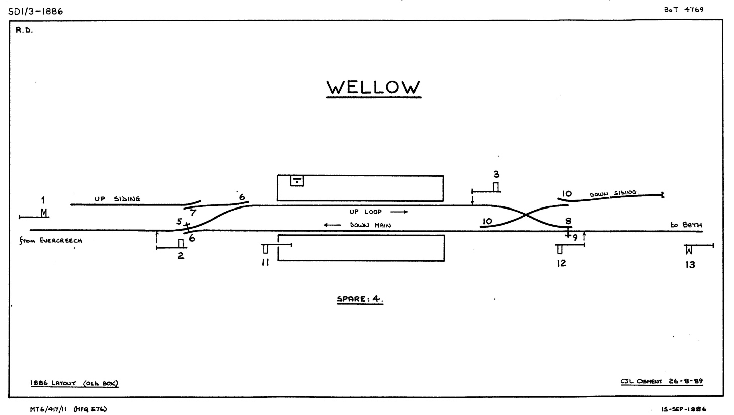
work was inspected for the BoT by Major Marindin and his Report dated 29-September-1886 (TNA file MT6/417/11) was accompanied by a track plan and a signalling
diagram (BoT4769 dated 15-September-1886). The diagram shown here (click for a larger
image) depicts the revised 1886 signalling arrangements with the Down
Siding and points 10 being the new work. It is clear that there was no provision at that time of any interlocking with any gates at the (unmarked)
level-crossing, which served a very minor track that crossed both the single-line and the new siding just on the Bath side of the Down Home (12).
Minute
3337 of the S&DJR Officers' meeting on 25-March-1886 recommended the
installation of a siding at Wellow to serve the new Fuller's Earth works being
constructed by Mr F Candy. This siding was located at the east (Bath) end of the station on the
Up side of the line, but it was accessed by a trailing connection off the Down loop and across the Up loop. The
work was inspected for the BoT by Major Marindin and his Report dated 29-September-1886 (TNA file MT6/417/11) was accompanied by a track plan and a signalling
diagram (BoT4769 dated 15-September-1886). The diagram shown here (click for a larger
image) depicts the revised 1886 signalling arrangements with the Down
Siding and points 10 being the new work. It is clear that there was no provision at that time of any interlocking with any gates at the (unmarked)
level-crossing, which served a very minor track that crossed both the single-line and the new siding just on the Bath side of the Down Home (12).
There were slight differences between the two BoT drawings, as the track plan marked the level-crossing at the Bath end of the station and specifically a 'signal box' on the platform, whereas the signal diagram omitted the former and labelled the latter merely as 'apparatus' - a term which, in some other locations, has suggested an uncovered lever-frame. However, on the basis of the evidence in the BoT Report on the 1876 Radstock Accident and other circumstantial details, it is probable that a covered structure did exist. It should be noted that, according to the information in the locking table attached to the original diagram, at that time there was no interlocking between the Starting and Distant signals (eg the Up Distant (1) was released solely by the Up Home (2)); see more on that subject here in the RailWest notes on early S&DJR signalling. Click here to see the relevant Local Instruction from the 1889 WTT Appendix regarding shunting operations at the new siding.
In 1892 the line from Midford to Wellow was doubled and new SBs were provided at both locations, the new work being opened on 28-August-1892 (S&DJR Signal Instruction 54). Two years later on 1-July-1894 double-track was opened from Wellow to Radstock (S&DJR Signal Instruction 69), with new SBs at Wellow, Writhlington and Radstock East (the existing Radstock SB became Radstock West). These works were inspected for the BoT and the Reports are contained in TNA files MT6/598/1 and MT6/669/14 respectively, but without any supporting signal diagrams. Both reports mention "new signal-boxes" of 18 levers and one report (but sadly the author's notes are unclear as to which one) referred to a "new Down platform"; as the earlier plan for the 1886 alterations already showed a Down platform, then 'new' presumably refers merely to some form of rebuild and/or extension. As the sections each side of Wellow were doubled the single-line ETT working was replaced by the standard S&DJR double-line 'block telegraph' on the new block sections Midford - Wellow - Writhlington - Radstock East - Radstock West.
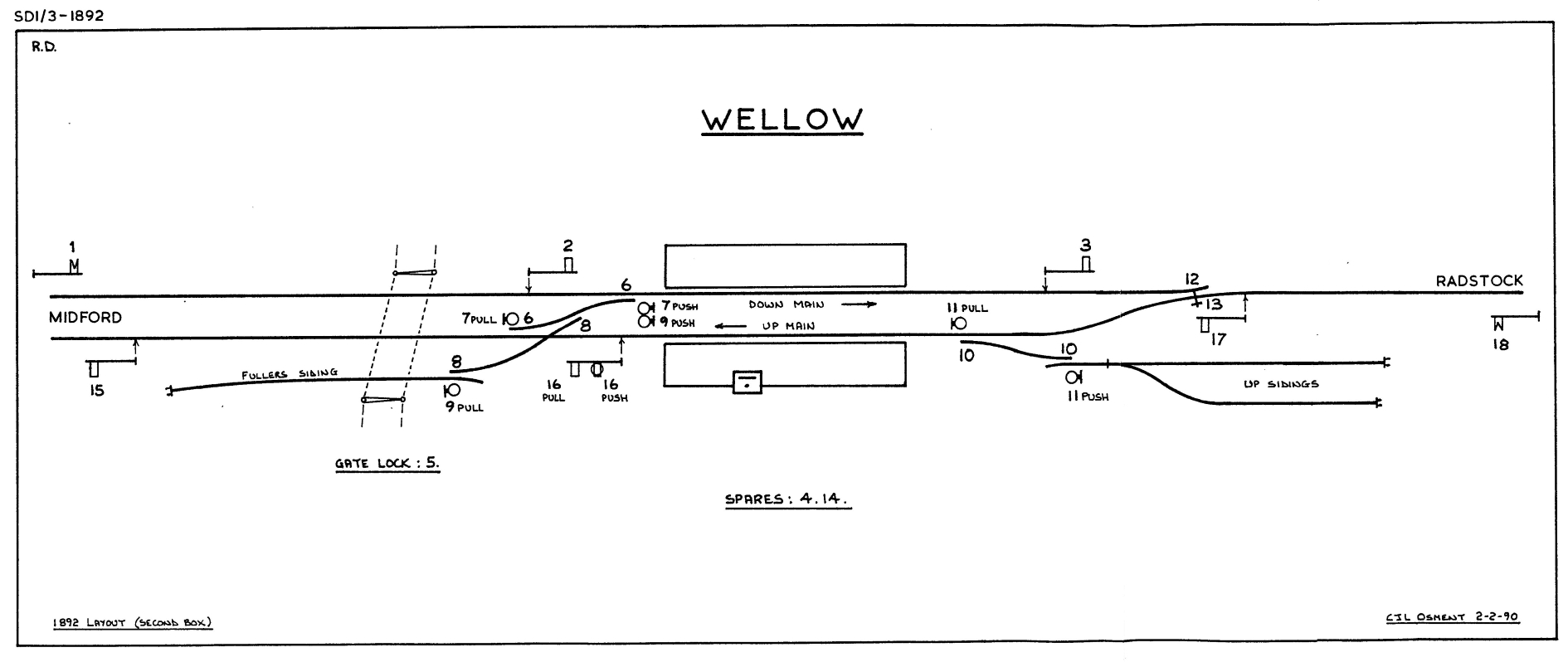
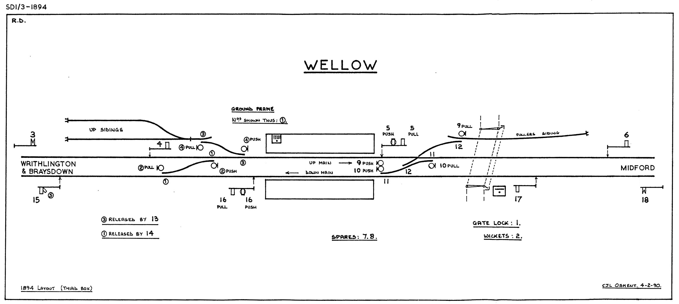
Some years ago a set of S&DJR signal diagrams which related to the various doublings of the Bath Extension during the early 1890s were unearthed in BR(WR) records and these included two drawings for Wellow. These diagrams were labelled as "Copy to the Secretary for the Board of Trade" and from the dates thereon they would appear to be relevant to the new works covered by the 1892 and 1894 BoT Inspection Reports. Drawings based on those diagrams are reproduced below and represent the 1892 and 1894 installations of the second and third SBs respectively at Wellow. It must be stressed that the origin of these diagrams separate from the TNA files does mean that there is no certainty that they represent the actual installations, as opposed to initial proposals, but on balance it is believed that they do indeed show the 1892 and 1894 arrangements.
 |
 |
|
| Wellow Signal Diagram 1892 Click diagram for larger image |
Wellow Signal Diagram 1894 Click diagram for larger image |
It may seem curious that the 1894 Inspection Report mentions a 'new' SB with 18 levers, as this might be considered too much of a coincidence just two years after a similar comment in the 1892 Inspection Report, but the source diagrams do seem to confirm this. Nevertheless it is surprising that a replacement box should be constructed after only two years for no obvious reason, particularly as the 1892 box was ideally situated to control the whole post-1894 layout, whereas the distance of the 1894 box from the Radstock end of the layout necessitated the provision of a separate ground-frame (GF) to control the pointwork at that end. Although there might have been a desire in 1894 to provide better supervision of the level-crossing from an adjacent SB, it should be noted that in the 1892 layout the Down Home (2) was not even in a position to protect the level-crossing from approaching Down trains anyway, yet it was interlocked with the Gate Bolt (5) (which locked the gates when the lever was reversed, contrary to later practice).
In view of the short life-span of the 1892 second SB it is not surprising that no photographic evidence of it has come to light yet, nor are any further details known about it. One can surmise that it would have been built in the same contemporary S&DJR TYPE 2 style as the new 1892 SB at Midford, so it is interesting to note that its position on the Up platform was approximately the same as that occupied later by a stone-built store which had barge-boards similar to Type 2 SBs. Some years ago a brief inspection was made of the inside of this building (which still exists in private ownership) and there were obvious signs of some sort of internal alterations and removal of possible equipment at some stage, so was that building actually the base of the 1892 SB rebuilt for a new use? The other tantalising fact about these new works is that the GF provided for the 1894 layout was located in approximately the same position as the first SB (compare the 1886 diagram); if one ignores the two-year period between the closure of the first SB and opening of the GF, then is it possible that the GF hut was in fact the original first SB structure or did the S&DJR merely take advantage of an existing pit in the platform ramp into which to locate the new frame?
The 1894 third SB was built to the same S&DJR TYPE 2 style as other contemporary SBs on the Bath Extension; it had a timber superstructure with vertical planking and distinctive 'wavy' barge-boards on a brick base. It contained an 18-lever frame of the Stevens 4.1/8" pattern with 'direct tappet' interlocking; the actual manufacturer is not known, but for that date it is likely to have been made by Stevens & Sons themselves. As will be seen from the 1894 diagram, the SB was located on the Down side of the line immediately on the Bath side of the level-crossing. More information about this SB can be found in the Signal-Box section below.
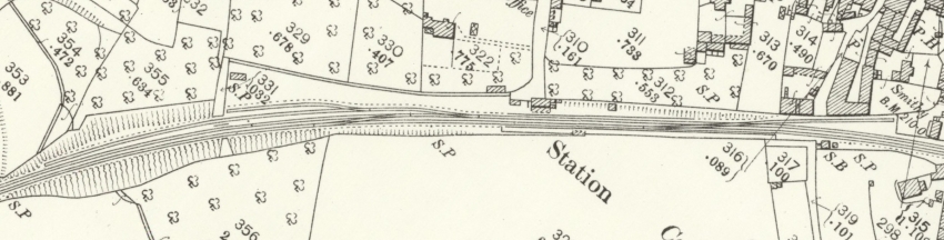
Map of Wellow station in 1902
 The photograph in the Introduction (click
here for a larger image) was taken about 1905 looking from the
Radstock end of Wellow station up the line towards Bath. Referring to the
1894 SB diagram, on the left at the end of the Up platform can be seen the
hut for the GF and in the foreground between the Up and Down lines can be seen the rear of the
GF's ground-signal 4PUSH which was of the L&SWR
'flap' type. The subsidiary 'Shunt By' arm 5PUSH and the L&SWR-pattern
'flap' ground-signals 9PUSH and 10PUSH can be seen in the background and it is clear that 5PUSH was a
ringed arm of
the usual S&DJR pattern, although the original diagram in fact depicted both
subsidiary 'Shunt By' arms 5PUSH and 16PUSH as 'diamond' arms in the L&SWR style.
The photograph in the Introduction (click
here for a larger image) was taken about 1905 looking from the
Radstock end of Wellow station up the line towards Bath. Referring to the
1894 SB diagram, on the left at the end of the Up platform can be seen the
hut for the GF and in the foreground between the Up and Down lines can be seen the rear of the
GF's ground-signal 4PUSH which was of the L&SWR
'flap' type. The subsidiary 'Shunt By' arm 5PUSH and the L&SWR-pattern
'flap' ground-signals 9PUSH and 10PUSH can be seen in the background and it is clear that 5PUSH was a
ringed arm of
the usual S&DJR pattern, although the original diagram in fact depicted both
subsidiary 'Shunt By' arms 5PUSH and 16PUSH as 'diamond' arms in the L&SWR style.
On 17-February-1907 (S&DJR Signal Instruction 189) the Up Home signal (4) was replaced on the same site by a right-hand bracket with an arm 23' above rail level. The Fuller's Earth siding was taken out of use by 1912, after which ground-signals 9PUSH and 9PULL and points 12 were removed. Both the subsidiary 'Shunt By' arms 5PUSH and 16PUSH were removed on 17-April-1913 (S&DJR Signal Instruction 237). On 29-March-1942 the Up Advanced Starting signal (6) was renewed at a height of 25' close to the existing signal (S&DJR Signal Instruction 389).
A train standing at the Up Starting signal fouled the clearance of crossover 11, so at some unknown date a mechanical fouling bar (believed to have been in two sections) was fitted to the Up line in rear of signal 5. This bar was worked by lever 7 and can be seen clearly in Plate 24 of Derek Phillips' 'Working Somerset and Dorset Steam' [1]. The bar was interlocked with lever 10, so that the crossover could not be reversed until the bar had been lifted to foul the flangeway of the Up line, which of course would not be possible if there was a train standing at the signal.
By 1930 the SB had been fitted with a closing-switch, but it is unclear whether the SB continued to be worked as a gate-box when switched-out or whether the low usage of the level-crossing meant that the gates remained locked across the road during such periods. The date of provision of this closing switch is unknown, although Wellow is not listed as a location so equipped as late as the 1919 Amendment to the 1914 WTT Appendix. The SBs at Writhlington and Radstock East had been provided already with closing switches by the time of the 1905 WTT Appendix, so there were occasions therefore when the block section extended from Midford all the way to Radstock West.
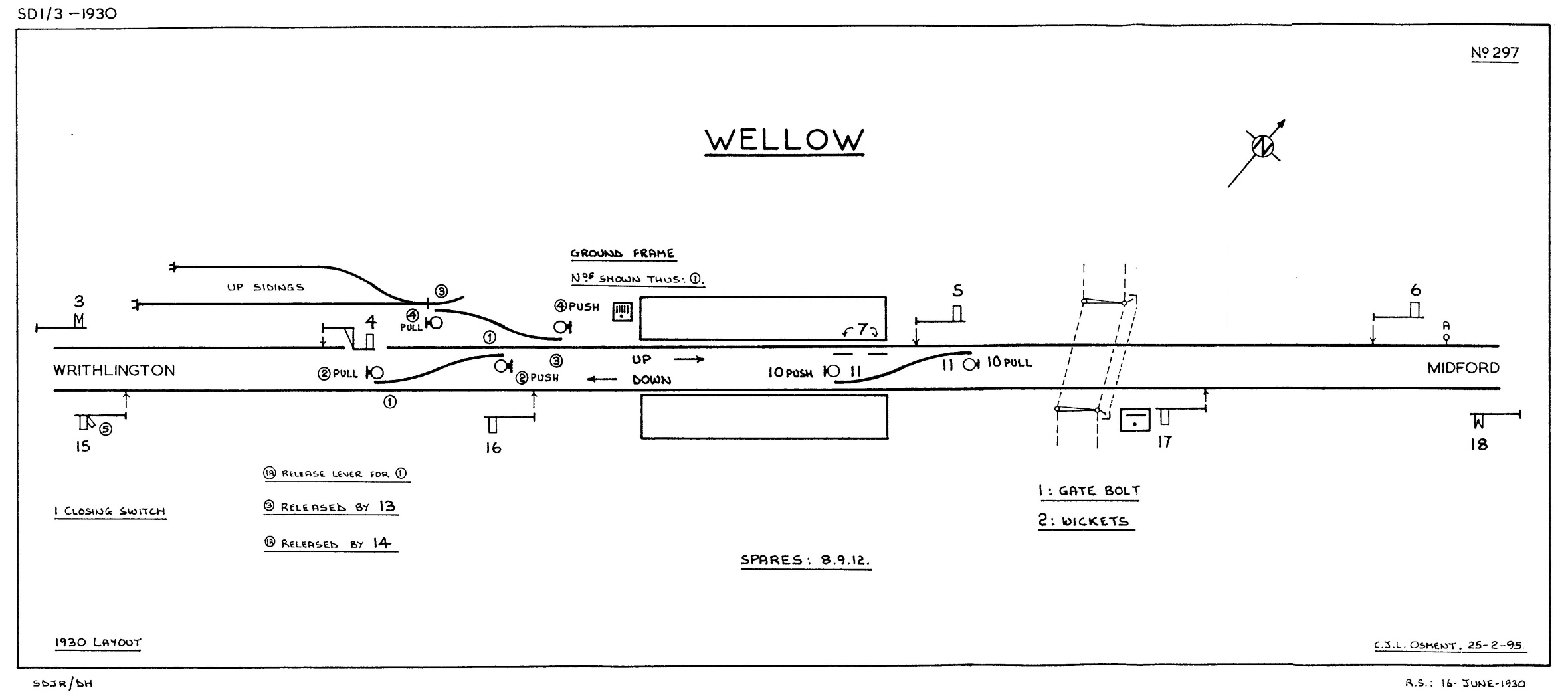
The next signal diagram which is available for Wellow from S&DJR records shows the signalling installation in 1930 (see below). By this date the GF had been extended by one lever, number '1A', the designation indicating that the lever had been added at the left-hand end of the frame (although the usual L&SWR/SR practice would have been to have labelled it simply 'A'). This new lever acted as an internal GF release lever for lever 1 (the crossover points) and consequently the release from lever 14 in the SB now acted on GF lever 1A rather than directly on lever 1. It is unclear why this addition was necessary when no similar provision was made for lever 3. However an un-referenced note from the Signal Engineer attached to the 1930 S&DJR diagram states that further changes to the GF would take place on 23-September-1945, when all the ground-signals worked from the GF were removed, as was the GF's slot on the Down Advanced Starting (15). As a result levers 2, 4 and 5 in the GF became spare. One source records that lever 2 was re-used to act as a release for lever 3 (in a similar way that lever 1A was used as a release for lever 1), but no evidence for this change is known and lever 2 was still listed as a spare in 1950.
 |
 |
|
| Wellow Signal Diagram 1930 Click diagram for larger image |
Wellow GF Locking 1950 Click diagram for larger image |
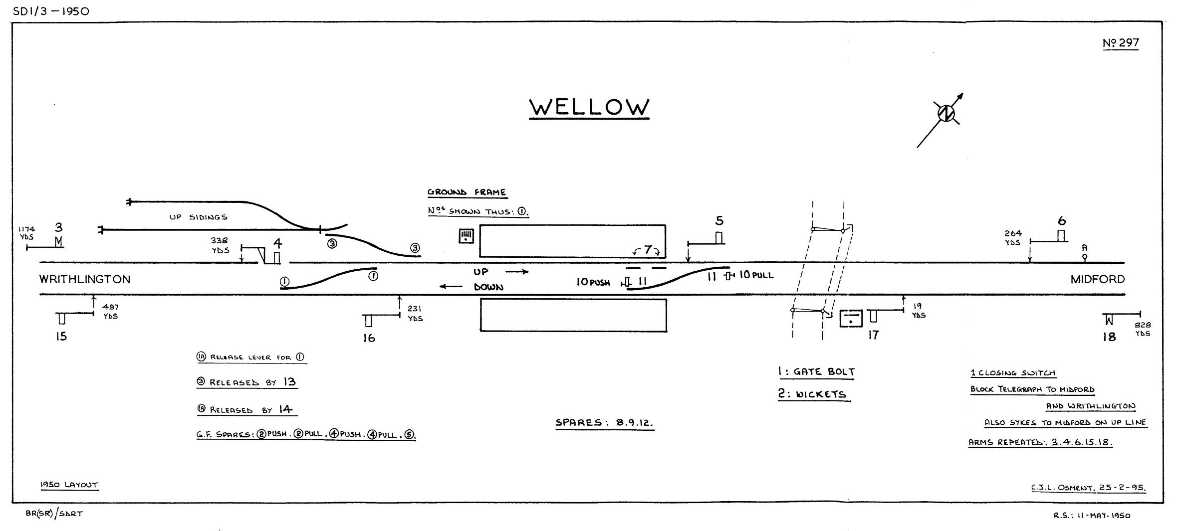
A BR(SR) signal diagram for the period circa-1950 (see below) shows that the signalling installation remained unchanged at that date. Also available are the Mechanical and Electrical locking-tables; although the copies date from the time of the 1945 alterations, it is believed that they should be compatible with the circa-1950 diagram. There are no known records of any further significant alterations during most of the BR period until the GF was taken out of use on 30-June-1964 (BR(SR) Weekly Notice P/EW24), together with the sidings and west crossover, at which date levers 13 and 14 became spares.
 |
 |
|
| Wellow Signal Diagram
circa-1950 Click diagram for larger image |
Wellow Locking Tables circa-1945 Click image for Mechanical and Electrical Tables |
Wellow SB was closed on 6-March-1966 along with the station and almost all of the S&DJR itself.
 It is a reasonable presumption that all the original
signals provided at Wellow had wooden
posts, but whether any of them survived the
1892 and 1894 alterations is unclear. Comparing with the work done at
Midford in 1892, then it is probable
that all the main running signals which existed after 1894 had wooden posts
also, although this can not be verified given the lack of suitable
photographic evidence. However by the 1950s no wooden posts survived, all
the main signals then being on either lattice posts or rail-built posts of
the S&DJR type. The Down Distant (18), Home (17) and Starting (16) signals
had the S&DJR-type rail-built posts, as also apparently did the Up Distant
(3) (but photo evidence is unclear); the Up Home (4) and Starting (5)
signals had lattice posts, as also apparently did the Up Advanced Starting
(6) (but again photo evidence is unclear). All those signals had plain
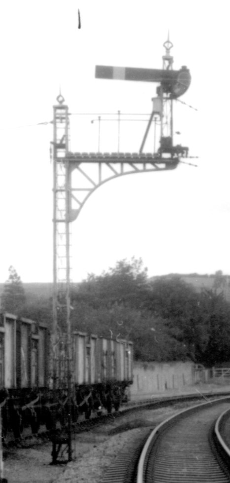
straight posts except for the Up Home, which became a right-hand bracket
when renewed in 1907 (click picture for larger image). At some unknown date the Up Starting and Up Advanced
Starting signals were converted to upper-quadrant arms (the latter probably being changed
when the signal was renewed in 1942), but all the other signals retained
lower-quadrant arms until the line closed in 1966. After 1894 the
ground-signals were of the L&SWR 'flap'
type, but by the BR period 10PUSH and 10PULL
had been replaced by the SR 'half-disc' type; there is photographic evidence
that at least one of the ground-signals worked from the GF was still of the
'flap-type' in 1936 and it is probable (but can not be verified) that all
four remained of the 'flap type' until they were abolished in 1945.
It is a reasonable presumption that all the original
signals provided at Wellow had wooden
posts, but whether any of them survived the
1892 and 1894 alterations is unclear. Comparing with the work done at
Midford in 1892, then it is probable
that all the main running signals which existed after 1894 had wooden posts
also, although this can not be verified given the lack of suitable
photographic evidence. However by the 1950s no wooden posts survived, all
the main signals then being on either lattice posts or rail-built posts of
the S&DJR type. The Down Distant (18), Home (17) and Starting (16) signals
had the S&DJR-type rail-built posts, as also apparently did the Up Distant
(3) (but photo evidence is unclear); the Up Home (4) and Starting (5)
signals had lattice posts, as also apparently did the Up Advanced Starting
(6) (but again photo evidence is unclear). All those signals had plain
straight posts except for the Up Home, which became a right-hand bracket
when renewed in 1907 (click picture for larger image). At some unknown date the Up Starting and Up Advanced
Starting signals were converted to upper-quadrant arms (the latter probably being changed
when the signal was renewed in 1942), but all the other signals retained
lower-quadrant arms until the line closed in 1966. After 1894 the
ground-signals were of the L&SWR 'flap'
type, but by the BR period 10PUSH and 10PULL
had been replaced by the SR 'half-disc' type; there is photographic evidence
that at least one of the ground-signals worked from the GF was still of the
'flap-type' in 1936 and it is probable (but can not be verified) that all
four remained of the 'flap type' until they were abolished in 1945.
In the 1933 WTT Appendix the Up Advanced Starting (6) was the sole entry in a Table of "Signals which are placed to danger automatically on the passing of trains". This suggests that this signal must have been fitted with one of the various forms of signal arm replacer, probably operated by treadle 'A', which released the signal arm back to the 'on' position automatically prior to the signalman restoring the relevant lever in the frame. (Curiously there is no mention of this automatic replacement facility on the 1930 SB diagram.) A footnote to the entry states that this applied only when the SB was open (ie 'in switch' as a block-post) - obviously the signal needed to stay 'off' while the box was closed. Supplement 4 to the 1933 Appendix (dated 7-May-1945) deletes the table entry; it is not known when the disengager equipment was removed, but presumably it was after the issue of Supplement 3 on 3-March-1937 and it may have been abolished when the Up Advanced Starting was renewed in 1942.
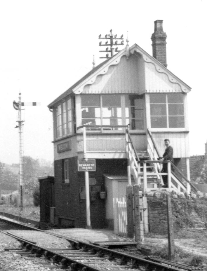
The 1894 (third) SB was built to the same S&DJR TYPE 2 style as other contemporary SBs on the Bath Extension; it had a timber superstructure with vertical planking on a brick base and a distinctive pattern of 'wavy' barge-boards on the gable ends of the roof. It contained an 18-lever frame of the Stevens 4.1/8" pattern with 'direct tappet' interlocking; the actual manufacturer is not known, but for that date it is likely to have been made by Stevens & Sons themselves.
| Wellow Signal Box in 1957 | Wellow Signal Box after closure | |||
 |
 |
 |
||
| Click photographs for larger images | ||||
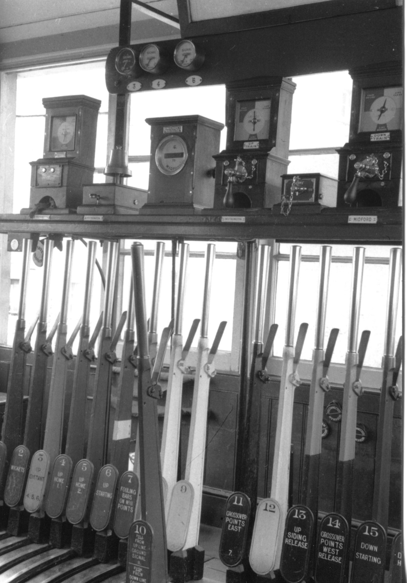
The photograph of the SB interior in 1957 shows standard S&DJR 'block telegraph' instruments together with a block bell and a closing-switch (similar to the GWR pattern) and some round brass 'arm repeaters' (SR type) for signals 3, 4 and 6. There would have been another block bell and instrument and two 'arm repeaters' for signals 15 and 18 mounted towards the right-hand end of the instrument shelf. Also visible is a Sykes 'indicator lock' instrument for the electric lock on lever 6 (the Up Advanced Starting signal), as the normal 'block telegraph' working to Midford was supplemented on the Up line only by the provision of a Sykes 'plunger lock' instrument at Midford. The lock on lever 6 was released when the signalman at Midford pressed the plunger on his Sykes instrument, after which the lever was back-locked until the departing train passed over treadle 'A'. The Sykes equipment was provided as a safeguard in connection with the requirement for occasional 'wrong road' working on the Up line at Midford; it was probably not an original fitting at Wellow as the treadle was not marked on the 1894 diagram and the associated 'wrong-road' signal at Midford was not part of the original 1892 installation there. It is unclear what happened when Wellow was switched-out as there is no evidence that the Sykes control was extended to the next box in circuit down the line, so it is possible that 'wrong-road' movements only took place at Midford when Wellow was switched-in.
One curious feature on the lever-frame in later years, which is visible in the 1957 interior photograph, is that the normal SR designations for the main running signals (eg Up Home, Up Starting, Up Advanced Starting etc) had been changed to the LMS nomenclature (Up Home 1, Up Home 2, Up Starting etc). There is an SR record that a complete set of 18 new lever description plates (using the LMS nomenclature) was ordered on 9-August-1945 and according to a pencilled note on the source copy of the 1930 signal diagram the alteration took place on 23-September-1945, but the reason is unknown. (One may speculate that perhaps the LMS was trying to exert its influence as the Operating Department on the Joint line?) There is evidence that similar changes in signal nomenclature took place at a few other S&DJR signal-boxes (eg Midsomer Norton) and may even have been reversed subsequently by BR(WR), but there is no further information about the situation at Wellow.
Postscript...
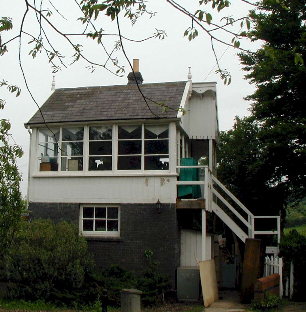 Wellow SB
and station were closed on 6-March-1966 along with
almost all of the S&DJR. Since that date the SB structure has remained standing and is
now in private ownership, albeit without its railway contents, and has been subject to
some restoration and alteration in recent years. It is now the only survivor of its type
and the only S&DJR SB structure to remain intact in its original location - the only in
situ relic to give something of the atmosphere of a S&DJR signal-box. Click
the picture for a larger image of the SB in 2006.
Wellow SB
and station were closed on 6-March-1966 along with
almost all of the S&DJR. Since that date the SB structure has remained standing and is
now in private ownership, albeit without its railway contents, and has been subject to
some restoration and alteration in recent years. It is now the only survivor of its type
and the only S&DJR SB structure to remain intact in its original location - the only in
situ relic to give something of the atmosphere of a S&DJR signal-box. Click
the picture for a larger image of the SB in 2006.
© CJL Osment 2006-22
Thanks to Steve Ehrlicher and Peter Kay for material from the National Archives
and Mike Arlett for additional information.
1884 and 1902 maps reproduced with permission of the
National Library of Scotland.
WTT Appendix extracts courtesy S&DRT
Archives, 1905 station photograph courtesy Wellow Archives, 1957 signal-box photographs
© Ian Scrimgeour courtesy Signalling
Record Society, other photographs and drawings from WCRA collection.
References
|
© West Country Railway Archives 2006 Page last updated: 07 July 2022 |
URL:
E-Mail: |
||||||


