 |
Somerset &
Dorset Joint Railway Double Line Block Working Equipment and Chronology |
|
||||||||
|
||||||||||
This page describes the various block control systems and instruments used on double-line sections of the Somerset and Dorset Joint Railway (S&DJR). There is a separate RailWest page specifically about block working on S&DJR single-line sections and also a page which provides a general Introduction to S&DJR Block Working. This page concentrates on providing basic information about the different types of double-line block equipment and their usage, and does not deal with the detailed methods of operation of the various instruments.
Initially the S&DJR was almost entirely a single-track line, with the exception of a few short sections of double-track working at locations such as Evercreech Junction or Templecombe Junction where there was more than one signal-box to control the layout. In 1884 the S&DJR started a programme of doubling many of its single-line sections, with the result that by the end of 1894 there was continuous double-track working all the way from Midford to Templecombe No 2 Junction; a further stretch from Blandford to Corfe Mullen Junction was completed between 1901 and 1905.
Information about block working on the double-line sections of the S&DJR is more limited than for single-line sections, as it was not dealt with in such detail in the various railway source documents, and details do not exist for all the block sections. Although photographs of the interiors of ex-S&DJR signal-boxes are quite common, there are very few pictures specifically of the various types of block instruments, so unfortunately the pictorial coverage of this subject in RailWest is rather limited.
The RailWest 'Introduction' page on the general history of S&DJR Block Working provides details about the original use of the 'absolute block telegraph' method of working for the single-line sections. It would appear that, as the various sections of the S&DJR main line were doubled, the existing 'block telegraph' equipment and regulations were applied to double-line use with very little alteration.
An extract from the S&DJR Working Time Table Appendix No 7
dated 1- March-1886
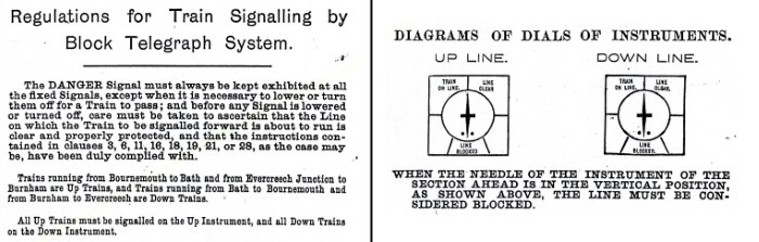
The S&DJR Block Regulations introduced in 1886 were still in use in 1889, but thereafter unfortunately there is a gap in available archive material until the 1905 Working Time Table (WTT) Appendix. By that time the bell codes had changed to more modern versions and the 'dial signals' appear no longer to form a integral part of block working, although they were still in use for some purposes. Even as late as 1914 the WTT Appendix contained the following Regulation:-
"3(f). Where Dial signals are used to indicate the direction in which a train requires to run, the direction from which a train is approaching or for any other purpose, they must, when used with the Is Line Clear? signal, be given immediately after that signal, and when used with the Train Entering Section signal, the Block Indicator, before being placed to Train On Line, must be placed in the normal position, and when the Dial signal has been given and correctly acknowledged, and the signal Signal correctly repeated (one beat of the Block Indicator to the Right) has been received, the Block Indicator must be placed to Train On Line".
By the 1920s the standard method of working S&DJR double-line sections was described simply as 'Block Telegraph'. Records of the London & South Western Railway (L&SWR) show that by the beginning of 1923 the block telegraph system was in use throughout the double-track sections of the S&DJR main line from Midford to Templecombe No 2 Junction and from Blandford to Corfe Mullen Junction. Unfortunately most evidence about the actual equipment dates from after nationalisation in 1948, but the basic principle appears to have been the use of 3-position instruments operated by a sprung drop-handle. The handle stood normally vertical, but could be held over to the left or right as required by a metal pin (or 'peg' - hence the references below to 'pegging') passed through the spindle to which the handle was attached. The pin was kept captive by a chain attached to the front of the instrument case.

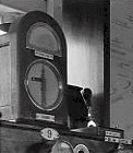
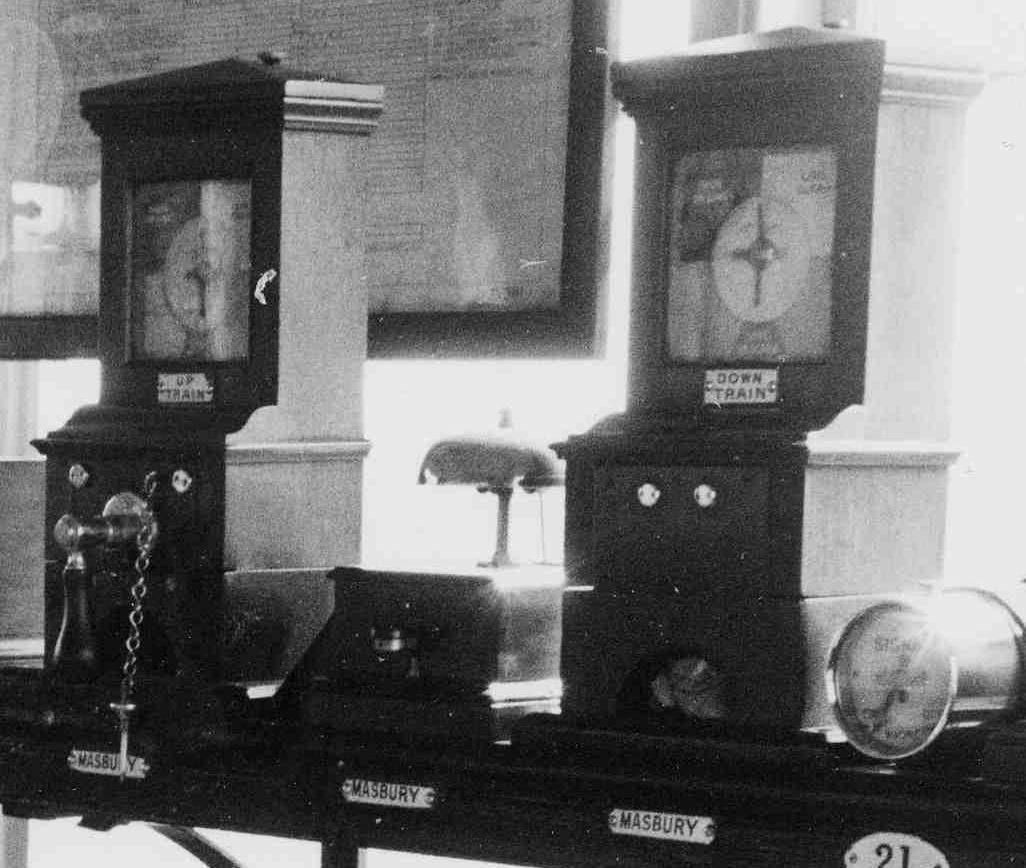 Each 'block instrument' in fact
consisted of two separate wooden cases containing the 'pegging' and 'non-pegging' portions; the cases were identical, but only the pegging portion had the drop-handle. The
colour picture on the left shows a typical 'pegging' S&DJR Block Telegraph instrument (on show at an exhibition),
the black&white picture on the right shows a 'pegging' (on the left) and
'non-pegging' (on the right) pair of instruments on the instrument shelf in
Binegar signal-box (for the section to
Masbury). Click either picture to see a larger image.
Each 'block instrument' in fact
consisted of two separate wooden cases containing the 'pegging' and 'non-pegging' portions; the cases were identical, but only the pegging portion had the drop-handle. The
colour picture on the left shows a typical 'pegging' S&DJR Block Telegraph instrument (on show at an exhibition),
the black&white picture on the right shows a 'pegging' (on the left) and
'non-pegging' (on the right) pair of instruments on the instrument shelf in
Binegar signal-box (for the section to
Masbury). Click either picture to see a larger image.
[Note: it appears that in earlier years the 'non-pegging' instruments also had drop-handles in order to allow the sending or acknowledging of 'dial signals', but these were removed in later years.]
The block telegraph instrument provided at Midford for working the block-section to Wellow varied from the normal arrangement (at least in British Railways days) in that a circular upper indicator (similar to those provided with the later Southern Railway block instruments) was fitted to top of the pegging instrument instead of the usual provision of a separate non-pegging instrument (click here to see a photograph of the interior of Midford signal-box). It is possible, but can not be proven, that this was a modification done at some unknown date in order to make space on the instrument shelf for additional equipment. No similar examples of this unusual arrangement are known anywhere else on the S&DJR.
The general appearance of the S&DJR Block Telegraph instrument was similar to the 'telegraph' used by many other railways including the Midland Railway (MR). Indeed the late JT Burge (a L&SWR stationmaster at Templecombe) made reference to the use of 'Midland Railway double-line' block on the S&DJR in his articles about the railway in some 1913/14 issues of the 'Railway and Travel Monthly' magazine. However at least some (if not all) S&DJR instruments differed from the MR pattern in that the handle was held over by a pin (on a chain) passed through the spindle (as seen in this picture), rather than by a MR-type 'trigger'.
At Bath Junction there would have been double-line working in force originally on the short section between the separate S&DJR and MR boxes (until both of these signal-boxes were replaced by a single new box in 1924), but no details are known. However, as the S&DJR box (Bath Single Line Junction) had been installed by the MR to their own design (but at the S&DJR's expense), then it is quite possible that the block equipment would have been MR pattern also.
Variations in block equipment occurred at the extremities of the system, where the S&DJR joined with other railways. In the Templecombe area Preece's 1-wire 2-position block was used on the two sections TEMPLECOMBE No 2 JUNCTION - TEMPLECOMBE 'B' - TEMPLECOMBE 'A' (later just a single section TEMPLECOMBE JUNCTION - TEMPLECOMBE) until the 1966 closure of the line. Preece's block equipment was used widely on the L&SWR itself, but it must have been somewhat alien to S&DJR signalmen, because the 1905 S&DJR WTT Appendix took no less than 8 pages to describe its operation yet said nothing about the standard S&DJR block telegraph! This photograph shows the Preece's instrument at Templecombe Junction signal-box in 1957 (click the picture for a larger image). To the right of the instrument can be seen the vertical 'switch handle' which formed the 'pegging' part of the equipment. |
|
At Wimborne Junction there was a short double-line section between the separate S&DJR and L&SWR signal-boxes (until the abolition of the S&DJR box in 1928) for which the working was described in the WTT Appendix merely as 'ordinary L&SWR electric block signalling instruments'. It is very likely that this was Preece equipment also, particularly as the L&SWR main lines in the Wimborne area used that system, but it is strange that it did not receive the same level of attention in the WTT Appendix as had been given to the Templecombe equipment. It is possible that perhaps it was the 3-wire version, which was a little simpler to operate, but this is doubted; certainly the L&SWR main line through Wimborne was listed as being worked by Preece 1-wire equipment in their records for 1911 and again in later Southern Railway (SR) records for 1923.
An interesting modification came into use at Binegar, Masbury, Winsor Hill and Shepton Mallet signal-boxes following the re-introduction of the Binegar bank staff in 1927. At each of these signal-boxes the block instrument working to the box up the line was replaced by a standard Southern Railway 3-position instrument (which had a rotary commutator operated by a round knob rather than a drop-handle), while the old S&DJR instrument was retained for working to the box down the line (eg at Masbury a new SR instrument was linked to an old-pattern S&DJR telegraph at Binegar while an old-pattern S&DJR telegraph was linked to a new SR instrument at Winsor Hill).
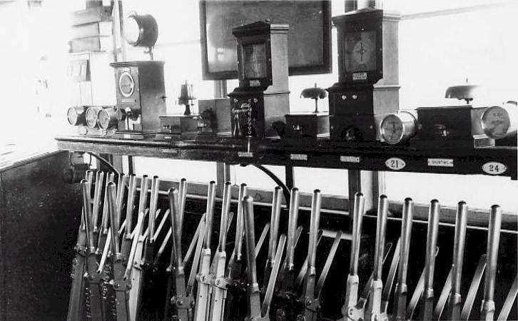
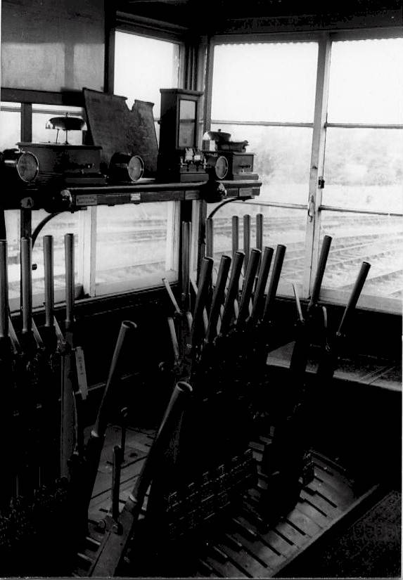
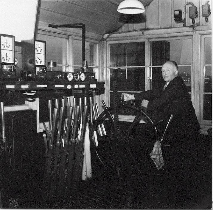
Block instruments in Binegar signal-box in 1965
This photograph shows part of the instrument shelf in Binegar signal-box in 1965 (click picture for a larger image of the signal-box interior). In the middle of the shelf is the 'pegging' instrument of the older S&DJR block telegraph controlling the Up line from Masbury, while on the right is the associated 'non-pegging' portion for the Down line to Masbury. Between those two instruments is the block bell for Masbury. On the left is the later SR block instrument working to Moorewood (the next box up the line); the indicator above the commutator knob is for the Down line from Moorewood, while the separate indicator on the top of the instrument is for the Up line to Moorewood. The Moorewood block bell is on the right of this instrument.
The Southern Railway block instruments were of a type where the commutator was prevented from turning to 'Line Clear' by an electro-magnetic lock released by a push-button on the instrument. At Masbury the push-button was wired to the commutator lock via lever 5 at Binegar (the bank staff release lever), to ensure that Masbury could not peg 'Line Clear' for a Down train if the bank staff was out of its lock at Binegar. When Masbury was closed the operation of its closing-switch extended this circuit through to Winsor Hill (and similarly through to Shepton Mallet when Winsor Hill was closed), so that in each case the release lock at the next box down the line from Binegar that was 'in switch' was controlled via lever 5 at Binegar. Fortunately Shepton Mallet was not fitted with a closing switch, or else this circuit might have stretched a long way done the line! It is strange that the SR left a mixture of equipment in use and did not replace all the instruments at once, but no doubt cost was a factor.
At Highbridge the S&DJR line to Burnham crossed the main line of the Great Western Railway (GWR) on the level and there was a connection between the two systems. Early block working arrangements at Highbridge are uncertain, but following the closure of Highbridge 'A' signal-box in 1914 double-line working was in force between Highbridge Loco (S&DJR) and Highbridge West (GWR) boxes. On this section the standard GWR Spagnoletti 'disc' block instruments were used, and those instruments certainly were still there in 1963. Those instruments were operated by two separate tapper keys, rather than by a rotary commutator, while the indications were given by twin flags which moved behind an aperture. Separate indicators for Up and Down lines were contained within the same case and it was GWR practice to paint the indicator face-plates white for 'Up' lines and green for 'Down' Lines. The photograph on the right shows the GWR Spagnoletti 'disc' block instrument inside Highbridge East 'C' signal-box (formerly known as Highbridge Loco) about 1963 (click the picture for a larger image of the signal-box interior). For a closer view of this type of instrument elsewhere on the S&DJR (although being used for a different purpose) click here for a picture of a similar Spagnoletti instrument in Highbridge East 'B' box in 1962. |
|
British Railways (Western Region) Block
In 1947 the Great Western Railway developed a new pattern of 3-position block instrument with a rotary commutator worked by a round knob in a similar way to the Southern Railway instruments. This type of block equipment was used extensively after nationalisation by British Railways (Western Region), including for some alterations on ex-S&DJR lines. The photograph on the right shows two GWR 1947-pattern commutator block instruments in Evercreech Junction South signal-box in 1966 (click picture for larger image). It is known from BR(WR) records that another pair of these instruments were in use at Evercreech Junction North signal-box at the same time. It is possible that in the final years of the S&DJR other block instruments of this type were introduced elsewhere as replacements, but there is no further information available at the present time. The S&DJR, SR, GWR and BR(WR) 3-position block instruments all worked to common principles over 3 wires (one each for the Up and Down indicators and 1 for the separate block bell), even if they appeared quite different externally. It was quite feasible therefore (with some minor adjustments to circuit resistance values etc) to work block sections with different styles of instruments at each end. |
|
The MIDFORD - WELLOW section was worked by the usual S&DJR block telegraph, but in addition a Sykes 'Plunger Lock' instrument was provided for the Up line only. The pegging handle of the 'block telegraph' instrument at Midford was fitted with an electric lock (operated by a push-button sunk into the front of the block instrument shelf) that prevented 'Line Clear' being given to Wellow until the signalman at Midford had plunged on the Sykes instrument. This arrangement was required because of the 'wrong-road' shunting movements that were permitted on the Up line at Midford - click here for more information about this aspect of the working at Midford. It is possible that Sykes equipment was used elsewhere for block working, but no examples have come to light and it is difficult to imagine any locations on the S&DJR where full Sykes 'Lock & Block' working would have been required.
It is known that Sykes 'Indicator Lock' instruments existed in connection with treadles and locks on the section signals at some S&DJR locations, such as the Up Starting signal (No 20) at Corfe Mullen Junction and the Up Advanced Starting signal (No 6) at Wellow (click here to see a photograph of the interior of Wellow signal-box). There were also some Sykes releases used to control various in-section ground-frames (eg Downside Siding) in earlier S&DJR days, but those were not connected with actual block-working. Click here for more general information about the use of various types of Sykes instruments on the S&DJR.
© CJL Osment 2002-26
Preece, Spagnoletti and Binegar instrument photographs © Ian Scrimgeour courtesy Signalling Record Society,
all other images WCRA collection.
References
| © West Country Railway Archives 2004 Page last updated: 27 January 2026 |
URL:
E-Mail: |
||||||