


 |
Somerset &
Dorset Joint Railway Signalling at Midsomer Norton |
|
|||||||
|
|||||||||
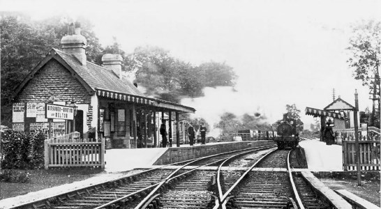
The railway station and signal-box at Midsomer Norton were situated on the main line of the Somerset & Dorset Joint Railway (S&DJR), on the section from Bath Junction to Evercreech Junction in the county of Somerset which was known historically as the 'Bath Extension'.
 |
 |
|
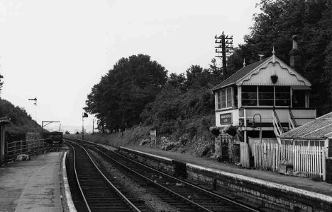
| Looking down the line through Midsomer Norton station in the early 1900s (left) and in 1963 (right) | ||
In 1874 the Somerset and Dorset Railway (S&DR) opened its 'Bath Extension' from Evercreech Junction to Bath and a station was provided at Midsomer Norton. At first the line was single-track throughout with a few passing-places, one of which was at Midsomer Norton according to an undertaking given to the Board of Trade (BoT) by the S&DR on 15-July-1874. The S&DR became the S&DJR in 1875 when the line was leased jointly by the Midland Railway (MR) and London & South Western Railway (L&SWR). Click here to read more about early S&DR/S&DJR Signalling and the nature of the original signalling and layout arrangements on the Bath Extension.
With a steady increase in traffic various sections of the Bath Extension were doubled piecemeal, until by 1894 the entire line had been doubled between Midford and Templecombe No 2 Junction. After the Grouping of the railways of Great Britain in 1923 the S&DJR became a Joint line under the control of the London, Midland & Scottish Railway (LMS) and the Southern Railway (SR), who were the successors to the MR and L&SWR respectively. When the railways were nationalised in 1948 the Joint line came under the control of British Railways (Southern Region) (BR(SR)), but in due course control of the old Bath Extension section passed to British Railways (Western Region) (BR(WR)) until the line closed on 6-March-1966.
A note on naming: When the station was opened in 1874 it was named simply 'Midsomer Norton', but it was re-named 'Midsomer Norton & Welton' on 16-October-1898. (It is unclear what happened officially to the name of the signal-box itself, but it appears that it may have remained unchanged.) On 26-September-1949 both the station and signal-box were re-named 'Midsomer Norton Upper', but a year later on 25-September-1950 they were re-named again as 'Midsomer Norton South'. For consistency the simple form 'Midsomer Norton' has been used throughout in RailWest, except where circumstances require a more precise description.
When the Bath Extension was opened in 1874 the station at Midsomer Norton was one of the original passing-loops on the line. The railway passed through the station on roughly a north-east to south-west alignment, the direction of travel being defined as 'Up' to Bath and 'Down' to Evercreech Junction. To the north the next passing-loop was at Radstock, whilst southwards the next passing-loop initially was at Binegar, but in 1876 a further passing-loop was opened at Chilcompton. It is unclear exactly what the original layout was at Midsomer Norton, but with reference to a later Ordnance Survey map and a comparison with the arrangements at Wellow, it is likely to have comprised a basic passing-loop with a siding connection into the goods yard on the Down side. (The OS map appears to show more than one trailing connection off the Down loop into the sidings.) The points and signals would have been worked from a lever-frame probably located in a small wooden hut somewhere on the down platform close to the station building. The actual provision of signals probably was limited to Distant, Home and Starting signals in each direction, and it is reasonable to assume that these would have had lower-quadrant (LQ) arms on wooden posts, consistent with the contemporary style.
Minute 27 for the S&DJR Officers' meeting on 1-October-1875 recorded a decision for the passing-loop at Midsomer Norton, in common with some other stations on the Bath Extension, to be extended "...to 30 wagons plus engine and tender". In the following year at an Officer's meeting on 8-November-1876 Minute 365 recorded that "The extension of the loop....is to be carried out as early as may be convenient. Estimated cost £250", so it is assumed that this work was done in due course. Minute 27 had stated also "Siding for 20 wagons to be provided with points into the up main line", but given the absence in later years of any up siding it is unclear if such a siding was ever provided.
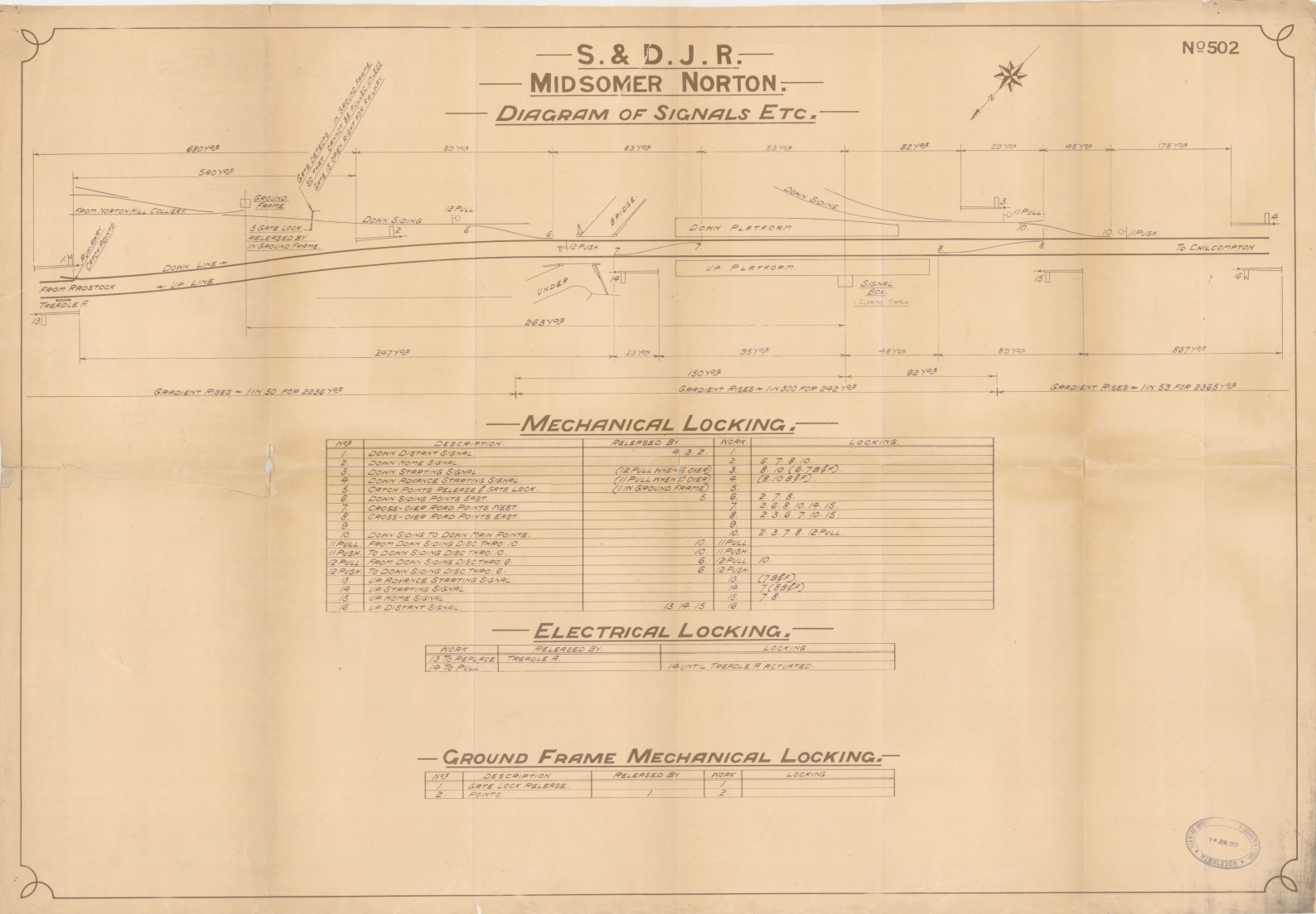
In 1886 the line from Radstock through Midsomer Norton to Chilcompton was converted to double-track and the work was inspected for the Board of Trade (BoT) by Colonel Rich; both his Inspection Report of 14-April-1886 and a subsequent Report dated 8-June-1886 for a further re-inspection can be found in National Archives file MT6/409/1. (The initial report covered Radstock, Midsomer Norton and Chilcompton, but it is not clear if he re-visited Midsomer Norton in June.) In connection with this work the original signal-box at Midsomer Norton was closed and a new signal-box (SB) was built on the Up platform; this was constructed to the S&DJR TYPE 2 style and contained a 16-lever interlocking frame. Sadly there are no known records to show exactly what the initial 1886 installation looked like, but it probably consisted of the double-track with a crossover at each end of the platforms and a single siding connection into the goods yard on the down side at the Chilcompton end of the station. It is likely that Distant, Home, Starting and Advanced Starting signals were provided in each direction. There is some evidence to suggest that no ground signals were provided initially; certainly that was the case with the new SB which was opened at Chilcompton at the same time.
After the line was doubled a spring-loaded trailing catch-point was provided on the Down line between the Down Distant and Down Home signals. This catch-point guarded against any runaways, whether from un-banked Down goods trains or shunting operations at Midsomer Norton, running 'wrong direction' back along the Down line on the steep gradient down towards Radstock. It is not known if this was installed in 1886 concurrent with the doubling, but certainly it was listed in the 1905 S&DJR Working Time Table (WTT) Appendix which stated that "the position is indicated by the word 'Switch' painted in black letters on the small Signal-box covering the handle of the Catch Points". (That 'signal-box' would have been little more than a small hut.) In 1906 the catch-point was recorded as being 390 yards in rear of the Down Home, but by the time of the 1933 edition of the WTT Appendix it had been moved further out to 540 yards from the Down Home in order to provide clearance for the longer goods trains that became possible after the introduction of the 2-8-0 '7F' engines (see Minute 7786 of the S&D Officers' Conference on 23-April-1926). At some unknown date the 'box' was removed and replaced by a small 'CATCH POINTS' notice on a post close to the catch-point lever.
[Note: by 1907 the crossovers at the Radstock and Chilcompton ends of the station were designated as 'West' and 'East' respectively, despite the fact that geographically the former was east of the latter, yet the new siding to the Colliery was designated Down Siding East and later the goods yard siding became Down Siding West. This anomaly was corrected in 1945 when new lever description plates were ordered for the signal-box and the crossovers at the Radstock and Chilcompton ends were re-designated 'East' and 'West' respectively.]
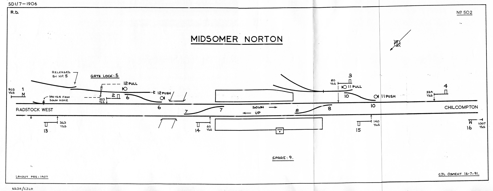
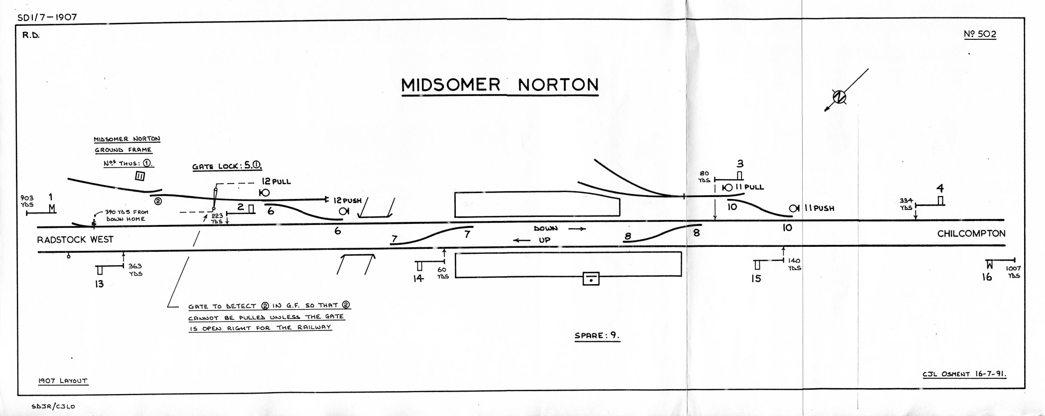
Colliery siding. On 25-July-1900 a new siding connection was brought into use to serve the nearby Norton Hill Colliery. This siding trailed into the Down line on the Radstock side of bridge 48, which carried the railway over Silver Street next to the Radstock end of the station. The work was inspected by the BoT in July 1900 and the Inspection Report can be found in National Archives file MT6/977/6. Sadly it does not contain any detailed layout information, but by late 1906 the signalling arrangements were as shown in the left-hand diagram below (from information in S&DJR records). Click here to see the detailed instructions for the working of the colliery siding, which were published in the 1905 S&DJR WTT Appendix.
 |
 |
|
| Midsomer Norton Signal Diagram circa-1906 Click diagram for larger image |
Midsomer Norton Signal Diagram 1907 Click diagram for larger image |
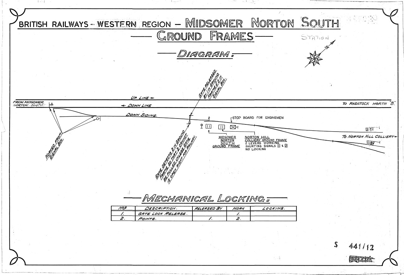
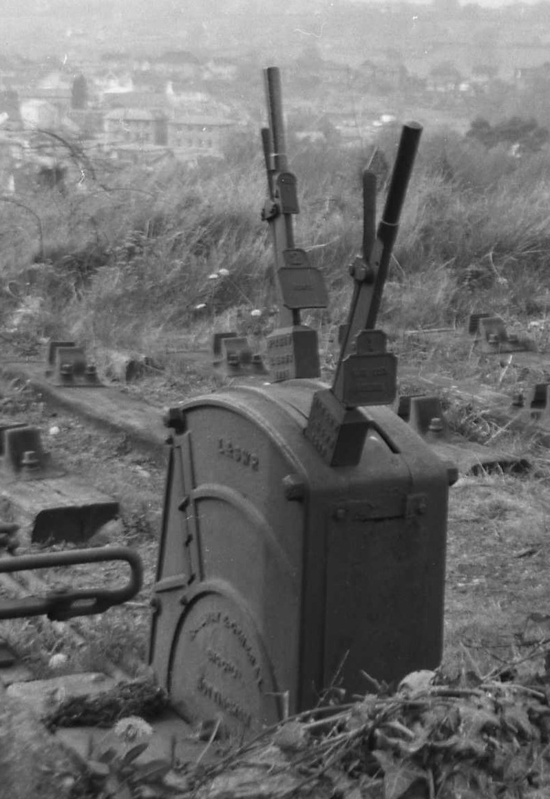 Ground
Frame. S&DJR Signal Instruction No 160 advised that
on 21-March-1907 a new 2-lever ground-frame (GF) would be provided on the
Colliery siding, as shown in the right-hand diagram above. This GF was a typical
L&SWR 'knee' frame of the Stevens pattern, but photographic evidence
suggests that
it was manufactured by the Railway & General Engineering Co Ltd of Nottingham
(click photo for a larger image).
Lever 1 in this GF released the Gate Lock lever 5 in the SB, while lever 2
worked the trap-point previously worked by a hand-lever. It would appear from photographic evidence in the BR era
that the rod run from SB lever 5 passed through the lock
mechanism below the gate handle and extended alongside the siding to a
release lock next to the GF; the latter ensured that the rodding from SB
lever 5 could not be moved to unlock the gate until GF lever 1 had been
reversed. In addition some form of mechanical
'detection' was provided at the hinged end of the gate to ensure that GF lever 2 could not be reversed until
the gate had been moved to its open position.
Ground
Frame. S&DJR Signal Instruction No 160 advised that
on 21-March-1907 a new 2-lever ground-frame (GF) would be provided on the
Colliery siding, as shown in the right-hand diagram above. This GF was a typical
L&SWR 'knee' frame of the Stevens pattern, but photographic evidence
suggests that
it was manufactured by the Railway & General Engineering Co Ltd of Nottingham
(click photo for a larger image).
Lever 1 in this GF released the Gate Lock lever 5 in the SB, while lever 2
worked the trap-point previously worked by a hand-lever. It would appear from photographic evidence in the BR era
that the rod run from SB lever 5 passed through the lock
mechanism below the gate handle and extended alongside the siding to a
release lock next to the GF; the latter ensured that the rodding from SB
lever 5 could not be moved to unlock the gate until GF lever 1 had been
reversed. In addition some form of mechanical
'detection' was provided at the hinged end of the gate to ensure that GF lever 2 could not be reversed until
the gate had been moved to its open position.
[Note: The wording on the GF end-plate is believed to read 'RAILWAY & GENERAL Eng Co Ltd NOTTINGHAM'. However the top line of the wording on the side of the catch-blocks appears to read 'McK & H W' (for McKenzie & Holland, Worcester.) It is possible therefore that the S&DJR constructed the lever-frame from an assortment of spare parts from their stores; alternatively it may be that the frame was supplied by RG&E originally, but the catch-blocks were replaced at a later date because of damage or wear.]
After the opening of the colliery siding in 1900, there would appear to have been no further substantial change to the overall layout at Midsomer Norton for the remaining life of the station. The 1900 Inspection Report did include a reference to the fact that "discs have been ordered but not yet supplied for 10" (the existing points for the goods yard), which would seem to confirm that the original installation of 1886 had no ground signals. It is probable, but can not proven in the absence of any relevant correspondence, that ground signals were provided for the new siding in accordance with contemporary practice and the BoT may have requested that the existing siding be equipped at the same time. However it should be noted that subsequently SI 216 advised that a 'new semaphore ground signal' would be provided in the 'six foot' on 17-June-1910 to control movements from the Down Main into the colliery siding (effectively signal 12PUSH in the diagrams above). It is not clear whether this was simply a relocation of an existing ground signal from outside the Down line into the 'six foot', a replacement of a signal already in that location, or in fact the first provision of a signal at that point, in which case had the 1900 work actually included any ground signals for that siding?
There are no Signal Instructions known for Midsomer Norton after No 216 and any later alterations have been identified (or deduced) only from other records. The signal diagrams shown below for 1930 and 1949 are almost identical to that for 1907. By 1949 the Down Advanced Starting (4) had been moved to the right-hand side of the line, probably to improve sighting of it by Down trains on the left-hand curve heading towards Chilcompton; the relocation date is unknown, but it may have occurred when the signal was renewed in 1933. The Down Starting (3) stood in an elevated position on the hillside above the high retaining wall adjacent to the Down Siding.
 |
 |
|
| Midsomer Norton Signal Diagram 1930 Click diagram for larger image |
Midsomer Norton Signal Diagram 1949 Click diagram for larger image |
Treadle. It will seen on the preceding diagrams that there used to be a Treadle 'A' on the Up line about 100 yards in advance of the Up Advanced Starting (13); there was a proposal in 1950 to replace this treadle with a short track-circuit at the same location, but it would appear that this change did not take place. Instead at an unknown date (but probably circa-1950/51) the treadle was abolished and replaced by a longer track-circuit (designated '14T' by BR(WR)) which extended along the Up line from just clear of points 7 as far as signal 13. It is assumed that it was as a result of that change that a diamond sign was provided on signal 13 in BR days. The new arrangements can be seen in the signal diagram below for the 1960s period.
[Note: Childs [1] states that treadle 'A' was a 'Last Vehicle Treadle' (LVT), but there is no known evidence to support that claim. Usually a LVT was marked as such on the signal diagram (as was the case at Midford), nor was the use of a LVT applicable to the situation at Midsomer Norton.]
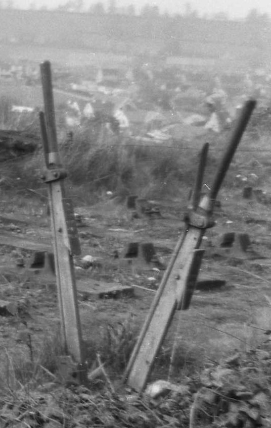 Norton
Hill Colliery GF. In October 1952 a second 2-lever GF was installed a few yards east of the
existing GF (click photo for a larger image). The new GF appears to have
been a standard BR(WR) pattern and it did not replace the
existing GF, which remained in use. It controlled elevated shunt signals
(facing to outgoing traffic) on the
two sets of colliery sidings which converged just east of the GF; lever 2 controlled the signal
on the colliery line nearest to the main line and lever 1 controlled the
signal on the next adjacent colliery line. These signals were not
interlocked with each other, nor with anything else in the installation. By
1966 these signals were standard BR(SR) 'half-disc' ground signals, elevated
by about 2 to 3 feet on short lattice posts, but it is unclear how BR(SR) signals
came to fitted at a location installed with a BR(WR) lever-frame
under BR(WR) auspices. A 'stop board' was erected on the south side of the
siding just east of the two GFs, facing to outgoing traffic, and this was
worded "ENGINES
MUST NOT PASS THIS BOARD WITHOUT PERMISSION OF RAILWAY SHUNTER".
The new arrangements can be seen in the signal diagrams below for the 1960s
period.
Norton
Hill Colliery GF. In October 1952 a second 2-lever GF was installed a few yards east of the
existing GF (click photo for a larger image). The new GF appears to have
been a standard BR(WR) pattern and it did not replace the
existing GF, which remained in use. It controlled elevated shunt signals
(facing to outgoing traffic) on the
two sets of colliery sidings which converged just east of the GF; lever 2 controlled the signal
on the colliery line nearest to the main line and lever 1 controlled the
signal on the next adjacent colliery line. These signals were not
interlocked with each other, nor with anything else in the installation. By
1966 these signals were standard BR(SR) 'half-disc' ground signals, elevated
by about 2 to 3 feet on short lattice posts, but it is unclear how BR(SR) signals
came to fitted at a location installed with a BR(WR) lever-frame
under BR(WR) auspices. A 'stop board' was erected on the south side of the
siding just east of the two GFs, facing to outgoing traffic, and this was
worded "ENGINES
MUST NOT PASS THIS BOARD WITHOUT PERMISSION OF RAILWAY SHUNTER".
The new arrangements can be seen in the signal diagrams below for the 1960s
period.
 |
 |
|
| Midsomer Norton South Signal Diagram circa-1960s Click diagram for larger image |
Midsomer Norton South Ground-Frames Diagram circa-1960s Click diagram for larger image |
Although surviving official diagrams for the SB and GF from the 1930s onwards depict the gate with the lock at its north end and hence hinged at its south end, photographic evidence from the BR period shows quite clearly the reverse arrangement, namely the lock at the south end and the hinges at the north end. It is unclear whether this apparent discrepancy is the result of an alteration at some unknown date, or merely the fact that the precise arrangement was not known to the original draughtsman. The gate swung open in an anti-clockwise direction to rest between the siding and the main line pointing towards the Colliery.
On the diagram in the SB the original GF used to be marked simply as 'Ground Frame', but that was the normal practice when there was only one GF at an installation. It is possible that officially it was called 'Midsomer Norton & Welton GF' originally, or some other variation of the station or SB name. Certainly there are examples of the GF diagram from BR days which are labelled as 'Midsomer Norton Upper GF' or 'Midsomer Norton South GF' depending upon the date. The second GF added in 1952 was called 'Norton Hill Colliery GF'. It is doubtful whether either GF ever had an actual nameplate.
[Note: There is a large, cast-iron nameplate 'MIDSOMER NORTON & WELTON NORTH GROUND FRAME' in the Museum of the Somerset & Dorset Railway Trust and an equivalent '...SOUTH...' nameplate in a private collection. Those plates have no S&DJR connection, as they came from the former Great Western Railway station on the other side of the town.]
At some unknown date the main-line end of points 6 were fitted with a 'swing wing crossing', a sprung mechanism that closed the gap which normally exists at a crossing nose in order to provide a continuous rail surface for the main route. It is not known if any other points at Midsomer Norton were equipped in the same way.
 Over the years the actual signals provided at Midsomer Norton varied just as much as elsewhere on the
S&DJR. It is reasonable to assume that any new signals provided at
the time of the doubling of the line would have had LQ arms on wooden posts, but
all of these were replaced at various dates (maybe more than once).
For example, photographic evidence shows that the Up Starting (14)
was changed at some unknown date to a S&DJR-type rail-built post and then
again to a lattice post, but still with a LQ arm, before being converted to
an UQ arm on 15-April-1951. The Down Advanced Starting (4) was renewed in 1931
(quoted variously as 22nd January or 5th March), apparently as a SR-type rail-built post but still with a LQ
arm, and it may have been at that time that it was moved to the
right-hand side of the line. The Down Distant (1) was renewed on
18-March-1945 and it was probably at that time that it became a SR-style
rail-built post with an UQ arm.
Over the years the actual signals provided at Midsomer Norton varied just as much as elsewhere on the
S&DJR. It is reasonable to assume that any new signals provided at
the time of the doubling of the line would have had LQ arms on wooden posts, but
all of these were replaced at various dates (maybe more than once).
For example, photographic evidence shows that the Up Starting (14)
was changed at some unknown date to a S&DJR-type rail-built post and then
again to a lattice post, but still with a LQ arm, before being converted to
an UQ arm on 15-April-1951. The Down Advanced Starting (4) was renewed in 1931
(quoted variously as 22nd January or 5th March), apparently as a SR-type rail-built post but still with a LQ
arm, and it may have been at that time that it was moved to the
right-hand side of the line. The Down Distant (1) was renewed on
18-March-1945 and it was probably at that time that it became a SR-style
rail-built post with an UQ arm.
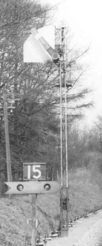
In BR days signal 13 was on a SR-type rail-built post and it is believed (but can not be confirmed) that 16 also had a post of that type; signals 2,3,14 and 15 were all on lattice posts. Signal 4 still had a LQ arm (see the right-hand image), but all the others were UQ. The Down Home (2) had a vertical sighting board fixed on the front of the lower three-quarters of the post, and a quadrant-shaped sighting plate had been fitted behind the arm of the Up Home (15) in January 1952 (see the left-hand image). There is a 1949 photograph of a L&SWR/S&DJR-style semaphore signal with a LQ arm on a lattice post within the colliery sidings, but it is believed that this had no connection with the S&DJR and was purely for internal colliery purposes.
[Note: Childs [1] states that both distant signals (1 and 16) had rail-built posts and LQ arms in 1962. However there is photographic evidence that signal 1 had an UQ arm in 1957 and that signal 16 was UQ by the mid-1960s.]
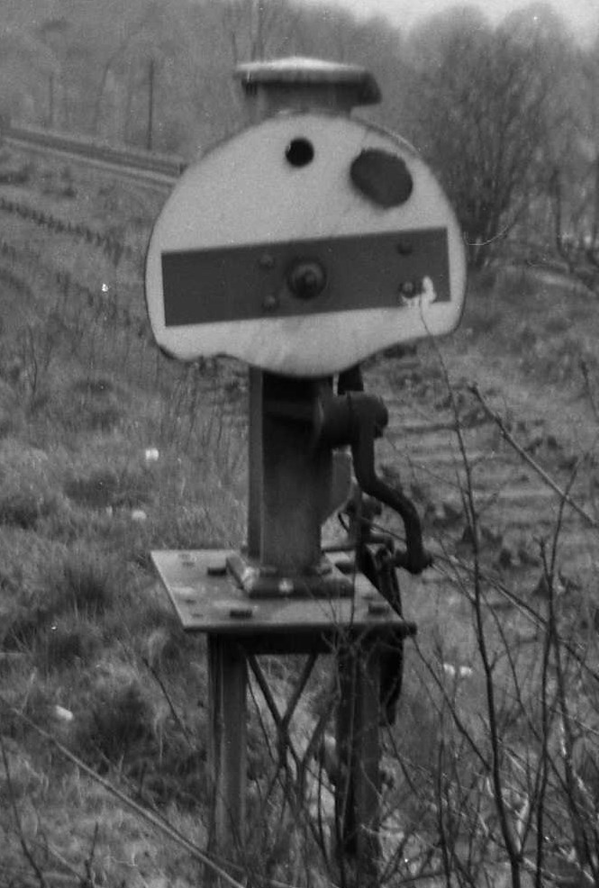
 As described above, it is believed that ground
signals 12PULL and 12PUSH
were provided when the colliery siding was opened in 1900, and signals 11PULL
and 11PUSH probably shortly thereafter. It
is not known if those signals were initially of the 'flap' type, or whether
the S&DJR had already started to use a 'miniature arm' version by that time,
although clearly the latter was used in 1910 (SI 216). The locations of the
various ground signals meant that they rarely appeared in photographs, with the exception of 12PUSH which was prominent in the 'six foot' in many pictures of the Radstock end
of the station (although curiously only in the BR period). It would appear
that in due course signals 11PULL, 11PUSH
and 12PULL were replaced by the SR 'half disc' type;
the left-hand image shows an example of that type (elevated on a short
lattice post) used as Norton Hill Colliery GF signal 1.
As described above, it is believed that ground
signals 12PULL and 12PUSH
were provided when the colliery siding was opened in 1900, and signals 11PULL
and 11PUSH probably shortly thereafter. It
is not known if those signals were initially of the 'flap' type, or whether
the S&DJR had already started to use a 'miniature arm' version by that time,
although clearly the latter was used in 1910 (SI 216). The locations of the
various ground signals meant that they rarely appeared in photographs, with the exception of 12PUSH which was prominent in the 'six foot' in many pictures of the Radstock end
of the station (although curiously only in the BR period). It would appear
that in due course signals 11PULL, 11PUSH
and 12PULL were replaced by the SR 'half disc' type;
the left-hand image shows an example of that type (elevated on a short
lattice post) used as Norton Hill Colliery GF signal 1.
At an unknown date (but possibly circa-1951 and certainly by April 1956) signal 12PUSH was replaced by a BR(WR) example with a 'full disc' face, and it was probably the first such BR(WR) ground signal on the S&DJR; whether this was a direct replacement for the earlier 'miniature arm' signal, or a later SR 'half disc', is unknown. A similar BR(WR) replacement was provided for 11PUSH at some time between August 1957 and May 1961; its location in the goods yard made it elusive in the photographic record, but a rear view of it can be seen in the right-hand image above.
When the Bath Extension was opened the block working on the single-line was by block telegraph without any physical train staff and, under the terms of the S&DR's 1874 undertaking to the BoT, Midsomer Norton was one of the block posts on the line. To the north (up the line) the next block post was at Radstock, whilst southwards (down the line) the next block post initially was at Binegar, but in 1876 a passing-loop and block post were opened at Chilcompton. Unlike some other single-line sections on the Bath Extension the line through Midsomer Norton was doubled before the introduction of Electric Train Tablet working in late 1886, so that system was never used there. The calling code for the station was 'E' on the 'speaking telegraph' circuit No 3 ('Highbridge Through'), although the code had changed to 'ET' by the time of the 1905 S&DJR WTT Appendix.
After the line was doubled through Midsomer Norton in 1886 (by which time the line from Chilcompton to Binegar had been doubled already in 1885) it is probable that the Radstock - Midsomer Norton and Midsomer Norton - Chilcompton block sections were worked by the standard 'block telegraph' equipment used by the S&DJR for Absolute Block working on double-track lines. Appendix 8 (1-October-1886) and Appendix 9 (1-February-1889) to the S&DJR WTT list a Special Dial Signal of 3 pause 3 on the needle to the left for a Light Engine to Radstock only, to be sent when the engine was entering the section, but that information did not appear in the 1905 WTT Appendix.
SI 39, issued on 29-November-1889, reported that Midsomer Norton was one of the signal-boxes which had been provided with a closing switch for the block telegraph system, enabling it to be 'switched out' each Saturday night until the following Monday morning; this facility would be brought into use from 7-December-1889 onwards. (Click here to read the full Instruction.) By the time of the 1905 WTT Appendix the SB was open every weekday from 6am until after the passing of the last stopping passenger train, but closed on Sundays. By contrast the SB at Chilcompton remained open until after the last train early on a Sunday morning and then re-opened at 8.30pm Sunday evening. It is clear from SI 108 that as from 21-November-1897 on Sundays the block section extended all the way from Radstock West to Shepton Mallet, as all the intervening SBs were switched-out.
The SB at Chilcompton was closed on 11-April-1965, after which the block section southwards became MIDSOMER NORTON - MOOREWOOD. However later that year Moorewood SB was closed on 5-July-1965 and the block section then extended further to become MIDSOMER NORTON - BINEGAR. Block working then remained unchanged until closure of the line on 6-March-1966.
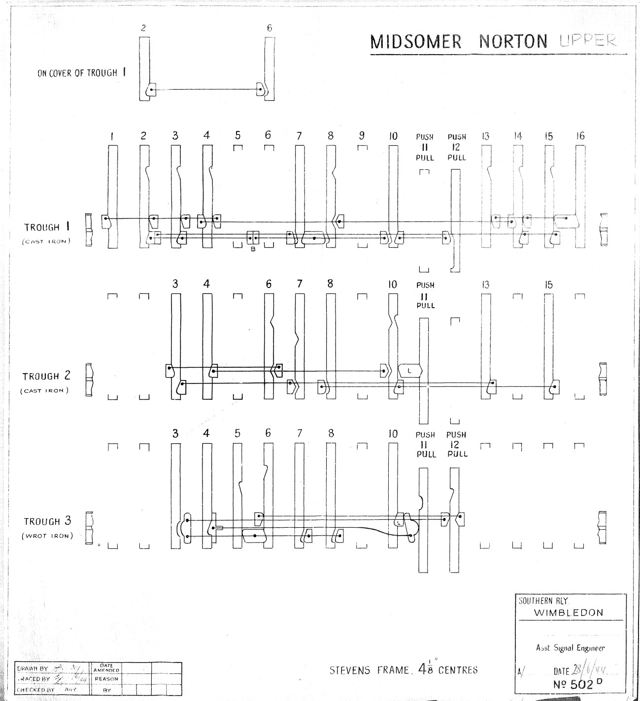
 The 1886 replacement SB was built to the same S&DJR TYPE 2 style as other
contemporary SBs on the Bath Extension; it had a timber
superstructure with vertical planking and distinctive 'wavy' barge-boards, on a
base of Mendip limestone which was set down into the Up platform near the
Chilcompton end. (Click the image on the left to see a larger photograph of the SB in the BR period.) It contained a 16-lever frame of the Stevens
4.1/8" pattern with 'direct tappet' interlocking; the actual manufacturer is not
known, but for that date it is likely to have been made by Stevens & Sons
themselves. After the various layout changes in the 1900-1910 period for the
addition of the colliery siding and various ground-signals, then it is
probable that any further interlocking alterations would have been very
minor. (Click
here to see the 'dog-chart' for the mechanical interlocking.)
Minute 5615 of the S&DJR Officers' Meeting on 25-April-1904 records that, as a
result of the opening of Norton Hill Colliery, the work at the SB had increased
and so it was agreed to raise the box from 3rd to 2nd class at an additional
cost of 1 shilling per week in wages. No other information is known about the SB
classification at any other period.
The 1886 replacement SB was built to the same S&DJR TYPE 2 style as other
contemporary SBs on the Bath Extension; it had a timber
superstructure with vertical planking and distinctive 'wavy' barge-boards, on a
base of Mendip limestone which was set down into the Up platform near the
Chilcompton end. (Click the image on the left to see a larger photograph of the SB in the BR period.) It contained a 16-lever frame of the Stevens
4.1/8" pattern with 'direct tappet' interlocking; the actual manufacturer is not
known, but for that date it is likely to have been made by Stevens & Sons
themselves. After the various layout changes in the 1900-1910 period for the
addition of the colliery siding and various ground-signals, then it is
probable that any further interlocking alterations would have been very
minor. (Click
here to see the 'dog-chart' for the mechanical interlocking.)
Minute 5615 of the S&DJR Officers' Meeting on 25-April-1904 records that, as a
result of the opening of Norton Hill Colliery, the work at the SB had increased
and so it was agreed to raise the box from 3rd to 2nd class at an additional
cost of 1 shilling per week in wages. No other information is known about the SB
classification at any other period.
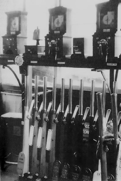 There
are very few known photographs of the SB interior during its operational life,
of which the image on the right (click for a larger photograph) taken
during the BR period is the best example. It is probable that by the early 1900s (if not in fact as part of the
original installation) the levers would have been fitted with
description
plates of the usual L&SWR/Stevens style of rectangular brass plates with
scalloped corners and raised brass lettering. Clearly some new plates would
have been required for those levers brought into use as a result of the
1900-1910 alterations. On 15-June-1945 the SR ordered a complete new set of
description plates in their contemporary
style of oval cast metal plates, painted in the appropriate colours for their
respective levers, with the descriptions sign-written on them in white paint
(black paint for spare levers and Distant signals). However the
order was amended on 2-August-1945 to change the descriptions for all the main
'stop' signals (2,3,4,13,14,15) to use LMS instead of SR terminology. It would
appear that during the BR period those 'stop' signals were re-labelled again, as the relevant levers
subsequently carried description
plates of the BR(WR) style (rectangular metal castings with engraved plastic
face-plates). Whilst the SR plates were fixed near the bottom of the
levers, the BR(WR) plates were fixed near the top, as can be seen in the
photograph.
There
are very few known photographs of the SB interior during its operational life,
of which the image on the right (click for a larger photograph) taken
during the BR period is the best example. It is probable that by the early 1900s (if not in fact as part of the
original installation) the levers would have been fitted with
description
plates of the usual L&SWR/Stevens style of rectangular brass plates with
scalloped corners and raised brass lettering. Clearly some new plates would
have been required for those levers brought into use as a result of the
1900-1910 alterations. On 15-June-1945 the SR ordered a complete new set of
description plates in their contemporary
style of oval cast metal plates, painted in the appropriate colours for their
respective levers, with the descriptions sign-written on them in white paint
(black paint for spare levers and Distant signals). However the
order was amended on 2-August-1945 to change the descriptions for all the main
'stop' signals (2,3,4,13,14,15) to use LMS instead of SR terminology. It would
appear that during the BR period those 'stop' signals were re-labelled again, as the relevant levers
subsequently carried description
plates of the BR(WR) style (rectangular metal castings with engraved plastic
face-plates). Whilst the SR plates were fixed near the bottom of the
levers, the BR(WR) plates were fixed near the top, as can be seen in the
photograph.
Based on available records, and extrapolating from other S&DJR SBs, then on the instrument shelf above the lever-frame (seen in the image above) and reading from left to right there were:-
Also on the instrument shelf at one time, positioned above levers 13 and 14, was a Sykes 'Indicator Lock' instrument. Lever 14 was fitted with a 'front-lock', which prevented the lever being pulled unless the instrument was showing 'FREE', while lever 13 had a 'back-lock', which prevented the lever being replaced fully to normal unless the instrument was showing 'FREE'. (In an emergency lever 13 could be put back sufficiently far for the signal arm to return to 'danger', but not enough to release the interlocking.) Whenever lever 14 was pulled for an Up train movement the indicator would change to 'LOCKED'; if then lever 13 was reversed as well, that would become back-locked. Once the train has passed the Up Starting signal (14) the signalman could return lever 14 to normal, but then it became front-locked so that it could not be pulled again. After the train had passed some distance beyond the Up Advanced Starting signal (13) it would operate treadle 'A', which would cause the Sykes instrument to show 'FREE' again and release both the back-lock on lever 13 (which then could be replaced) and the front-lock on 14. The Sykes locking then was returned to its normal state.
It is not known exactly when or why this Sykes locking was installed, but it was in existence by mid-1907. It is probable that its purpose was to prevent a train being signalled past 14 into the back of one already standing at the Up Advanced Starting (maybe awaiting the road to Radstock) and possibly out of sight of the signalman. (There was a similar Sykes installation on the Up line at Bailey Gate.) If a train then failed to pass beyond signal 13 (eg because it was shunted back across the east crossover 7 to the Down line) or the treadle failed to operate correctly, then the signalman would reset the Sykes instrument by use of a special Sykes 'release key'. After the abolition of treadle 'A' and the introduction of TC '14T', in the absence of any relevant locking records it is assumed that the Sykes instrument and locking were removed and new electric front and back locks fitted to lever 14 only. Lever 14 then would be front-locked unless the track-circuit was unoccupied, and then once reversed the back-lock would be released when the track-circuit became unoccupied again (eg after the train had passed beyond signal 13 or been shunted across the east crossover).
Records show that by 1949 signals 1, 13 and 16 were fitted with 'arm repeaters', whereby the 'on' or 'off' position of the signal arm would be repeated in the SB by means of electro-magnetic indicators mounted on the instrument shelf. It is probable that originally these indicators were the older rectangular pattern which stood on top of the shelf, but in BR days they were of the circular pattern fixed to the front of the shelf. (The circular indicator for signal 1 can be seen in this photograph in front of the block bell.) By 1952 additional arm repeaters had been provided for signals 12PUSH and 15, and signal 13 had gained also a 'lamp repeater' (which showed whether the oil-lamp for the signal arm was alight or not), but it is not known why additional repeaters were considered necessary at that time for those specific signals.
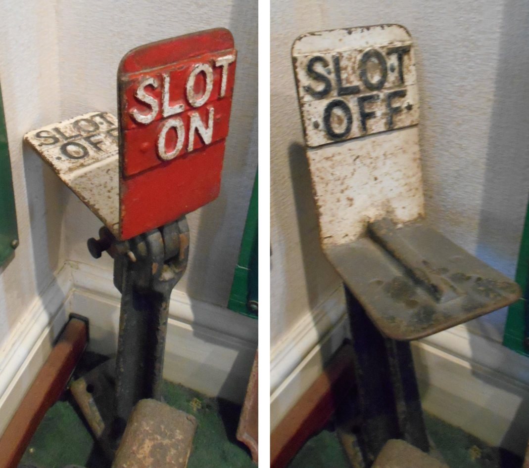
On the floor behind lever 5 there stood a mechanical 'slot indicator', which enabled the signalman to know when that lever had been unlocked by the GF and could be pulled to unbolt the colliery siding gate. When the indicator was normal, it displayed the words 'SLOT ON' in white on a red face, but when lever 1 in the GF was pulled the 'flap' would drop forwards to display the words 'SLOT OFF' in black on a white face. (Click here for a picture of a similar indicator in a private collection.) It is believed that the actual interlocking between the two levers was controlled by a lock mechanism adjacent to the GF, but the indicator was activated probably by wire from lever 1 in the GF. By BR days there was also a telephone in the SB for communication with the GF.
|
|
 |
||||||||||||||
| A typical 'flap' indicator | Mechanical Locking 'dog chart' | |||||||||||||||
| Click image for larger picture | Click image for larger picture | |||||||||||||||
Unlike some other locations on the S&DJR, Midsomer Norton appears to have suffered little (if any) rationalisation of its signalling installation during its final years. The station was closed to public goods traffic from 15-June-1964, but coal traffic continued until the closure of Norton Hill Colliery on 12-February-1966. The signal-box closed on 6-March-1966, when passenger services ceased on the whole of the S&DJR and the 'Bath Extension' was closed (except for the retention of short sections at Bath Junction and Radstock for goods traffic). Thereafter the station remained unused and increasingly derelict until the track was lifted in 1968/69. Both platforms remained in place, along with the station building, the goods-shed and the wooden shelter on the Up platform, but sadly the signal-box was demolished in 1973 and its stonework pushed over into the space within the platform. Another survivor was the Up Starting signal, which somehow remained standing at the end of the Up platform complete with its arm until it disappeared finally in mysterious circumstances about 1980. Bridge 48 over Silver Street was demolished in 1970 (in order to eliminate a height restriction on that road) and the site of Norton Hill Colliery was used eventually for a residential housing development.
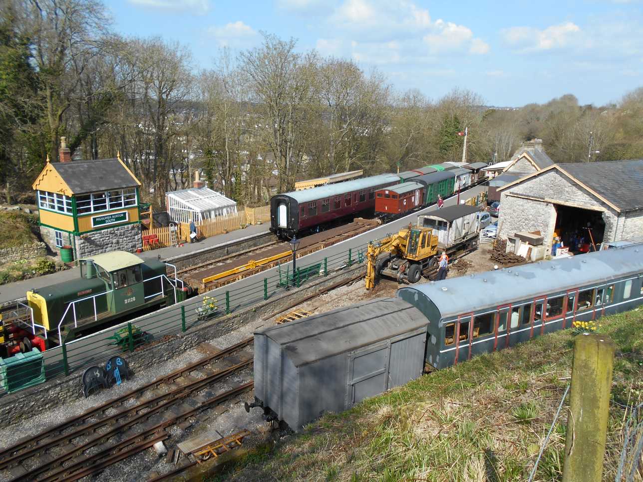
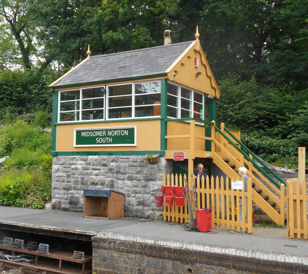
In 1969 the station site was acquired by the Somerset Education Authority and then sold in 1995 to the former Wansdyke District Council, who in turn leased it to the Somerset & Dorset Railway Heritage Trust (S&DRHT) in 1996. Since then the S&DRHT has restored the station buildings and platforms, and converted the goods-shed into a workshop, whilst the former stable-block at the rear of the goods yard has been converted into a museum. Track has been relayed at the station and the line is being extended southwards towards Chilcompton (extension towards Radstock is hampered by the lack of a bridge over Silver Street). The Type 2 signal-box has been recreated on its original site, including the re-use of the original stonework reclaimed from the demolished base; it houses a 26-lever Stevens & Sons lever-frame (recovered from the former L&SWR SB at Branksome), which is longer than the original in order to cater for the more extensive signalling now required for current-day operations. The new SB was commissioned in March 2016 (50 years after the closure of its predecessor) and there is now operational signalling once again at Midsomer Norton.
| Views of the restoration of Midsomer Norton station in 2015-17 | ||||||
 |
 |
 |
 |
|||
| Overview of the station | The new signal-box | Inside the new signal-box | Looking eastwards | |||
| Click pictures for larger images | ||||||
© CJL Osment 2018-23
Thanks to Steve Ehrlicher for material from the National Archives, to John Creed from details from
Signalling Record
Society archives, also Peter Russell and the late Peter McGhie. 1963 station photograph © Ian Scrimgeour
courtesy Signalling Record Society, old signal-box interior photograph M Deane, other
photographs variously Chandler, Rimmer and WCRA collections.
References
|
|
|||||||
| © West Country Railway Archives 2018 Page last updated: 05 April 2023 |
URL:
E-Mail: |
||||||


