


 |
Somerset &
Dorset Joint Railway Sykes Instruments and associated equipment |
|
||||||||
|
||||||||||
|
||||||||||
This page provides outline information and background details about the use of Sykes Instruments on the former Somerset & Dorset Joint Railway (S&DJR).
William Robert Sykes (a British signal engineer 1840-1913) is probably best known for his 'Lock and Block' system of block working, but he produced many other items of signalling equipment which were used for various purposes. Although the S&DJR did not use 'Lock and Block' working anywhere, there is evidence to suggest that at least some of the treadles used on the line were of Sykes manufacture, and possibly also the automatic disengager fitted to a signal at Wellow. The former Southern Railway used many Sykes brass-cased circular indicators for arm and lamp repeaters etc and it is probable that most, if not all, of those installed on the S&DJR in later years were made by Sykes.
However the term 'Sykes Instrument' is used normally to refer to a particular style of large wooden-cased instrument, such as those used for 'Lock and Block' working (examples of which can be seen in the photograph below), rather than the wider range of miscellaneous signalling items manufactured by Sykes. That convention will apply in these notes, which deal specifically with the variants of such 'Sykes Instruments' which are known, or believed, to have been used on the S&DJR. There are very few specific references to Sykes instruments in known official S&DJR records, and only two S&DJR signal-boxes for which interior photographs exist showing such instruments in place. Therefore much of the information regarding the possible use of Sykes instruments on the S&DJR has been deduced from the study of surviving copies of S&DJR signal-box diagrams, electrical locking tables and other signalling-related documents.
|
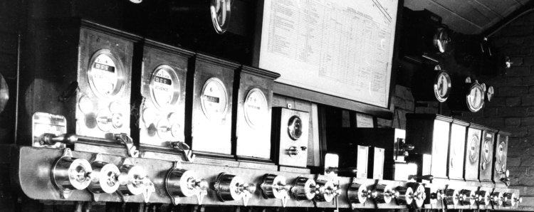
| An array of various Sykes Instruments in a Southern Railway signal-box |
For the purposes of discussion in RailWest the different types of Sykes instrument believed to have been used on the S&DJR have been classified as follows:-
Each type is described in more detail below - just click on the appropriate link above.
[Note: there is a remote possibility that a Sykes 'Train Waiting' indicator was provided at Blandford at one time. Until such time as any further information may become available, that type of instrument has been excluded from these notes.]
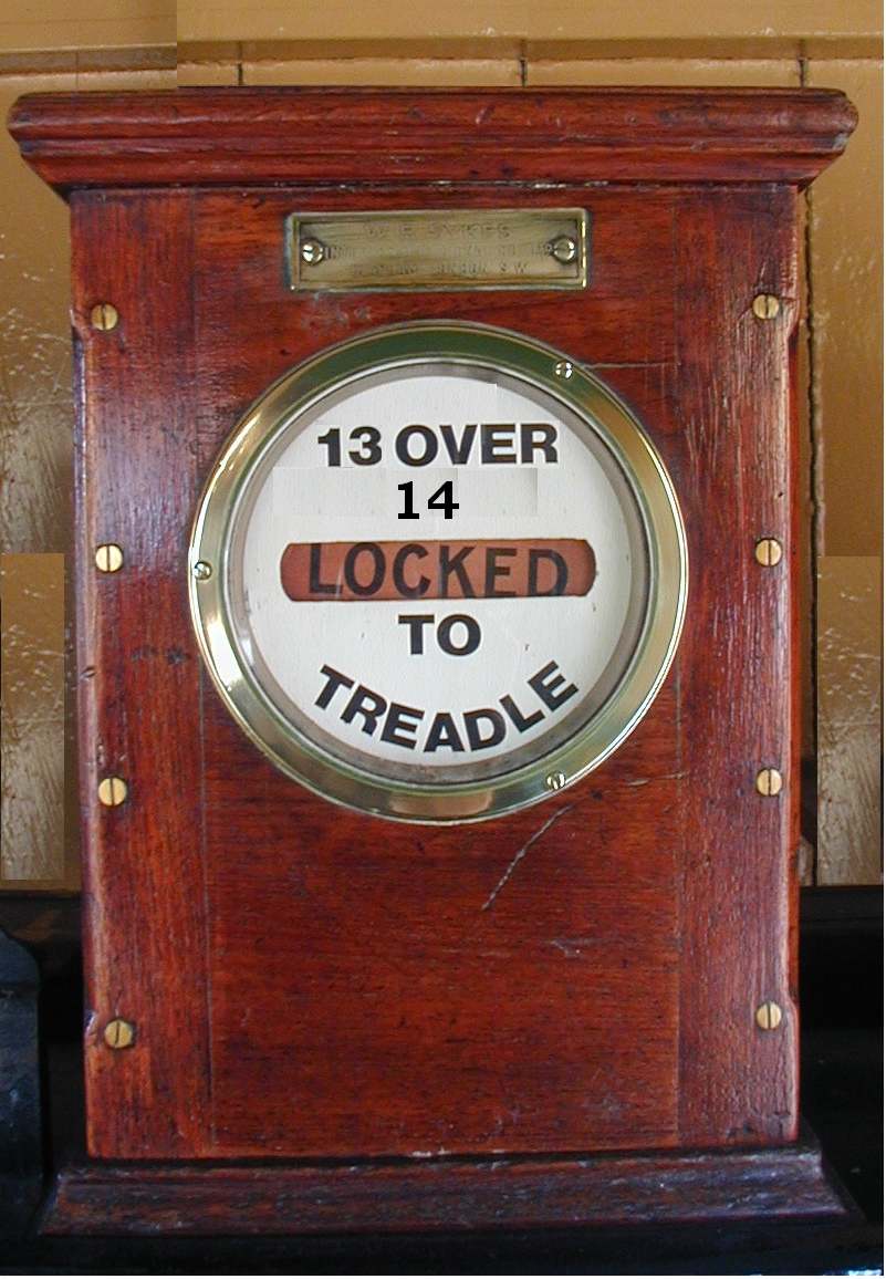
The different types of 'Sykes instrument' varied both in their external appearance and internal workings, but their general style was similar to the examples in the photograph above - a rectangular, wooden-cased instrument, with a glazed circular window in the front. Inside the window was a metal faceplate with either one or two rectangular apertures in its centre, through which various 'flags' would be visible. The legend on the faceplate would vary according to the individual installation. Some types of instrument also had one or two keyholes in the front of the case (normally covered by circular brass covers) for a 'Release Key', the use of which is described here.
The usual purpose of a 'Sykes instrument' was to provide an electrically-controlled lock on a lever in a signal-box lever-frame. An indication of the status of that lock ('locked' or 'free') was given by the information displayed through the faceplate aperture. The instrument would be mounted on the 'instrument shelf' above the lever-frame in the signal-box, and a circular metal down-rod would pass down through the signal-box floor and connect to a mechanical lock on the relevant lever. The down-rod was raised (usually) by a cam driven by the stroke of the lever, or fell by gravity when released by the instrument.
Sykes instruments would control either a 'front-lock' or a 'back-lock' (or both) on a lever. A 'front-lock' prevented a lever being pulled, whereas a 'back-lock' prevented a lever being replaced to normal. (As a precaution in case of an emergency a back-locked signal lever could be put back sufficiently far for the signal arm to return to 'danger', but not enough to release the interlocking for a conflicting movement.) If the instrument controlled locks on more than one lever (and these could be a mix of front and back locks), then typically there would be a single down-rod to one lever with horizontal linkage to the lock(s) on the other lever(s). Some additional interlocking might be provided by means of a 'Point and Plunger Lock', the use of which is described here.
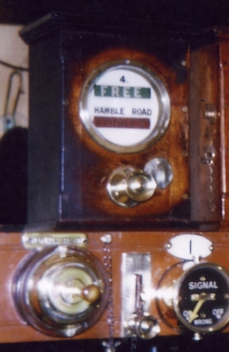
 An 'Indicator Lock' instrument was perhaps the most common form of Sykes
instrument and a typical example is illustrated here.
Inside the instrument there was a vertical flat metal 'lock blade', to the
front of which was fixed a rectangular thin metal plate. The top half of the
face of the plate was painted green, the bottom half red; on the top half was
written the word 'FREE' in white, on the bottom half the word 'LOCKED' in black.
The lock-blade could slide up or down - when up the legend 'LOCKED' was visible through the faceplate aperture,
when down then 'FREE' was displayed.
Movement of the lock blade might also open or close one or more sets of
electrical contacts within the instrument, which could be linked to external
circuits. The lock-blade extended through the bottom of the instrument and the instrument
shelf and was connected to the down-rod to the actual lever lock. The lock-blade was held in the up position by a latch kept in place
by a large permanent magnet at the rear of the instrument. To release the
lock-blade an electric current was applied to a set of electro-magnetic 'lock
release' coils,
which counteracted the magnet and released the latch, thereby allowing the
blade and its drop-rod to fall by gravity.
An 'Indicator Lock' instrument was perhaps the most common form of Sykes
instrument and a typical example is illustrated here.
Inside the instrument there was a vertical flat metal 'lock blade', to the
front of which was fixed a rectangular thin metal plate. The top half of the
face of the plate was painted green, the bottom half red; on the top half was
written the word 'FREE' in white, on the bottom half the word 'LOCKED' in black.
The lock-blade could slide up or down - when up the legend 'LOCKED' was visible through the faceplate aperture,
when down then 'FREE' was displayed.
Movement of the lock blade might also open or close one or more sets of
electrical contacts within the instrument, which could be linked to external
circuits. The lock-blade extended through the bottom of the instrument and the instrument
shelf and was connected to the down-rod to the actual lever lock. The lock-blade was held in the up position by a latch kept in place
by a large permanent magnet at the rear of the instrument. To release the
lock-blade an electric current was applied to a set of electro-magnetic 'lock
release' coils,
which counteracted the magnet and released the latch, thereby allowing the
blade and its drop-rod to fall by gravity.
One use for an Indicator Lock instrument was to control a front-lock on a signal lever, to ensure that the signal could not be cleared until some other action had taken place. In such a situation the lock-blade normally would be up, the instrument would display 'LOCKED' and the signal lever would be in its normal position with the front-lock engaged. When an electric current was applied to the 'lock release' coils the lock-blade would drop, the instrument would show 'FREE' and the front-lock would be disengaged to release the lever. When the lever was replaced to normal after the passage of the train then a 'backward motion' cam would raise the lock-blade, the instrument would show 'LOCKED' again and the front-lock would re-engage. An example of this arrangement existed at Wellow, where the lever for the Up Advanced Starting signal (6) was locked normal by an Indicator Lock instrument until such time as the signalman at Midford operated the plunger on his Plunger Lock instrument, which sent an electrical current down a line wire to the 'lock release' coils at Wellow.
Another use for an Indicator Lock instrument was to control a back-lock on a signal lever to ensure that, once a signal had been cleared for a train to proceed, it could not be replaced and then cleared again for a second train until the first train had been proved to have passed the signal. This was achieved by placing a treadle some distance in advance of the signal and connecting it electrically to the lock release coils in the instrument. The normal position for the instrument would be 'FREE', with the lock-blade down and the back-lock lifted on the signal lever. When the lever was pulled to clear the signal a 'forward motion' cam would raise the lock-blade, the instrument would show 'LOCKED' and the back-lock would be engaged to prevent the lever from being replaced fully to normal. After a train had passed the signal it would actuate the treadle and the current to the lock release coils would allow the lock-blade to drop, which would lift the back-lock and change the instrument display back to 'FREE', after which the lever could be returned to its normal position. Examples of this arrangement could be found on signals at Bailey Gate and Midsomer Norton.
[NOTE: Photographic and documentary evidence of Midford show that the indicator lock instrument there (which back-locked signals 3 and 13) showed 'LOCKED' when normal even though, as there were no front-locks, the levers were free of the Sykes locking to be pulled. Instead of a forward-motion cam, there was a back-motion cam which raised the down-rod when the lever was replaced fully after the back-lock had been released by the treadle. It is possible that this was a residual situation after modification of an earlier arrangement and it may not be typical of other S&DJR installations.]
It would appear that an Indicator Lock instrument was used at Spetisbury to control a front-lock on lever 6 (which worked the crossover points at that location) as part of the unusual arrangements there for controlling the switching in/out of the signal-box as a block post (click here for more details), but the precise details are unknown. In this instance it was not possible to use a back-motion cam to reset the instrument, as the point lever might not actually be used while the signal-box was open, so it would appear from the relevant Special Instructions that it was reset by means of a separate small Sykes lever provided for that purpose. In effect that lever provided the same function as the 'lift handle' of a Lift To Plunge instrument, but no further details are known about it.
 As implied by its full name 'Indicator Lock and Plunger Instrument', this was
essentially an Indicator Lock instrument with the
addition of a plunger, which was fitted centrally on the front of the instrument below
the indicator window. There was also a second,
lower aperture in the window faceplate, which would display (usually) either a
'blank' white indication or the words 'TRAIN ON' in black on a white
background. To the right of the plunger was a 'release key'
keyhole and below that was a 'switch hook', which the signalman could
rotate anti-clockwise to place over the shaft of the plunger as a visual and
physical reminder to prevent use of the plunger. (Rotation of the switch-hook
also opened or closed electrical contacts within the instrument.) A further
'reminder' device was provided in the form of a small brass disc engraved
'LINE BLOCKED' with a projecting brass pin, which was kept in a receptacle on
the left-hand side of the instrument, to which it was attached by a short
brass chain. When the switch-hook was placed over the plunger the signalman
could insert the pin of the 'Line Blocked' disc through the end of the
switch-hook, so that it could not be rotated clockwise away from the plunger.
As implied by its full name 'Indicator Lock and Plunger Instrument', this was
essentially an Indicator Lock instrument with the
addition of a plunger, which was fitted centrally on the front of the instrument below
the indicator window. There was also a second,
lower aperture in the window faceplate, which would display (usually) either a
'blank' white indication or the words 'TRAIN ON' in black on a white
background. To the right of the plunger was a 'release key'
keyhole and below that was a 'switch hook', which the signalman could
rotate anti-clockwise to place over the shaft of the plunger as a visual and
physical reminder to prevent use of the plunger. (Rotation of the switch-hook
also opened or closed electrical contacts within the instrument.) A further
'reminder' device was provided in the form of a small brass disc engraved
'LINE BLOCKED' with a projecting brass pin, which was kept in a receptacle on
the left-hand side of the instrument, to which it was attached by a short
brass chain. When the switch-hook was placed over the plunger the signalman
could insert the pin of the 'Line Blocked' disc through the end of the
switch-hook, so that it could not be rotated clockwise away from the plunger.
Although Plunger Lock instruments were similar in external appearance, they could vary considerably with their internal construction. The only known example of a Plunger Lock instrument on the S&DJR was installed at Midford, where it was used in conjunction with the normal block working of the Up Line of the double-track from Wellow. That instrument was a variant known as 'Plunge When Free' and it had a second 'release key' keyhole to the left of the plunger. The picture shows the actual instrument from Midford (now in a private collection) with a release key inserted in the right-hand keyhole. Each keyhole was covered by a circular brass plate, on which was engraved an arrow to show the direction in which the key had to be turned.
[Note: the brass components seen at bottom centre of the Midford instrument relate to the 'Point and Plunger Lock' feature described below. These are not the original items, but replacements provided after the instrument passed into private hands, and so the descriptive information on the large rectangular brass plate is incorrect for Midford. Also the projecting handle has broken off and only the stub is visible!]
The information given on this page about Plunger Lock instrument operation is specific to the Midford instrument, but the general principles may be applied to other versions. Inside the instrument there was a 'lock blade' similar to that of the ordinary Indicator Lock instrument and this carried the indications for the upper aperture. There was also a separate 'click blade', which carried the indications for the lower aperture, but unlike the lock-blade the click-blade was not usually connected to any down-rod. A third 'resetter blade' was connected to a down-rod to the relevant lever(s), but this blade did not carry any visual indicators. The click-blade was held in the up position by a latch over the resetter-blade when that too was in the up position. The design of the blades and plunger was arranged such that the plunger could only be depressed by the signalman when all the blades were in the required position.
When the instrument at Midford was 'normal' then the lock-blade would be down and the upper indicator would display 'FREE'. Both the click-blade and resetter-blade would be up, so the lower indicator displayed the blank indication. When the plunger was pressed it disengaged the latch on the click-blade from the resetter-blade, allowing the former to drop and display 'TRAIN ON'. (Depression of the plunger also closed a set of electrical contacts to sent an electric current to Wellow, in order to release the Indicator Lock instrument on the Up Advanced Starting signal there, but that function is not relevant to the working of the instrument at Midford.) A spring would return the plunger outwards, but once the click-blade was down then it prevented the plunger from being pressed a second time.
When the signalman pulled the appropriate lever to clear his Home signal a 'forward motion' cam would raise the lock-blade, causing the upper indicator to show 'LOCKED', and apply a back-lock to the signal lever. (In its up position the lock-blade also prevented the operation of the plunger.) After the train had passed the signal it activated a treadle, which would send current to the lock release coils to allow the lock-blade to drop, lift the back-lock on the signal lever, and change the upper indicator to 'FREE'. When the signalman restored the relevant lever to normal a 'back motion' cam raised the resetter-blade, which in turn lifted the click-blade so that the lower flag changed back to a blank display. The instrument was now in a state where the plunger was free to be used again as required.
[Note: The Sykes interlocking at Midford was quite complex and specific to that location, so the preceding description is a simplified explanation to explain the basic functionality of the instrument. It is hoped to provide more detailed information about the actual Midford installation on the relevant RailWest page in due course.]
It is possible that a Plunger Lock instrument was provided also at Blandford when the line from there to Bailey Gate was doubled in 1901, as a drawing prepared by WR Sykes in late 1900 shows what appears to be such an instrument associated with the Up Home signal. It is not clear whether that instrument was linked to the known provision of 'Train Waiting' gear for that signal and/or was involved in any way with the block working of Up trains from Spetisbury.
The 'Lift to Plunge' instrument was a variant of the 'Plunger Lock' instrument in which, in order to 'plunge' on the instrument, the signalman had first to raise a handle which projected through a vertical slot in the front of the instrument shelf below the instrument - hence its name. This type of instrument appears to have been used for a variety of purposes by various railway companies, but in the case of the S&DJR it was used in two locations for the release of a ground-frame (GF) which controlled an intermediate siding within a double-line block section.
Old Down Siding GF was on the Up line between Binegar and Chilcompton and controlled a siding which serves the Emborough stone works. This GF was released by Binegar and it existed from 1900 until 1914, when it was superseded by the new Moorewood signal-box. Downside Siding GF was on the Down line between Winsor Hill and Shepton Mallet and controlled a siding which served Downside Colliery; it was released by Winsor Hill and existed from 1900 until 1940, when the GF and siding were abolished. In both cases the release mechanism for the GF consisted of a 'Lift to Plunge' instrument in the controlling signal-box (SB) and another such instrument at the ground-frame. There would also have been a bell in the SB worked by a bell-push at the GF, and a bell at the GF worked by a bell-push at the SB, to provide communication between the signalman and the guard or shunter operating the GF.
At both GF locations the lever-frame was housed in a small wooden hut, but the Sykes instrument and bell would have been installed in a box fixed to the outside of the hut. It was a feature of such installations that the Sykes instrument locked the door of the hut as well as the actual lever-frame, so it was necessary for the person operating the GF to have access to the Sykes instrument before entering the hut (and again after leaving upon completion of using the GF). It was the practice also to provide 'home' and 'distant' signals on the relevant line at the approach to the GF, which would be worked from the GF but normally left in the 'off' position. The GF operator would have to put these signals back to 'on' before the siding points could be operated, and then pull them 'off' again once he was ready to lock-up the GF afterwards.
 There are no known photographs of the relevant
S&DJR instruments, but the picture here shows a 'Lift to
Plunge' instrument in use for GF release purposes in a signal-box elsewhere on the former
Southern Railway. It is
similar in appearance to the Plunger Lock instrument with two apertures in
the front face-plate, but it does not have a 'switch hook', and the 'lift' handle can be seen projecting
through the slot in the front of
the instrument shelf. [Note: ignore the large plunger to the left and the
'signal' indicator to the right, which are not relevant to the Sykes
instrument.] There was also just a single 'release key'
keyhole in the front of the instrument to the right of the plunger.
There are no known photographs of the relevant
S&DJR instruments, but the picture here shows a 'Lift to
Plunge' instrument in use for GF release purposes in a signal-box elsewhere on the former
Southern Railway. It is
similar in appearance to the Plunger Lock instrument with two apertures in
the front face-plate, but it does not have a 'switch hook', and the 'lift' handle can be seen projecting
through the slot in the front of
the instrument shelf. [Note: ignore the large plunger to the left and the
'signal' indicator to the right, which are not relevant to the Sykes
instrument.] There was also just a single 'release key'
keyhole in the front of the instrument to the right of the plunger.
Above the upper aperture in the face-plate was the number of the signal which controlled access into the block-section (and therefore also protected the GF) whilst above the lower aperture was the name of the GF released by the instrument. On the corresponding instrument at the GF a photograph from a different Southern Railway location shows the legend 'Point Lever and Cabin Door' above the upper aperture, above the lower aperture was the description of the section signal at the controlling SB, and the actual name of that SB was below the lower aperture. Of course it is only speculation that the instruments on the S&DJR would have been labelled in a similar manner.
Please Note: It is unfortunate that no suitable 'Lift to Plunge' instrument has been available for inspection, so it has been necessary to make certain assumptions regarding the probable internal arrangements and associated interlocking, based on comparison with 'Plunger Lock' instruments and information deduced from the operating instructions for the two relevant S&DJR GF installations. Therefore the information in these notes about the construction and operation of the instrument is provided on a 'best guess' basis and should not be regarded as definitive.
Inside the instrument there would have been a 'lock blade' and at least one other blade (probably a 'click blade'). The lock-blade would carry the indications for the upper aperture and the other blade would carry the indications for the lower aperture (in a similar fashion to the Plunger Lock instrument). The instrument in the signal-box (SB) would have a down-rod connection from the lock-blade to a front-lock on the signal which controlled access into the block section, whereas at the GF there would be a connection from the lock-blade to the locks on the door of the GF hut and the actual lever-frame. When the installation was in its 'normal' state and the GF was locked, then the lock-blade in the SB instrument would be down, the instrument would display 'FREE' in its upper aperture, and the front-lock on the section signal would be 'off'. (It is assumed that this lock was required only when the GF was in use, so in normal day-to-day working the signal lever would be free and could be pulled and replaced without affecting the Sykes instrument.) The lower aperture would show 'LOCKED' (meaning that the GF was locked) but it is unclear whether the relevant blade was up or down. However at the GF instrument the lock-blade would normally be up, so the upper aperture would display 'LOCKED' and the door to the GF hut would be locked. The position of the other blade and the indication displayed in the lower indicator is unclear, but it is believed that it showed 'FREE' to indicate the status of the section signal at the controlling SB.
In order to release the GF, with the lever in the SB for the 'section signal' in its normal position the signalman would lift the handle below his Sykes instrument. This would raise the lock-blade and engage the front-lock on the signal lever, thereby preventing another train from being signalled incorrectly into the block section while the GF was in use. With the lock-blade in the up position the upper indicator would show 'LOCKED' and the plunger would be free to move. When the signalman pressed the plunger this sent an electric current to the release coils in the instrument at the GF, where the lock-blade would then drop and release the lock on the GF hut door, and also change the upper indicator in that instrument to 'FREE'. It is assumed that the operation of the plunger also caused the lower indicator in the SB instrument to change to 'FREE', and the lower indicator in the GF instrument to change to 'LOCKED', but this can not be confirmed.
When work at the siding was complete the GF operator would reset the lever-frame to its normal state, then leave the hut and close the door. He would then lift the handle beneath the GF instrument, which would raise the lock-blade, change the upper indicator back to 'LOCKED' and lock the hut door. With the lock-blade raised he could then press the plunger, which would send electric current to the release coils in the SB instrument, where the lock-blade would drop, change the upper indicator in the SB instrument to 'FREE' and disengage the front-lock on the section signal lever. It is assumed that at the same time the lower indicator in the SB instrument changed to 'LOCKED', and the lower indicator in the GF instrument changed to 'FREE', but it is unclear how this would have happened. Both instruments would now be back to their normal condition and the GF would be locked.
Click here to read the operating instructions for Old Down Siding GF from the 1905 S&DJR Appendix to the Working Time Tables.
Where a Plunger Lock instrument was used in conjunction with a Home signal for the block working to the next SB in rear, then it was common to provide interlocking between that instrument and any points within the 'clearing point' in advance of that signal. This ensured that the signalman could not obstruct the clearing point (by reversing any of the points) after he had accepted a train from the SB in rear, nor could he accept a train if any points in advance of the signal were not in the correct position. This interlocking was achieved by means of a Sykes 'Point and Plunger Lock', sometimes referred to colloquially as a 'P&P lock'.
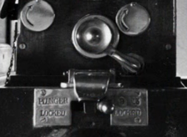 A P&P lock usually took
the form of a small horizontal handle which was mounted underneath the Plunger
Lock instrument, with the handle projecting through a slot cut in the front of
its base and/or the front of the instrument shelf. When the lever was moved to
the left of the slot then the plunger was locked, so that instrument could not
be used to accept a train, but the lever(s) for the relevant point(s) would be
free to be worked; conversely when the lever was moved to the right of the
slot then the plunger would be free, but the point levers would be locked.
(It is unfortunate that no intact P&P lock has been available for inspection,
so it is unclear exactly how the mechanism interacted with the Plunger Lock
instrument.) There was usually a small 'drop flap' provided above the lever
which kept it in one or other position. The slot for the P&P handle had a
brass plate surround, with the left-hand side engraved 'PLUNGER LOCKED'; the
right-hand side would be engraved 'N LOCKED'
(or similar wording), where 'N' was the number(s) of the lever(s) locked
by the P&P lock. The only known instance of a P&P lock on the S&DJR was fitted to the Plunger
Lock instrument at Midford; the picture here shows a typical P&P lock handle arrangement at a
Southern Railway location.
A P&P lock usually took
the form of a small horizontal handle which was mounted underneath the Plunger
Lock instrument, with the handle projecting through a slot cut in the front of
its base and/or the front of the instrument shelf. When the lever was moved to
the left of the slot then the plunger was locked, so that instrument could not
be used to accept a train, but the lever(s) for the relevant point(s) would be
free to be worked; conversely when the lever was moved to the right of the
slot then the plunger would be free, but the point levers would be locked.
(It is unfortunate that no intact P&P lock has been available for inspection,
so it is unclear exactly how the mechanism interacted with the Plunger Lock
instrument.) There was usually a small 'drop flap' provided above the lever
which kept it in one or other position. The slot for the P&P handle had a
brass plate surround, with the left-hand side engraved 'PLUNGER LOCKED'; the
right-hand side would be engraved 'N LOCKED'
(or similar wording), where 'N' was the number(s) of the lever(s) locked
by the P&P lock. The only known instance of a P&P lock on the S&DJR was fitted to the Plunger
Lock instrument at Midford; the picture here shows a typical P&P lock handle arrangement at a
Southern Railway location.
One potential problem with Sykes instruments was the reliance on a certain sequence of operations executed correctly in a specific order - for example, a train passing over a treadle in order to reset an Indicator Lock instrument and release the back-lock on a signal lever. But if the treadle failed to release the instrument, or the train simply drew a short distance past the signal for shunting purposes but did not go as far as the treadle, then how was the Sykes interlocking to be reset? The answer lay with the special Sykes 'release key'.
The actual effect of using a release key varied between the different types of instrument. In the case of an 'Indicator Lock' instrument there was normally no release keyhole in the instrument itself, but instead it would be located usually in the front of the instrument shelf close to the Sykes instrument, and behind the keyhole there would be a set of normally-open electrical contacts. Turning the key would close the contacts and send a release current to the Sykes instrument in a similar manner to operation of the treadle, so the lock-blade would drop and change the display indication from 'LOCKED' to 'FREE'.
As described above, the 'Plunger Lock' instrument used at Midford has two release keyholes in its front, one each side of the plunger. If the release key was turned in the right-hand keyhole, then the key would physically lift the click-blade and therefore change the lower aperture back to the blank indication. If the key was turned in the left-hand keyhole, then it closed a set of electrical contacts inside the instrument which sent a current to the release coils for the lock-blade, which would drop and change the upper aperture back to the 'FREE' indication. By comparison, in a different version of the Plunger Lock instrument the use of the key in the left-hand keyhole physically moved the relevant latch to allow the lock-blade to fall.
The 'Lift to Plunge' instrument had a single release keyhole (on the right of the plunger). In the absence of any detailed knowledge of the internal arrangement, it is not clear exactly how the release key would have functioned in the S&DJR instruments. It is possible that it closed a set of electrical contacts, which operated the release coils for the lock-blade in a similar manner to what would have happened when the plunger was operated in the remote instrument. Alternatively, or perhaps additionally, it might have reset one or more blades mechanically.
Note: In the 1914 edition of the S&DJR Appendix to the Working Time Tables the instructions for Downside Siding included a reference to the use of a release key. In the event that, when the Guard or Shunter was locking-up the GF after use his plunge on the instrument failed to release the locking at Winsor Hill, then he had to insert and turn the release key in his instrument to 'adjust' it and then give a second plunge. It is possible that the release key action mechanically raised the blade which carried the 'flag' for the lower aperture to enable the plunger to be depressed again. However it is difficult to understand why the release key was used at the GF rather than at the SB, given that it was the SB instrument which needed to be unlocked. It is curious also that no similar information is contained within the instructions for Old Down Siding in the same Appendix.
An appropriate entry would be made in the Train Register by the signalman whenever he used a Sykes release key.
A Register is being compiled in RailWest which will list all instances of Sykes Instruments on the S&DJR, but completion will take some time as research is still underway. The Register currently gives details of all known Sykes instruments and also those whose existence is considered highly probable from the available evidence. There are other S&DJR locations where there may have been Sykes instruments at some time, but current information is inconclusive. Please Note therefore that the Register given here may prove to be incomplete.
Register entries are listed in line order of the signal-boxes or ground-frames at which the Sykes instruments were installed, but an alphabetical Index to Locations is provided also for quick access to individual signal-boxes or ground-frames. The following explanations of Register entries should be noted:-
| Index to S&DJR Sykes Instrument Locations | |||||
|---|---|---|---|---|---|
| Bailey Gate | Blandford | Downside Siding | Midford | Old Down Siding | Wellow |
| Binegar | Corfe Mullen Jcn | Evercreech Jcn North | Midsomer Norton | Spetisbury | Winsor Hill |
| Somerset & Dorset Joint Railway Sykes Instrument Register | |||||||||||||
|---|---|---|---|---|---|---|---|---|---|---|---|---|---|
| Location | Type | Date | Remarks | ||||||||||
| Midford | IL | circa-1900 | Back-locks on signals 3 and 13, released by treadles 'A' or 'B'. Back-lock on 3 removed in 1952. | ||||||||||
| PL | circa-1900 | Back-locks on signals 5PULL, 12 and 15, released by treadle 'C'. Plunger released lock on Up Line block instrument commutator, and also Up Advanced Starting at Wellow. Fitted with P&P lock. | |||||||||||
| Wellow | IL | circa-1900 | Front-lock and back-lock on signal 6. Front-lock released by 'plunge' from PL at Midford, back-lock released by treadle 'A'. | ||||||||||
| Midsomer Norton | IL | by 1907? | Front-lock on signal 14 and back-lock on signal 13, released by treadle 'A'. Instrument abolished early 1950s? | ||||||||||
| Old Down Siding GF | LTP | 1900 | Lock for GF, released by 'plunge' from LTP at Binegar. GF abolished 1914. Note 4 | ||||||||||
| Binegar | LTP | 1900 | Release for Old Down Siding GF and front-lock on signal 21. Abolished 1914? Note 4 | ||||||||||
| Winsor Hill | LTP | 1900 | Release for Downside Siding GF and front-lock on signal 15. Abolished 1940? | ||||||||||
| Downside Siding GF | LTP | 1900 | Lock for GF, released by 'plunge' from LTP at Winsor Hill. GF abolished 1940. | ||||||||||
| Evercreech Jcn North | IL | 1911? | Back-locks on signals 26PUSH, 26PULL and 28, released by treadle. Instrument abolished post-1930? | ||||||||||
| Blandford | PL? | 1901 | A Sykes drawing shows a probable Plunger Lock instrument, but its purpose is unclear and may have been related to the known provision of 'Train Waiting' gear on signal 2. | ||||||||||
| Spetisbury | IL? | 1901 | Front-lock on points 6 when signal-box switched 'out'. Probably removed when crossover abolished circa-1918. Note 3 | ||||||||||
| Bailey Gate | IL? | 1901 | Back-lock on signal 15, released by treadle 'A'. Note 1 | ||||||||||
| Corfe Mullen Junction | IL? | 1905 | Back-locks on signals 2 and 4, released by treadles 'B' or 'C'. Note 1 Note 2 | ||||||||||
| IL? | 1905 | Back-locks on signals 18 and 20, released by treadle 'A'. Back-lock on 18 abolished 1933? Note 2 | |||||||||||
| |||||||||||||
© CJL Osment 2015-23
Southern Railway instruments and P&P lock photographs
© Ian Scrimgeour courtesy Signalling
Record Society, Lift-to-Plunge instrument photograph © Chris Hunt, all other photographs © CJL Osment. Acknowledgements to all
those who have contributed background information on Sykes instruments.
| © West Country Railway Archives 2015 Page last updated: 29 March 2023 |
URL:
E-Mail: |
||||||


