


 |
Somerset &
Dorset Joint Railway Treadles |
|
||||
|
||||||
This page provides a Register of all the known electrical Treadles on the former Somerset & Dorset Joint Railway (S&DJR).
It is not known if any official records survive which list all the S&DJR treadles. The information contained in this Register has been compiled by studying surviving copies of S&DJR signal-box diagrams, on which usually any treadles were marked, and other railway documents. It is quite possible that there may have been treadles which were removed in earlier years and therefore do not appear in the updated signal-box diagrams which survive from a later period.
There were variations in the method of identification of treadles on signal-box diagrams. Where more than one treadle existed at one location, then usually they were identified simply by letters, a separate sequence 'A' 'B' 'C'... etc being used at each signal-box. (There were some locations where the sequence did not use contiguous letters.) Where there was just one treadle, then it might be labelled 'A' or just simply 'Treadle'. Sometimes the function of the treadle was used instead as a description, eg 'Train Waiting treadle'. It should be noted that at some locations which had both treadle and track-circuits a single labelling sequence was used for both types of equipment, whereas at other locations separate sequences were used for the different types.
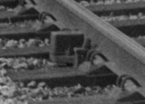
In simple terms a 'treadle' was an electrical switch located in the track and operated by a passing train. Treadle design has varied over the years, but many older types were fixed to the outside of, or underneath, a rail and operated by the deflection of the rail under the weight of the train. The design of the treadle amplified the small amount of rail deflection in order to provide adequate movement to operate the electrical contacts, which might be 'rubbing' or 'wiping' spring contacts or encapsulated mercury contacts. By their nature treadles are elusive items in the S&DJR photographic record, but certainly two different patterns could be found in photographs of Midford.
| Examples of S&DJR Treadles | ||
 |
 |
|
| Treadle 'C' at Midford | Treadle 'E' at Midford | |
| {Click thumbnail to see larger image} | ||
Both types of treadles illustrated are believed to be Sykes equipment. Photographic evidence suggests that treadle 'B' at Blandford and the three treadles at Corfe Mullen Junction were similar to treadle 'E' at Midford.
The depression of a treadle either closed or opened a set of electrical contacts, the difference depending upon the nature of the circuit to which the treadle was connected. (The style of symbol used on the signal-box diagram indicated which variation applied to each individual treadle.) On the S&DJR it would appear that most treadles had 'normally open' contacts, as their function usually was to send a pulse of current to release some form of lock mechanism after the passage of a train. If the treadle failed to operate correctly, or there was a break in the electrical circuit, then there would be a 'fail safe' condition as the lock simply would not release.
One S&DJR example of a treadle with 'normally closed' contacts was Treadle 'E' at Midford, located in rear of the Up Outer Home signal 15. As well as operating a 'Train Waiting' indicator in the signal-box the treadle was interlocked also with the block controls for Up trains from Wellow, to ensure the safety of any train waiting at the signal. Although it was not possible to mitigate any failure of the treadle itself to operate, any break in the circuit would have the same effect as a treadle operation and therefore activate the locking accordingly, hence providing a 'fail safe' condition.
When a train passed over a treadle then the treadle would be depressed by a wheel on the first axle in the train and continue to be operated by each successive axle until the complete train had passed. For most purposes the initial depression was the important operation, as this activated the relevant circuit and registered the fact that the train had reached the location of the treadle - any subsequent current passing in the circuit had no further effect. However in some circumstances it was necessary to detect when the end of a train had passed, in which case a special 'Last Vehicle Treadle' (LVT) was used. A LVT was constructed in such a way that the electrical contacts were operated, not by the action of depression, but when the treadle returned to normal after the last axle had passed. The only known S&DJR example of a LVT was Treadle 'B' at Midford.
Another variant of treadle was the 'electric fouling bar' (EFB), a long flat metal bar fixed parallel to the inside face of a rail and pivoted on its longitudinal axis. The bar had counter-balanced weights arranged such that, when the EFB was 'normal', it was in a raised position where it fouled the flangeway, so that it was depressed by the wheels of any train passing over it. EFBs tended to be used in situations where it was required to detect the presence of stationary trains, whereas other types were used mostly to register the passage of moving trains past a particular location. Records indicate that there was an EFB at Evercreech Junction South in Southern Railway days, but it was replaced by a track-circuit circa-1949.
Unlike track-circuits it was not the practice to repeat the status of a treadle in the signal-box. Normally the activation of a treadle would be self-evident within the signal-box because of the effect on some other item of equipment, such as the sounding of a warning buzzer or changing the display on a lock indicator etc.
The Treadle Register entries are listed in the line order of the various relevant signal-boxes, but an alphabetical Index to Locations is provided also for quick access to individual signal-boxes.
The following explanations of Treadles Register entries should be noted:-
Key: EFB=Electric Fouling Bar, NC='Normally Closed' contacts, TC=Track-Circuit, TW=Train Waiting.
| Index to S&DJR Treadle Locations | ||||
|---|---|---|---|---|
| Bailey Gate | Evercreech Jcn North | Midford | Sturminster Newton | Wellow |
| Blandford | Evercreech Jcn South | Midsomer Norton | Templecombe 'B' | |
| Corfe Mullen Jcn | Evercreech New | Radstock West | Waterloo Road | |
| Somerset & Dorset Joint Railway Treadle Register | |||||||||||||||||||||
|---|---|---|---|---|---|---|---|---|---|---|---|---|---|---|---|---|---|---|---|---|---|
Location |
ID |
Date |
Remarks |
||||||||||||||||||
| Midford | A | By 1914 |
On single line in advance of Up Starting 13 (believed to be north of goods yard points). | ||||||||||||||||||
| B | LVT on Down line in advance of facing points 8, just beyond start of TC 'A'. (Removed 1952 when TC 'B' installed.) Note 2 | ||||||||||||||||||||
| C | On Up line in advance of Up Outer Home 15, between Up Siding points and Up Inner Home 14. | ||||||||||||||||||||
| E | TW NC treadle on Up line in rear of Up Outer Home 15. | ||||||||||||||||||||
| Wellow | A | By 1930 | On Up line in advance of Up Advanced Starting 6. | ||||||||||||||||||
| Radstock West | By 1932 | On Up line in rear of Up Main Distant 31. (May have been replaced by TC by 1962.) | |||||||||||||||||||
| Midsomer Norton | A | By 1906 | On Up line 100 yards in advance of Up Advanced Starting 13. (Superseded in BR period by new TC in rear of Up Advanced Starting 13.) | ||||||||||||||||||
| Waterloo Road | A | 1947 | On Down line in advance of south crossover points. | ||||||||||||||||||
| B | On Up line in advance of north crossover points. | ||||||||||||||||||||
| Evercreech New | By 1914 | Four treadles, two each on Up and Down lines. One near Distant signal, the other a short distance in advance of station footpath crossing. Note 7 | |||||||||||||||||||
| Evercreech Jcn North | Post-1903, by 1911, gone by 1930 | On Up line between trailing end of siding points 19 and facing point 16. Note 3 | |||||||||||||||||||
| Post-1911, by 1930, gone by 1949 | On Up Main between Down Branch crossing and crossover points 14. Note 4 | ||||||||||||||||||||
| On Up Branch between facing points 16 and crossover points 11. Note 4 | |||||||||||||||||||||
| Evercreech Jcn South | B | EFB on Up line near the Bath end of the platform. (Superseded by TC 'B' circa-1949.) | |||||||||||||||||||
| Templecombe 'B' | A | By 1930 | On Up line in advance of Up Advanced Starting 4. | ||||||||||||||||||
| Sturminster Newton | A | Note 5 | On single line at or near Down Distant 1. | ||||||||||||||||||
| C | On Up loop line south of Blandford end of platform. | ||||||||||||||||||||
| E | On single line at or near Up Distant 16. | ||||||||||||||||||||
| Blandford | TW | By 1913 | TW NC treadle in rear of Up Home 2. | ||||||||||||||||||
| B | On Up line in advance of Up Siding No 1 points 8. | ||||||||||||||||||||
| Bailey Gate | A | 1901 | On Up line in advance of Up Advanced Starting 15. Note 6 | ||||||||||||||||||
| Corfe Mullen Junction | A | 1905 | On Up line in advance of trailing end of north crossover points 7. | ||||||||||||||||||
| B | On Wimborne line in rear of Up Branch Home 18. Note 8 | ||||||||||||||||||||
| C | On Broadstone line in rear of Up Main Home 20. Note 8 | ||||||||||||||||||||
| |||||||||||||||||||||
© CJL Osment 2013-2018
Treadle 'C' photograph © Philip Horton, Treadle 'E' photograph © Norman Lockett
| © West Country Railway Archives 2013 Page last updated: 02 August 2018 |
URL: http://www.railwest.org.uk E-Mail: railwest@bigfoot.com |
||||||


