


 |
Somerset &
Dorset Joint Railway Signalling at Spetisbury |
|
||||||
|
||||||||
Spetisbury was a simple wayside station in the county of Dorset, on the southern part of the original main line of the Somerset & Dorset Joint Railway (S&DJR) from Bath to Wimborne. That part of the S&DJR was constructed originally by the Dorset Central Railway (DCR), which was opened on 1-November-1860 as a single-track line from Wimborne to Blandford. Subsequently the DCR was extended northwards to join with the Somerset Central Railway and become the Somerset and Dorset Railway, which in turn became the S&DJR in 1875 when the line was leased jointly by the Midland Railway (MR) and London & South Western Railway (L&SWR). After the Grouping of the railways of Great Britain in 1923 the S&DJR became a Joint line under the control of the London, Midland & Scottish Railway (LMS) and the Southern Railway (SR), who were the successors to the MR and L&SWR respectively. When the railways were nationalised in 1948 the Joint line came under the control of British Railways (Southern Region) (BR(SR)) and the southern end of the line remained in their control until the S&DJR closed on 6-March-1966.
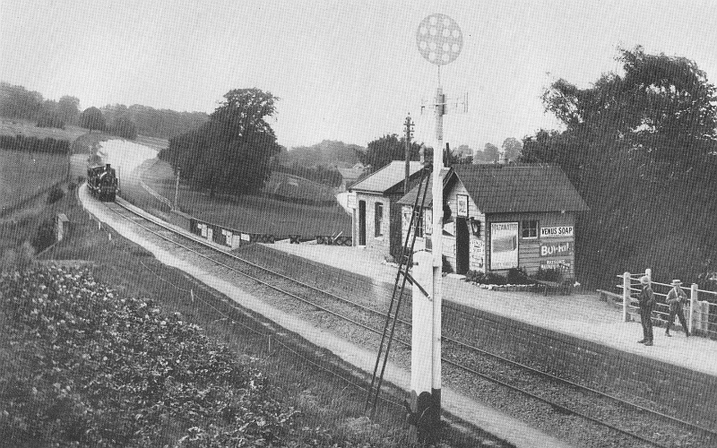
Spetisbury station looking north in the late 1890s
The DCR station at Spetisbury (spelt Spettisbury in some early S&DJR records) comprised simply a single platform on the Down side of the line with a timber-built waiting room and a separate booking office. Minute 3638 for the S&DJR Officers' meeting on 31-July-1888 (National Archives file RAIL626/16) records approval to extend the platform (at the south end) and provide a ladies' waiting room (constructed in brick adjacent to the original buildings) at an estimated total cost of £94. A good view of the station in that form can be seen in the photograph above, which probably was taken circa-1899 as the fresh chalk face of the cutting in the background suggests that work had started on doubling the line. Immediately north of the platform the line crossed Bridge 213 over a minor road, while public access to the station was by a steep path from the nearby main road up to the rear of the platform.
 The
earliest known record about signalling at Spetisbury is Minute 388 for the S&DJR Officers'
meeting on 8-November-1876, which stated that signals were to be worked from the platform
and it was to be a block post at a cost of £60. However this entry was
amended in Minute 398 of the subsequent meeting on 8-December-1876 to
state that it was NOT to be a block post. Visible
in the photograph above at the Blandford (north) end of the platform are two levers, which
are assumed to have worked the two stop signals provided (there is no evidence of any levers for distant
signals).
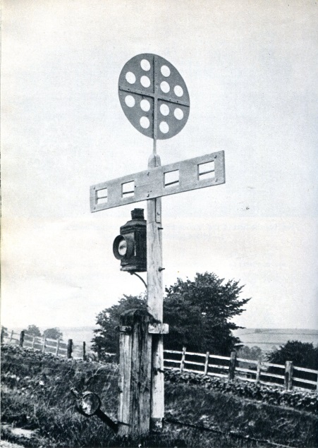
Directly opposite the platform was a disc-and-crossbar
(D&C) signal, one of the last
few to remain in use on
the S&DJR; there had been another D&C signal some distance up the line, situated on the Up
side of the line high on the side of the cutting (presumably for ease of
sighting by Down trains), but that was
replaced by a semaphore signal at an unknown date prior to 1901.
The
earliest known record about signalling at Spetisbury is Minute 388 for the S&DJR Officers'
meeting on 8-November-1876, which stated that signals were to be worked from the platform
and it was to be a block post at a cost of £60. However this entry was
amended in Minute 398 of the subsequent meeting on 8-December-1876 to
state that it was NOT to be a block post. Visible
in the photograph above at the Blandford (north) end of the platform are two levers, which
are assumed to have worked the two stop signals provided (there is no evidence of any levers for distant
signals).
Directly opposite the platform was a disc-and-crossbar
(D&C) signal, one of the last
few to remain in use on
the S&DJR; there had been another D&C signal some distance up the line, situated on the Up
side of the line high on the side of the cutting (presumably for ease of
sighting by Down trains), but that was
replaced by a semaphore signal at an unknown date prior to 1901.
The next available signalling reference is S&DJR Working Timetable Table (WTT) Appendix 7 dated 1-March-1886, in which Spetisbury appears in the "List of Telegraph Stations & Signal Posts" as open "7.30am until last passenger train" on weekdays. The location is not listed as being on a 'speaking telegraph' circuit and it is uncertain whether the reference was to a signal-box or the station office. It continued to appear in subsequent lists, although by 1905 the opening time was given as 7.35am and only the station office was listed specifically on a telephone circuit. It is unclear therefore whether the original station was ever a signalling block-post during single-line days, although that would appear to be unlikely.
The Electric Train Tablet (ETT) method of single-line control was introduced by the S&DJR between Blandford and Bailey Gate on 4-November-1886 and thereafter the signals at Spetisbury were used only for 'request stop' purposes. S&DJR WTT Appendix 9 dated 1-February-1889 stated:
"The normal position of the Signals ... must be at the "Off" position, except when required to be used to stop a Train which is marked to call by Signal only, or to protect any impediment or obstruction which may be on the Line, in accordance with Rule 157 of the Committee's Book of Rules and Regulations. In accordance with this Rule, when a Train has stopped at the Station, the Signals in both directions must be placed at "Danger", and remain so until the Train has again started, and has passed out of sight."
In 1899 work began to widen the trackbed between Blandford and Bailey Gate in readiness for a second set of rails, at an estimated cost of £35,000. The Parish Council petitioned for the station to be moved to a more convenient location to allow for a goods siding, but this request was refused. At Spetisbury the extra (Up) line was added on the west side of the existing single line, which was retained as the future Down line. Photographic evidence suggests that, as part of this work, the D&C signal at the station was moved temporarily to a new location adjacent to the Up side boundary fence, as it stood in the way of the new Up line. The existing platform was lengthened (again) and a new Up platform 300' long was added, together with a brick-built booking office and waiting rooms. Steps were built to access the new platform from the lane below and a foot crossing was provided to allow passengers to cross from one platform to the other. According to S&DJR Signal Instruction 139 the D&C signals were removed on 16-April-1901 (and presumably the platform hand-levers were abolished at the same time) and then on 29-April-1901 (Signal Instruction 140) the new double-track was brought into use, together with the new semaphore signals described below.
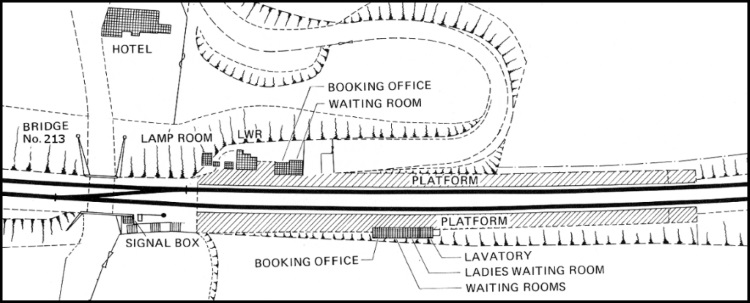
A 1923 Southern Railway plan of Spetisbury station
In connection with the doubling work a new ground-level signal-box was provided at Spetisbury, which was situated on the Up side of the line immediately next to the south (station) end of the parapet of Bridge 213. There are no known close-up photographs of this box, but from contemporary pictures of the station it appears to have been to the S&DJR Type 2 design, which is curious as the S&DJR Type 3 style had been in use since about 1895. It is probable that the official opening date for the signal-box was 29-April-1901 (when the sempahore signals were brought into use), but this can not be confirmed because no copy of Signal Instruction 140 appears to have survived. Spetisbury now became a block-post; ETT working between Blandford and Bailey Gate was abolished and replaced by normal double-track Absolute Block working on the two new sections Blandford - Spetisbury - Bailey Gate, probably using the standard S&DJR block telegraph instruments.
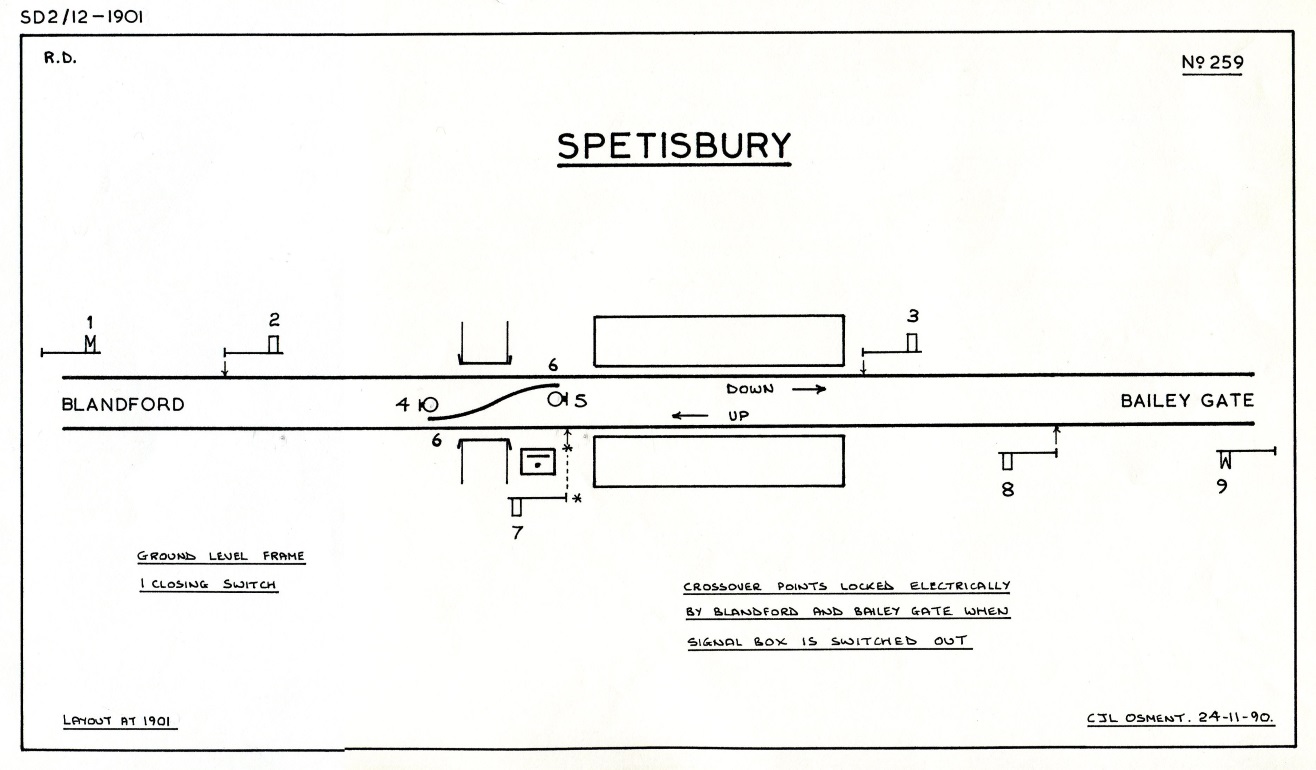
The new layout at Spetisbury was very simple and consisted merely of the Up and Down lines with a single crossover between them (located on top of Bridge 213). The S&DJR 1901 signal diagram shows that Distant, Home and Starting signals were provided in both directions and two shunt signals for the crossover. (Note: the signal diagram for Spetisbury in "An Historical Survey of the Somerset & Dorset Railway" [Ref 1] is incorrect as the functions of levers 5 & 6 have been reversed.) The signal-box was equipped with a 9-lever ground-level lever-frame which was probably of the Stevens & Sons 'knee' pattern (see note below), especially as a later visitor [Ref 2] noted that it was the version with weighted levers at each of the frame (for the Distant signals) which pulled down much closer to the floor than the remainder. However it is not known if the lever-frame received the modification to limit the stroke of the end levers and convert them to the 'normal' pattern.
[Note: the L&SWR/S&DJR obtained lever-frames made to the Stevens & Sons 'knee' pattern from a number of other manufacturers (or sometimes made them up from spare parts). Excavations at Spetisbury in 2018 revealed some metalwork adjacent to the former signal-box which bore the name of the Railway & General Engineering Co Ltd of Nottingham, who are known to have supplied at least one 'knee' frame to the S&DJR in the early 1900s, so one may speculate that perhaps that Company also made the lever-frame for Spetisbury.]
 |
|
|||||||||||||||||||||||||||||||||||||||||
| Spetisbury Signal Diagram 1901 Click diagram for larger image |
Spetisbury Mechanical Locking Table 1901 |
Although the new signal-box was a block-post and could have been useful to break the otherwise long block section of 6 miles between Blandford and Bailey Gate, it seems to have had little regular use. The earliest reference to the box is in the 1905 S&DJR WTT Appendix, in which it is listed as being switched-out "always, unless specially advised". The relevant Local Instructions in that Appendix stated:
"The Signals at Spetisbury will be worked only for Trains stopping at the Station, except on special occasions, when it will be opened as a Block Section, of which due notice will be given, as the ordinary Block Section will be as between Blandford and Bailey Gate. The Cross-over Road must not be used except whilst the Station is open as a Block Post."
It is not clear whether this meant that the signals would be put to danger behind every train stopping at the station, or that normally they would be left 'off' and only put to 'on' for 'request stop' purposes. Similar local instructions were contained in the 1914 S&DJR WTT Appendix. Photographic evidence shows that at least some of the main running signals were of lattice-post construction with full-length sighting boards down the front, although the boards were removed in later years; the shunt signals were probably of the Stevens 'flap' type, but this has not been proven. Click here for further general information about S&DJR signals.
A curious feature of the 1901 signalling installation was that, when Spetisbury signal-box was switched-out, the crossover points were locked electrically by the adjacent signal-boxes at Blandford and Bailey Gate. It is not known if this arrangement was unique, but it was very unusual and there seems to have been no obvious reason for it; no other similar installation is known on the S&DJR. The following is the text of the relevant Special Instructions notice that was displayed in the signal-box:-
|
South Western and Midland Railway Companies SOMERSET AND DORSET JOINT LINE INSTRUCTIONS to be OBSERVED by the SIGNALMEN on DUTY at BLANDFORD, SPETISBURY and BAILEY GATE when SPETISBURY STATION is being OPENED and CLOSED as a BLOCK SECTION. 1. Before opening Spetisbury as a Block Section the following instructions must be carried out, viz:- The Signalman at Spetisbury must ascertain by enquiry from Bailey Gate on the Telephone whether there are any trains in Block, either on the up or down line, and if there are none, he must place all his fixed signals to Danger, and then give the Opening of Signal Box Bell signal on the Special Bell circuit to the Signalman at Blandford, who, after satisfying himself that the Block Sections between Blandford and Bailey Gate are clear and the Block Indicators are in their normal position, will repeat this signal. 2. The Signalman at Spetisbury must then hold over the Sykes releasing Switch to the left for several seconds, and until Sykes Instrument is released. 3. The Signalman at Blandford after having received the Opening Signal from Spetisbury on the Special Bell circuit, will pass the Signal forward on the Ordinary Bell circuit to Bailey Gate. The Signalman at Bailey Gate after repeating the same, will press down his Bell key and keep it down for 10 seconds. 4. The Signalman at Blandford directly he has received a repetition of the Opening signal from Bailey Gate, will press in his special plunger and keep it pressed in for 10 seconds. This will cause the Sykes instrument at Spetisbury to be freed, and at the same time to slide the Day and Night Switch Bar to the In position, and release the locking of the Cross-over lever; when this has been done the Testing signal must then be forwarded on the Ordinary Bell and Block circuits by the Signalman at Spetisbury to Bailey Gate and Blandford respectively, and the repetition of these signals will indicate that the Bell and Instruments are in proper working order, and the Opening arrangements will then be completed. 5. To close the Spetisbury Signal Box the Signalman at Spetisbury must take care that there are no trains in Block and that the Block Indicators are in their "Normal" position, he will then give the Closing of Signal-box Bell signal to Blandford and Bailey Gate, and directly afterwards pull over the Sykes small locking lever in front of the Signal frame, which will complete the operation. The fixed Signals must then be taken off, and all lights (except those required to be kept burning) extinguished, and all windows and doors secured, as laid down in Rule No 24 of the Double Line Block Telegraph Regulations, and in case of any failure of the Indicators or Bells until the instructions contained therein have been carried out. GEORGE H. EYRE, Offices, Midland Station, Bath, April 1914. |
It is interesting to note from these Instructions that the signalman at Blandford had to send an 'opening signal-box' bell code to Bailey Gate for a signal-box other than his own. Although the special locking was mentioned on the original 1901 signal-box diagram the original copy of these Instructions bears an issue date of April 1914, which perhaps reflects a re-issue for some reason. It is assumed that these arrangements ceased upon the subsequent removal of the crossover, but that is not confirmed.
Recent research has unearthed information which, although not related directly to Spetisbury nor the S&DJR, may throw some light on the background and operation of the switching in/out process. The L&SWR used a number of methods for controlling ground-frames (GF) at intermediate sidings in double-line block sections, including the situation where a crossover existed between the Up and Down running lines, in which case the GF would have signals on both lines and a block-switch. The GF would normally be switched 'out' as a block post with all its signals 'off', but in order to work the intermediate siding the GF would be unlocked by the next signal-box along the line, the signals put back 'on' and the block switch turned to 'in'. If one ignores the absence of a siding, then the basic method of controlling such a GF appears to match the arrangements at Spetisbury with only minor differences.
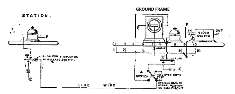
The diagram above shows a 'typical' Sykes circuit for the control of an intermediate GF with crossover and signals; in this case the 'station' would be Blandford and the 'ground frame' would be Spetisbury. In the 'typical' scenario all the signal levers would be locked in the reverse position when the GF was closed, but at Spetisbury it was only the crossover points lever (6) which was locked (the original S&DJR signal-box diagram was annotated that all the signal levers were 'free' of the switching controls). The Sykes instrument would appear to be a normal 'Indicator Lock' instrument working a 'front lock' on lever 6 with linkage to the block-switch, except that it was reset manually by the signalman rather than by means of a cam on lever 6. It is probable that the aperture in the instrument displayed 'LOCKED' when Spetisbury was switched 'out' and 'FREE' when switched 'in'.
The reference at (5) in the Special Instructions about the use of the "Sykes small locking lever in front of the Signal frame" when switching 'out' suggests that at Spetisbury the lock-blade may have been lifted by pulling a small lever (possibly adjacent to the instrument) rather than by means of a handle attached to the down-rod as shown in the diagram. 'Switch A' is mentioned in the Electrical Locking table of the S&DJR signal-box diagram and is presumed to be the "Sykes releasing Switch" mentioned at (2) in the Special Instructions; it is probable that this was a rotary switch which was spring-biased to its normal position and had to be held over by the signalman until the release had been completed. It will be noted from items (3) and (4) of the Special Instructions that a release plunge was required from Bailey Gate as well as Blandford when switching 'in', which probably involved modified circuitry at Blandford in the feed to the Line Wire to Switch A at Spetisbury.
Please Note that the foregoing details about the Sykes circuit are purely speculative and, in the absence of any definitive information, are included here simply as a 'best guess' guide to how the switching in/out process may have been implemented in practice. Exactly why the S&DJR chose to implement this type of control at Spetisbury remains a mystery.
In 1922 the Redhead Commission reported on possible cost-cutting measures throughout the S&DJR system. At Spetisbury expenses were up by 395% and it was recommended that the station master be made redundant, saving £200 per year; his duties were undertaken thereafter by the Blandford station master. Subsequently the station became unstaffed with effect from 13-August-1934 and then became a Halt, although some sources quote 1-January-1939 as the date for reduction to Halt status, and the timber buildings were probably demolished around the same time.
At the S&DJR Officers Conference on 23-January-1918 it was reported (Minute 6993) that the cross-over road at Spetisbury was not required and it was agreed to recommend that it should be taken out; this would give an annual saving of about £5 in maintenance and £11 in renewals. Exactly when this work was done is unclear, as the cross-over was included in the subsequent SR 1923 plan, but it was omitted in a 1930 'office copy' of the signal-box diagram. In one of the S&D "Fortnightly Notices" for late 1948 it was stated that Spetisbury signal-box would be opened as a block-post (ie 'switched in') on 5-January-1949 (presumably just for the one day) to allow the cleaning and overhauling of the mechanical locking. It may be that event which drew attention to the state of the signalling installation, because in due course in a BR(SR) letter of 1952 it was noted:-
"The condition of the locking-frame and much of the signalling apparatus at Spetisbury is worn out. Also the box structure is in need of considerable renewal. It has not been found necessary to open the box for a number of years and there is no apparent reason to anticipate such a course being necessary in the foreseeable future. In the circumstances it is recommended.....the box to be abolished."
The following costings were given in support of the closure proposal:-
| Civil Engineer |
S&T Engineer |
Total | |||
| Original cost | £36 | £414 | £450 | ||
| Present renewal cost | £180 | £1449 | £1629 | ||
| Gross removal cost | £28 | £127 | £155 | ||
| Recoverable material value | £2 | £64 | £66 | ||
| Net removal cost | £26 | £63 | £89 | ||
| Annual maintenance saving | £1-10-0 | £27 | £28-10-0 | ||
| Commuted renewal sum saving | £0-10-0 | £10 | £10-10-0 |
One may wonder why so much repair would seem to be necessary to a signal-box that apparently had received so little use. The signal-box was closed on 10-August-1952 and the station itself was closed on 17-September-1956, the remaining buildings being demolished sometime afterwards. It is curious therefore that there is a photograph of the station on page 84 of "An Historical Survey of the Somerset & Dorset Railway" [Ref 1] which shows the signal-box and the Up Starting signal (7) with its arm in the 'off' position, yet is dated 1961; that date probably is incorrect, as a BR(SR) notice confirms the date for abolition of the box and signals. It is certain that the signal-box and station buildings had been demolished by 1963.
Postscript...
On 6-March-1966 passenger services ceased on the whole of the S&DJR. Although most of the line closed at the same time, a few sections remained open for goods traffic and this included the line through Spetisbury from Broadstone as far north as Blandford. During 1966 the Up line was taken out of use and the Down line was worked thereafter as a siding for traffic in both directions. Eventually however the last remnant of the old S&DJR line in Dorset was closed on 6-January-1969 and the track through Spetisbury was lifted in April 1970.
In the mid-1990s Dorset County Council established a path along the trackbed for walkers, cyclists and horse-riders, and today this forms part of the North Dorset Trailway. Subsequently in May 2012 a group of volunteers, working under licence from Dorset County Council, began to clear the station site with a view to eventual restoration as part of the Spetisbury Station Project and this work is continuing.
© CJL Osment 1999-2021
Acknowledgements to the late Denis Cullum and Malcolm Trigg for the loan of relevant material,
also the
Blandford Forum Railway Club and
Spetisbury Station Project for archive material.
References
|
© West Country Railway Archives 2000 Page last updated: 16 February 2021 |
URL: http://www.railwest.org.uk E-Mail: railwest@bigfoot.com |
||||||


