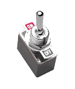
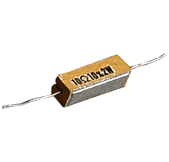
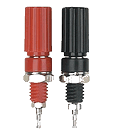
All of the parts for the "conversion" can be purchased at Radio Shack or any electronics supply. The main parts are terminal posts (6), a SPST On/Off toggle switch and a 10 Watt 10 ohm wire wound resistor (ceramic case)
A Versatile and Hefty Power Supply for Your Model Railroad
Model railroads need power not only for the locomotives but also for the accessories that make the railroad more realistic and fun to operate and watch. These "accessories" include switch machines for remotely controlled switches (Often called "turnouts" by modelers.), lights for buildings and control panels, and sometimes to power electronic gizmos like block detectors, signals or sound generators.
Sometimes this extra power, which may be AC or DC, is supplied by old MRR power packs or "wall wart" power supplies. It recently came to my attention that an old PC power supply (PS) could be converted to a cheap and powerful supply for multiple voltages. One of my Atlas Forum friends, Bill, sent me an ATX PC power supply and some information on how to use the various voltage outputs.
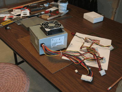
The instruction sheets that you see in the photos are from the link with the details of this project.
Wire wound resistor - 10 Watts 10 OHM
Part # 271-132
SPST Toggle
Part # 275-602
Binding Posts
Part # 274-622
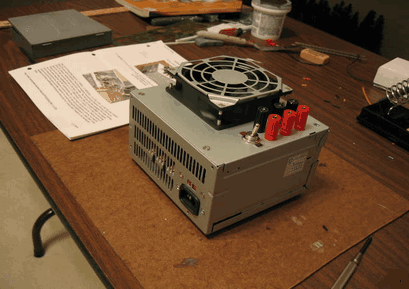
This third photo shows the desk-top or shelf-top version after modifications.
Note the load resistor has been attached to the inside of the case against the "grill" with wire ties. Heat sink compound was also used to give the resistor maximum cooling as indicated in the link that has been referred to. This works very well and the unit runs quietly and cool.
You can also see the new On/Of switch. Stick-on rubber "feet" have been added to the bottom of the unit to keep it from sliding. It will be mounted on a small shelf under the layout and 14GA wires from the terminals will feed distribution terminal blocks from whence the appropriate voltages will be neatly routed to the devices around the layout.
The unaltered ATX PC PS looks like the photo above (Please excuse the mess.). Note the many wires and plugs that supply many different types of voltages to standard PC components.
Also be aware that these power supplies don't have an external mechanical On/Off switch and that they must detect a "load" before they will turn on. They are pretty complicated gizmos for the likes of me. I just wanted a power supply that I could easily hook to devices on my layout and turn on and off at will for safety.
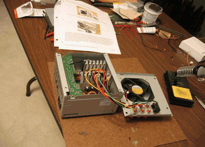
The photo below shows the PS after all of the unnecessary wires have been clipped and the appropriate wires added to the new post terminals on the PS cover plate. The orange wires are 3.3VDC. The red wires are 5VDC and the yellow wires are 12VDC. There are a lot of each but you just need to keep one each of the orange and yellow and two red wires and 5 black wires. Also keep the green wire as it is the on/off signal wire. The rest can be clipped at the circuit board. I removed the circuit board for access to the wires and to attach the load resistor to the grill.
But I struggled with exactly how to best modify the PC PS so that the different voltages could be easily used and neatly distributed around the layout. Then Bill sent me a link that clearly described a very orderly way to convert a PC PS to a desktop PS for lab use (See the links page for more information.)
Copyrightę 2001 - 2013 Jack W. Murray, Jr.
All rights reserved
Wiring Summary: I connected each of the red post terminals to an orange, red and yellow wire respectively and I provided a separate black ground post (black wire) for each voltage. Separate ground posts are not necessary but seemed "tidy" to me.
The load resistor is connected between a red and black (5VDC) wire with heat-shrink tubing at the connections since the resistor leads were long bare wires. The resistor is attached to the "grill" with wire ties as shown above.
The On/Off SPST toggle is connected across the green and black wire. Grounding the green wire gives the circuit the signal to power on if there is a load (The resistor.)
Please be sure to refer to the original link for more complete detail. You can build several variations on this power supply, even providing terminals for + and - voltages.
