Tips & Tricks
Gluing N-Scale:
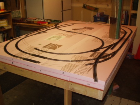
The switch to or addition of an N-Scale train layout was a plan that took many years. I held off the plan because I was learning so much with HO that I thought I wasn’t ready. Jay and I went to several show and visited local enthusiasts that in total convinced me to get to work. I tried to remember to take pictures at every turn for my benefit mainly. Now I felt pretty smart with the things I learned with the HO build, however I have been humbled at almost every step of the N scale! I started with a different frame work for the table and chose “floor underlayment” for the surface. Great smooth surface to work on but really brittle and support was a must. Then I chose a foam road bed over cork just to try something new, again I was schooled! I learned the use of different glues some expensive and some cheap. In my opinion I didn’t see much difference in white glues for the foam road bed. I used a craft tack glue from Wal-Mart (about $4), “Mod Podge” sealer glue from Michaels’ (about $6) and “Foam Tack Glue” from Woodland Scenic ($10), All seamed to work about the same but I chose to finish with the Woodland Scenic glue because it was the most expensive and I wanted to get my money’s worth out of it. For the wood I prefer “Elmer’s” yellow wood glue. I have used this for years and I am really happy with the outcome. I did a bit of research on securing the track to the road bed and ended up with nails… wait before you scream at me I didn’t use them, I was told to look a bit harder and research gluing the track down. I was hesitant because I didn’t think it would work, no mechanical fasteners would leave it to fail! After hours of reading I was sold. I tried three different types of glue I read about and the results were much different than gluing the roadbed! The “Foam Tack Glue” from Woodland Scenic I used for the roadbed was also recommended for the track. I tried it on a few pieces and liked the outcome but the application was slow and not real user friendly when you are picky about the waste. The craft glue mentioned earlier was tried and didn’t hold up to my pry test so I moved to Red Devil 100% Silicone (clear) with the tip cut close to the end for a small 1/8” hole at an angle. Got to say I was skeptical again but it really worked great. The silicone was sturdy to my pry test, flexible to hand pressure and cures almost invisible to the eye. Little glossy but ballast will cover it. If you plan accordingly you can even add ballast at the same time. I didn’t plan that far ahead. And this is were I am at!
Weathering the Roundhouse (Undercoat):
The technique is different than what we use for track Accept the wet sponge and
Weathering always seems to be a daunting task but once started it has a life of its own it seems. A few things that I have learned is that when you initially look at the end product you may think you have gon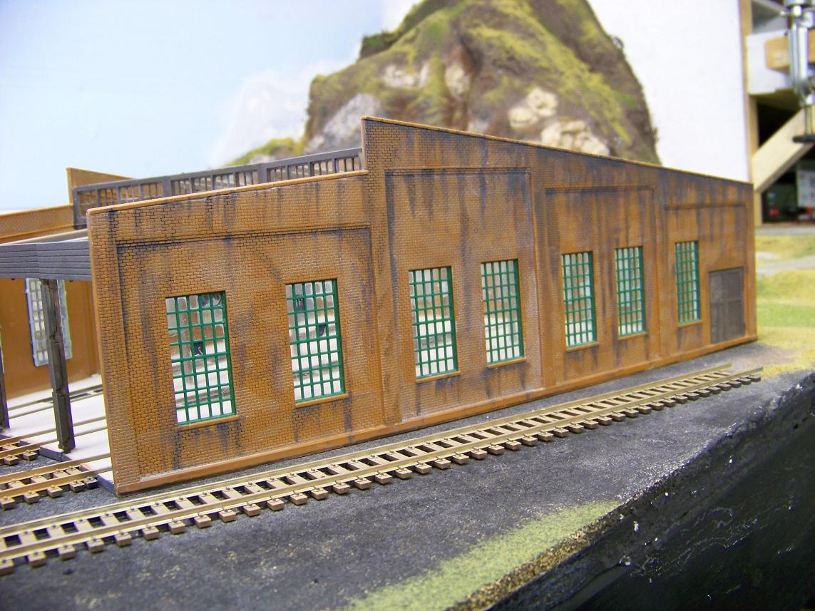 e too far. That has not seemed to be the case for me. Once I step back from it and look at it from the big picture side it blends very well. I have been using very simple techniques to get the effects that I have been looking for. There are two layers of the effects that I have been working one. The first is the undercoat and the last … you guessed it is the overcoat. My undercoat is mainly to give some definition to the bricks and mortar. As most building do not run the same color as the bricks from the foundation to the roofline. I accomplish this by using a wash of gray with a little water to thin it a bit. The thinning of the paint allows it to flow into the spaces between the bricks more effectively. I am not concerned about getting the wash on top of the bricks because the will help in causing the bricks not to all hold a uniform coloring. I work in small areas dabbing the brush in the mortar wash then onto the area I am starting with. I allow the wash to seep into the crevices and run down the structure toward the foundation. Doing this will also help give the illusion of the weather (i.e. rain) giving weathered
 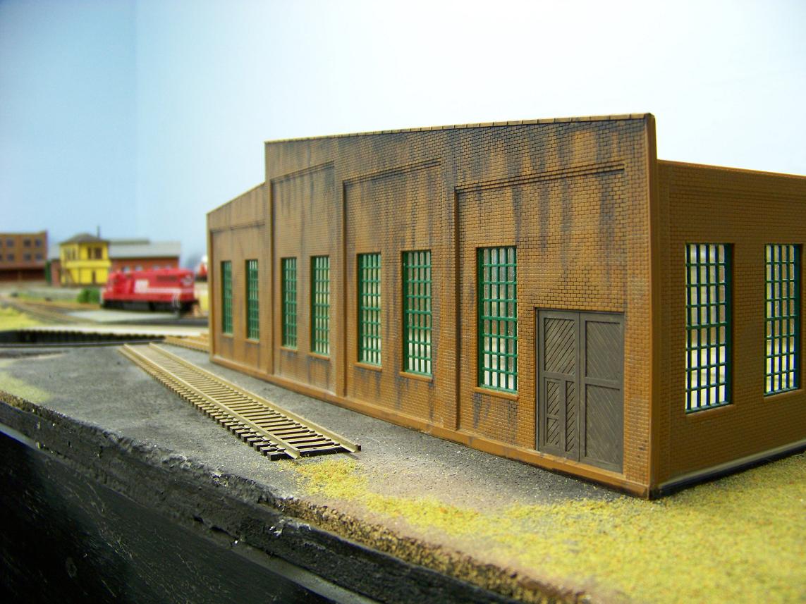 effects of the water running down with gravity. I will also use this technique on the next layer to wrap it all together. After I allow the paint wash to dry for a few moments I take a paper tower and wipe of most of all the paint leaving what is in the crevices and a slight film in places on top of the bricks. I may add multiple coats to the area depending on how deep I wish the colors to be. Remember everything in nature is not uniform so not every brick, crevice and line needs to be painted. I usually will work on one side of a structure using this method before moving to the overcoat. I do not necessarily let the paint dry between layers as the wash is thin and will dry quickly and if it isn’t then the paint of the two layers will bleed together a little which will only help with the natural look of the structure. I will
Soldering wires under the layout:
The technique is different than what we use for track Accept the wet sponge and a good soldering tool… We fought with many different methods and ideas and found using an in-expensive alligator clamp set up,  helped tremendously when soldering wires in hard to get to areas under the table. We have even used it on the bench top to hold wires still.
First, ensure you use flux, either in the core of the solder or applied before soldering. This aids the solder flow into the joint of the two items being soldered.
Second, it helps to know how well your soldering iron heats and how fast it heats metal. I load up the wire first by placing the iron on one side of the striped wire end and apply solder to the other, within seconds the solder flows into the wire strands. I apply a little extra because as I will explain it make joining ends much easier.
Last, we use the alligator clamp stand basically to hold the wires close together so they don’t move and you don’t burn your hands; of course we switched to this after I toasted my fingers over and over! It works like a second set of hands. Make sure they don’t pinch through the wire sheathing. Some of the alligator clamps are strong and sharp, you may consider a couple wraps of tape or carefully bending the teeth over. Once you position the wires were the touch and overlap just hold the soldering iron to the joint and the excess solder placed there before quickly forms a solid joint (this is what the little extra is for). We found loading the wire ends before running the wires also helped with the ends staying straight as well as quickly joining. I have seen several layouts that they used solderless wire caps, I prefer the clean look of the overlap end joints.
Installing Rotary Beacon on Athearn SD60:
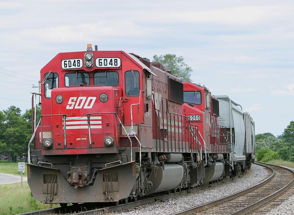 As I was trying to determine just how best to remove the cab of my GP38-2 to install the beacon by gaze shifted over to my SD60 #6048 waiting patiently on the track. How difficult can it be I thought. Well it really wasn't that bad once all saw said and done. I put my GP38 to the side for a bit and began working on my SD60. By the end of the evening I had the beacon install and operating. After removing the shell from the frame I also disconnected the forward and reverse head lights. Removing the front ones mad the placement and installation of the LED just that
 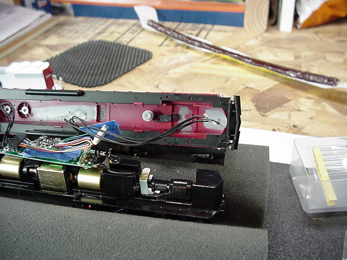 much easier. after marking the shell where I wanted to drill my holes I used my fingers as a manual drill and drilled the two holes needed for the legs of the LED. I test fit the LED and was pretty happy on how it turn out. The one thing I will remember in the future is to drill the holes on the inside of the mark as I have one hole that is visible slightly from under the beacon. I will try and get a picture to show that. Next I took some SOO Line Red and painted the base and bottom lip of the LED to give the impression of a housing for the LED. Reinstalling the LED after the paint dried I soldered the resistor (which I snipped a portion of the legs from the resistor to give it a smalle
 r foot print) to the green lead which is the lead for Output C on my Lenz decoder. I also soldered a wire to the other lead of the LED and connected it to the common side of the front headlight. After testing the operation I covered the two legs with heat shrink to ensure no shorting. I replaced the headlights and used hot glue to hold them and the LED in place. Now I have a SD60 with the detail of a rotary beacon that will flash using function 1 on my Digitrax controller.
Installing Rotary Beacon on Atlas Trainman GP38-2:
I am starting my first adventure in detailing an engine. 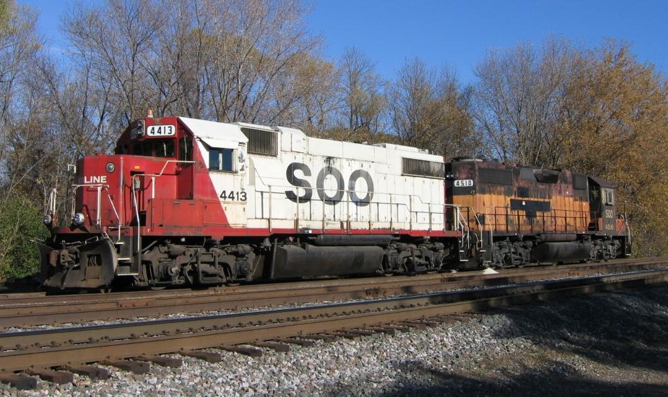 I am starting with my SOO GP38-2 with the road number of 4413. Just as the first line of "Painting bas color", start with a plan. I did a lot of research to find just the correct LED for this project. I was looking for an amber beacon that I could program with DCC to strobe. The LED that I found was from the website www.moreleds.com. I contacted them and recieved a response back quickly.
 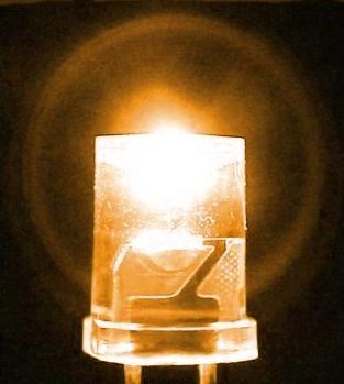 The person that contacted me was very helpful and aided with my purchase. I purchased 20 3mm inverted cone LEDs in amber. The purchase also included the resistors needed for the project. And as a bonus the package contained an additional LED above what I had ordered. With the new parts in hand I made a journey to the train room. I wanted to test the light with the decoder first before drilling into my new engine. Using a Lenz Silver MP decoder, I first soldered the resistor to the long leg of the LED and soldered the violet lead from the decoder to the other leg of the LED. With the Lenz decoder, the
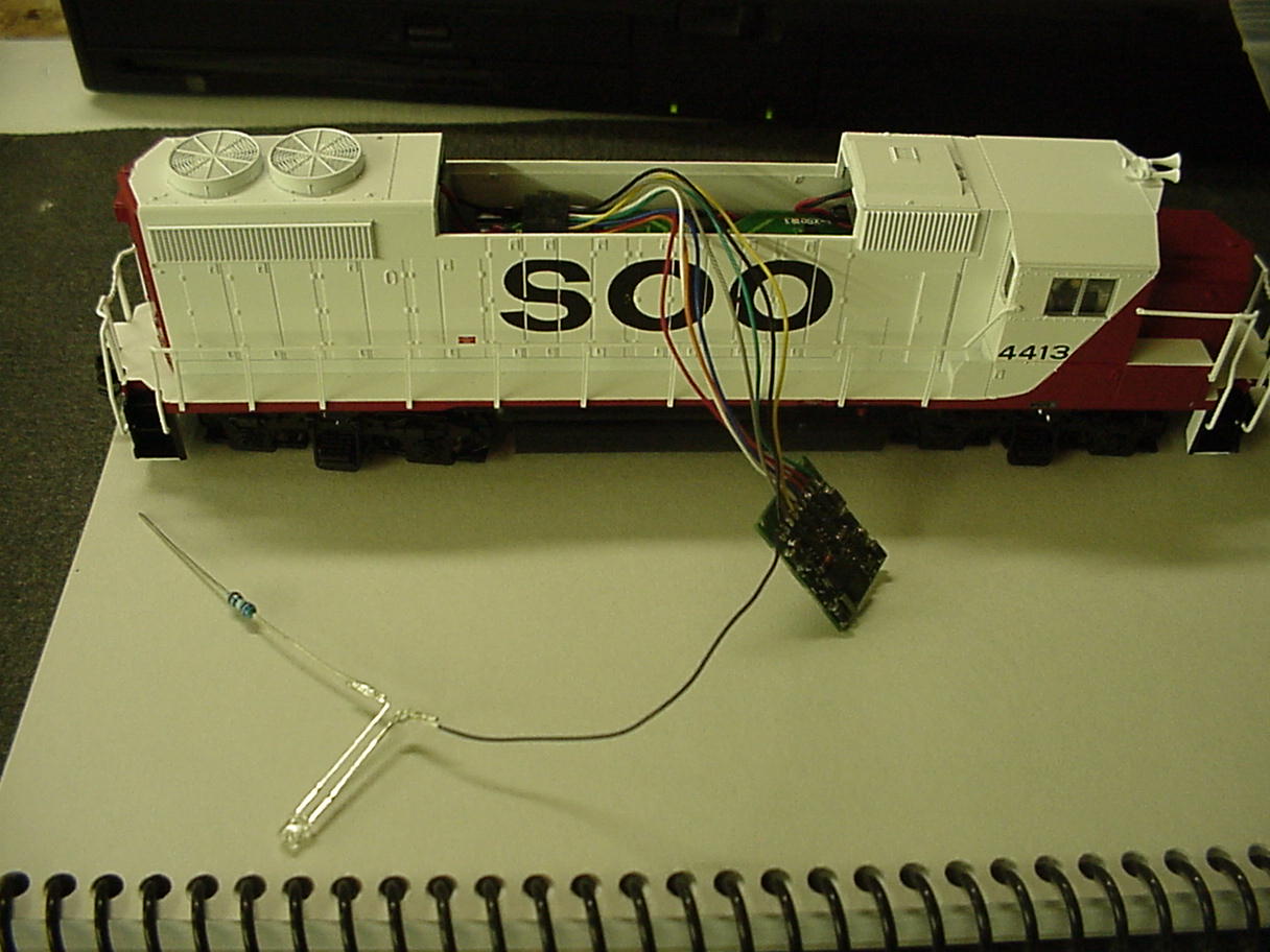 violet lead is designated for Output D. I only used Output D as the test. for the installation I will wire the beacon to Output C (green wire) as I will have more control of the strobe and will leave Output D for the ditch lights (a future project). I used Decoder Pro to program how I wished the functions to operation. Connecting the resistor to the Blue wire (common wire) I was pleased to watch the LED strobe or flash like I wished. Next in the process is drilling through the rood and securing this LED. That is my task for the weekend. See you soon with chapter two!
Painting base color:
As always start with a plan, it can changes as most of ours have to some degree but have an idea before you start. We painted the surface a base color for uniformity just in case scenery didn’t cover; it also helped our vision of what we wanted to end up with. We used acrylic art paint found at just about any art supply isle or store you visit (inexpensive too). We found that an airbrush works great if you don’t have scenery to protect from overspray and you dilute it 60:40 water to paint. It is easy to cover large areas however it provides a uniform color once dry unless you plan specific alterations to provide depth or texture or alter paint mixes with different shades, we chose the later. I found it easier to start with the lightest colored areas for high points and edges then slowly add darker tones to create depth in the shallows when needed. This holds true when brushing paint on too. I chose a ½” brush to control texture, takes longer to cover the area but I prefer the control of the smaller brush. I alternate my grip side to side and rotate the brush slightly in my fingers to prevent a repeat pattern in the paint (If anyone remembers Bob Ross, Joy of painting. He was corny but really good and explained everything he did as he did it). By adding small drops of paint as you go and alternating color/tint you can simulate earth tone changes well. I was really surprised how much grey everything has as a shade, it works like a bit of yellow does to accent sunlight on plant material. By lightly airbrushing grey over green/brown on the edges of a dirt road you can simulate dusting from the traffic. We also airbrushed the ballast tone on the cork road bed before applying it to ensure even color distribution (check out pics page).
Soldering Track:
The technique we now use is similar to what we started with, just faster. The first tip is having a good soldering tool! Second have a damp sponge; I can’t emphasize those two enough. Once I started… with the plan, I worked from left to right (I am right handed), you don’t want to rest you arm on freshly soldered track. I learned early on don’t apply solder on the inside of the track unless you plan to remove it for wheel travel. I place the soldering tool on the inside of the track in the middle to near the top edge to prevent heat travel to far into the ties (see out “Found the Short” problem in the blog page). For our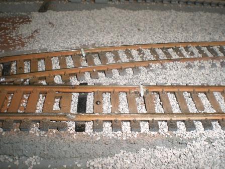 soldering tool it only takes about 10 to 12 seconds to heat enough for the solder to melt on the outside of the track just over the track connector. I ensure the solder runs the full length of the connector and into the track joint. Another concern I ran into is how tight the track connector is, some were loose and I had to control the rail height with the soldering tool as the solder was applied till it was cool. Once it flows in remove the tool and blot with the sponge to draw out the heat, carefully because you can disrupt the solder with the sponge. The next tip we learned unfortunately by error; TEST the track before you get too far, I would check every few feet or three solder joints. We didn’t and I created a short we think from over heating and it took two days to find and we had to pull up several feet of track. Once soldered I used a jewelers flat file to knock off the small bump on the top of the track, after I got the flow right I just used an abrasive track erasure to remove the flux. You will need to watch for stray solder pieces hiding under the track and look for good coverage on the joint before you move on.
Casting finishes:
A previous article written on casting with resin describes how to cast resin but I wanted to add a bit of the color aspect… First as always have a plan or idea. After the castings are secured/glued/attached we started coloring rock and brick with a base of white Gesso (paint canvas primer) then black or dark grey tempura powder (Ours came from Bragdon Enterprises. See our “Tried & True” links page) but you can use what you prefer. I used a 2” brush to apply the dry powder, dip the brush in the powder very lightly it goes a long way. Apply it over the dry repeat dry Gesso, ensure you get it into all the cracks and crevices as well as the rest of the casting then lightly spray water over the casting, and use a damp sponge to wipe it around/off this will set the color and create highlights were it gets wiped off. If for some reason you screw up or don’t like the shadowing just re-primer it with Gesso and start over just make sure you brush on the primer thinly to keep detail in the casting. Take your time this is an important step in creating depth. Picking weathering colors depends on your layout; ours is set in darker dirt so less yellows and tans and more grays and browns. Bragdon has great directions if you want more in-depth guidance. They have set us up well after the demo we sat through, again if you get the chance to see his demo GO!
Geodesic Foam update ...
We had received an email from Joel at Bragdon Enterprises and he left these tips for using his product.
"Your review was very nice and so was the project. Here are a couple of tips. I have found that the low temp hot glue is not nearly as strong as the regular purpose material. If it gets fairly warm it really begins to soften. This could be an issue with modules being transported in hot weather. I use the hotter glue and always wear cheap disposable gloves and often a long sleeved t-shirt to protect my arms from hot glue drips. Also, when casting large molds (any mold over about 1 1/2 sq ft) I wear the same cheap gloves to distribute the Cast Satin and foam resins onto the molds instead of the home-made brushes. Quick and efficient, works great. Restaurant and food service stores seem to have the best prices on disposable gloves." Joel Bragdon, 8/14/07
DCC setup ...
When we started our model railroading 3 years ago we had started with a DC controller. That lasted us about a week once we saw what DCC could do. Our first DCC purchase was the Bachmann E-Z Command Controller w/ Santa Fe DCC engine. We were amazed at what we could do with this. Since David was new to the hobby he was able to purchase newer engines and have DCC chips installed in them. I still had Athearn Blue Box engines from 15 years prior. I had one installed so I could learn how to install the chips within the engines. As 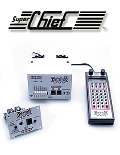 we gathered more engines and the layout grew it become obvious that our DCC needs were growing as well. With that we invested in the Digitrax Super Chief. now it may be said we had moved from one end of the spectrum to the other, but I knew we would want more of a system as we grew even more. Currently I have a test track and programming track wired upon my work bench. We have 3 UP5 Panels (data jacks) mounted on the layout. David has now purchased a UT4 Throttle so both of us could run trains at the same time. One of my feeling of wanting the Digitax was the DT400 Throttle. I wanted the ability to have quick control of two train at the same time.
A Ballasting we will go ...
So I started the adventure of ballasting and read many articles regarding the process. Through all of the articles the one constant that I did see was the mixture of the glue solution to set the ballast once it is in place. To obtain this solution, mix 1 part glue, 3 parts water and a few drops of detergent. Now even with the detergent added as an agent to allow the glue to seep into and around 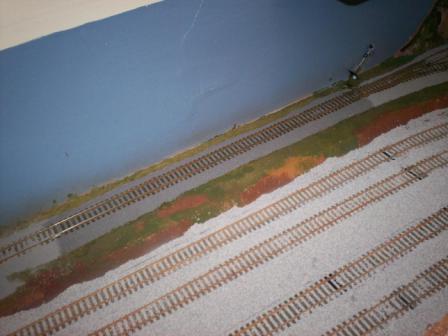 the ballast I still found the glue sometimes pooling on the top of the ballast. Remembering an article that I read, I altered my process and wetted the ballast with 70% isopropyl alcohol first and then added the glue to the ballast which works like a charm and the alcohol allows the glue to easily cover not only the top of the ballast but more importantly into the base of the ballast underneath. As I only now have about 4 feet of mainline track that I have ballasted, I am thinking of different ideas on how to make the process more efficient. First we designed, well a better way to say it David designed a ballast spreader and I think that laying some glue at the edge of the track then dusting it with ballast will give a cleaner edge to the ballast. These are two processes that I will explore once I begin the engine yard. For our mainline we are using Woodland Scenics fine gray ballast. One thing also to remember is that once glue is applied the ballast will become a darker shade of which ever color you use. I will go into more details of adding the ballast and spreading it with the methods I am using now so check back soon.
Geodesic Foam ...
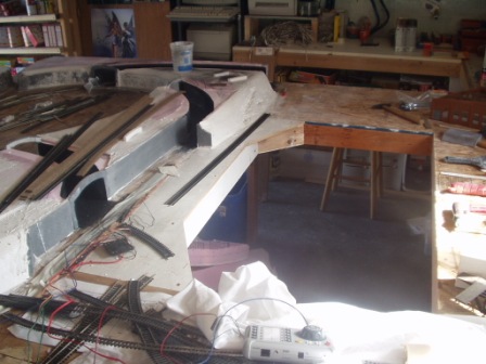
Most of our scenery structures are now built with cardboard, a hot glue gun, two part liquid foam similar to epoxy sandwiched between fiberglass screens, and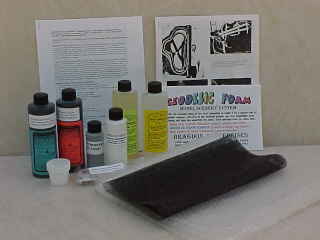 then covered with resin poured rocks and ground cover (See Links page for Bragdon Enterprises). We start with the “plan” and build a skeleton or frame to support the surface by gluing cardboard, we created a center line of the mountain and ran strips from that to the sides for shape and strength then glued a few pieces across those strips to tie it all together, cut your pieces of cardboard against the wave to help hold it rigid (check out our reviews of Geodesic Foam for more details of this process).
Using Plaster of Paris ...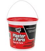
Foam Insulation (Do & Do Nots) ...


 plaster doesn’t allow changes and it, very brittle. We found it requires re-enforcements, either newspaper strips (1/4” wide) or wood strips (like toothpicks) when poured ½” to ¼” thick. When set it requires sealing because it soaks up primer and limits adhesion of latex paints. The plaster also adds weight to the layout and can be difficult to sculpt unless poured in detailed molds.
  insulation manufactured by Owen Corning (NOT Styrene “white” similar to Styrofoam cups, I’m referring to the insulation type foam), Tip number