


| Summary |
|||
| Basic Principles | Traction Current |
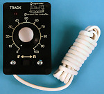
Walkaround | Distribution |
| Back to the RiTB main page |
|||
 |
|||

| 2 rails DC |
3 rails AC |
 |
|
| The
transformer T1 (Track) is connected to the 2 rails, and the transformer
T2 is connected to the catenary and to one of the rails (defined as the common rail to the two transformers). This allows independent control of 2 locomotives on the same section of track. |
The transformer is connected to the 2 rails (in short-circuit) and the catenary. |
| To switch between the2 systems, it needs: |
||
| 2 rails
DC |
3 rails
AC |
|
| Rail 1 |
DC Transformer
T1 (V) |
Ground |
| Rail 2 (Common) |
Ground |
Ground |
| Catenary |
DC Transformer T2 (C) |
AC Transformer T3 (C) |
| For the rest, I will use the abbreviations M ("Masse" in french, ground or common rail), V ("Voie" in french, the other rail) and C (Catenary) | ||
 |
 |
|
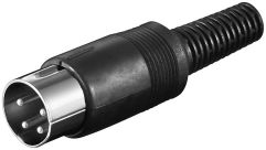
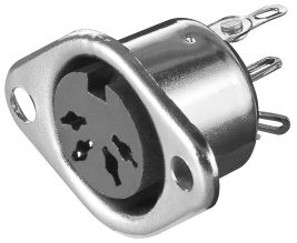
| 1- M ("Masse", traction ground) 2- V ("Voie", Rail) 3- C (Catenary) 4- T2 (DC Transformer T2 "Walkaround") 5- 14V accessories 6- Ground 14V |
|
| Each module
is equipped with a splitter (a simple bar of 12-pole dominoes) ensuring
the connection with the next module and to "stitch" the current everywhere
necessary. |
|
 |
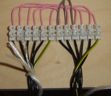 |
| The four cores M, T2, 14V ~ and 14V ~ M allow to install sockets wherever it
will be necessary for the connection of the walkaround. |
|
|
 |
 |
Retour au menu principal (Français) |
 |
Zurück zum Hauptmenu (Deutsch) |
 |
Back to the main index (English) |


