|
MISSOURI
PACIFIC EMD SD LOCOMOTIVES
|
|
The following
is reproduced from actual operating manuals
|
SD40
25 Units
Horsepower:
3000 Weight: 389,910 lbs.
Engine: 16-645E-3 V-Type Turbocharged
Fuel Capacity: 3,250 gals.
Gear Ratio: 62:15
Minimum Continuous Speed: 12.0 mph Cooling
Water Capacity: 254 gals. Tractive
Effort: 97,475 Sand Capacity:
56 cubic feet
Lube Oil Capacity: 243 gals.
SD40-2: 207
Units SD40-2c: 74 Units
Horsepower:
3000 Weight: 390,600 lbs.
Engine: 16-645E-3 V-Type Turbocharged
Fuel Capacity: 3,250 gals.
Gear Ratio: 62:15
Minimum Continuous Speed: 12.0 mph Cooling
Water Capacity: 275 gals. Tractive
Effort: 97,650 Sand Capacity:
56 cubic feet
Lube Oil Capacity: 243 gals.
SD50: 60
Units
Horsepower:
3600 Weight: 368,000 lbs.
Engine: 16-645F3B Turbocharged
Fuel Capacity: 4,500 gals.
Gear Ratio: 70:17
Minimum Continuous Speed: 12.0 mph Cooling
Water Capacity: 288 gals. Tractive
Effort: 91,980 Sand Capacity:
56 cubic feet
Lube Oil Capacity: 294 gals.
EMD CONTROL STANDS
Based on the EMD SD40 and SD40-2 model locomotives
 |
 |
|
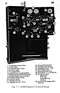
The EMD SD40 Control Stand
|
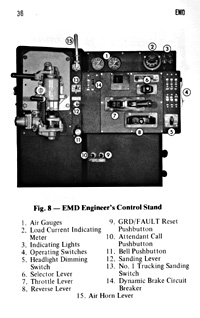
The AAR-EMD SD40-2 and SD50
Control Stand
|
The EMD Control Stand were equipped on NON
Dash-2 units such as the SD40s, GP35s and GP38s.
The Selector Lever has three
(3) positions which are # 1, OFF and B. The Selector Lever on the controlling
unit must be in the # 1 position for power, B position for dynamic braking
and OFF position when locomotive is parked. On trailing units, the lever
is always in the OFF position. This lever is spring loaded and returns
to center position after each movement. Its position is indicated by a
small illuminated window in the top left corner of the control stand.
A few units after June 1971 have three (3) position selector levers (PWR,
OFF, and B). The lever is placed in the PWR position for power, B for
dynamic braking, and OFF when locomotive is parked. On trailing units,
it is in the OFF position. The lever is NOT spring loaded and remains
in the position it was placed. Its position is indicated in an illuminated
window located directly above the selector lever.
The Reverse Lever has three
(3) positions which are Forward, Neutral and Reverse. The position of
the reverse lever on the controlling unit controls the direction of movement.
The reverse lever is removed from the control stand on trailing units
to lock the throttle and selector levers.
The Throttle Lever is used
for both power (when selector lever is in #1 position) and dynamic brake
(when selector lever is in B position). It has 10 positions: STOP, IDLE
and 1 thru 8.
The throttle is placed in the STOP position by pulling the throttle lever
outward (away from control stand) and moving it forward from IDLE to STOP.
This position shuts down all units in the consist except when isolation
switch of an individual unit is in START position.
The throttle placed in the IDLE position will be at idle engine speed
and power is not developed.
Positions 1 thru 8 power will increase the diesel engine speed and develop
a predetermined power output.
Using the dynamic braking is notchless on the throttle in runs 1 thru
8.
 |
 |
|
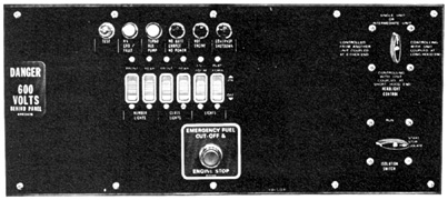
EMD NON Dash-2 Control Panel
|
EMD Dash-2 Control Panel
|
The AAR Standard Engineers Control Stand was used on ALL
of the EMD Dash-2 series locomotives, as well as on the GE Series-7 units.
This helped avoid confusion by having to learn several different types
of control stands for different models of locomotives. This control stand
was also installed on many of the older EMD units on major roads in the
late 1970s and early 1980s.
The Reverser Lever
has three positions: Forward, Neutral (center position) and reverse. The
position of the reverser lever on the controlling unit controls the direction
of movement (forward or reverse).
When the reverse lever is in neutral position, the throttle can be moved
into any position. The dynamic brake lever cannot be be moved from the
OFF position unless unless the reverse lever is in forward or reverse
position.
The reverser lever can be removed from the control stand when it is in
the neutral position. When removed, it locks both the throttle and dynamic
brake levers in idle and off positions. The reverser lever is to be removed
from the control stand on all trailing units in a locomotive consist.
The Throttle Lever has ten
positions: STOP, Idle, and Eight (8) power positions.
The throttle is placed in the STOP position by pulling the throttle lever
outward, away from the control stand, and moving it forward from idle
to stop. This position shuts down all units in the locomotive consist
except when the engine control switch is in START position.
The idle position allows the engine to run at idle speed, but no power
is developed.
Positions 1-8 will increase the engine speed. In each throttle position
a predetermined ampere output is developed.
The Dynamic Brake Lever has
three (3) positions: OFF, Set-up, and Braking Zone.
OFF is when the lever is placed in this position when dynamic brakes are
not being used.
Set-up establishes the dynamic braking circuits.
Braking Zone: This zone is numbered 1 to 8. The braking effort is increased
as the lever is advanced through the braking zone.
DYNAMIC BRAKES
Most of the Missouri Pacific locomotives did not have
dynamic brakes, however, there were some that did contain this feature
such as the SD40-2c (6000 Series Units) and some ex-Western Pacific units.
In addition, the Mo-Pac often used pool power from other roads, whose
power consisted of units with dynamic brakes. A brief explanation of the
varieties of dynamic brakes is listed here.
Standard Range Dynamic Brake
is the amount of retarding force developed as this brake increases with
the increase of the locomotive speed, reaching the maximum retarding force
at approximately 23 mph (with the 62:15 gear ratio). As speed increases
above 23 mph the retarding force will reduce gradually.
Extended Range Dynamic Brake provides maximum
retarding force in the entire speed range between 6 and 23 mph. This feature
works in conjunction with the Standard Range Dynamic Brake.
When an engineer changes operation from power to dynamic brake, he places
the throttle in the Idle position and must wait a minimum of 10 seconds
before applying the dynamic brake.
 |
|
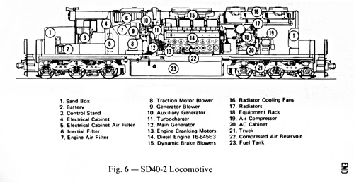
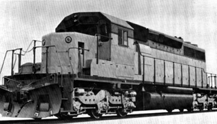
A Standard EMD SD40 Locomotive
|
|


