|
MISSOURI
PACIFIC GE UNITS
|

The
following is reproduced from actual operating manuals
|
GENERAL
INFORMATION
UNIVERSAL MODELS
All Universal
Models (U-Boats) were built with 16-cylinder turbocharged diesel engines,
with the exception of the U23 Model which was built with a 12-cylinder
turbocharged diesel engine.
U23B
Horsepower: 2,250 Weight:
265,500 lbs. Engine:
FDL-12 V-Type Fuel
Capacity: 3,250 gals.
Trucks: FB-2 (floating bolster)
Gear Ratio: 74:18
Minimum Continuous Speed: 11.5 mph
Cooling Water Capacity: 350 gals.
Tractive Effort: 57,2000
Sand Capacity: 60 cubic feet
Lube Oil Capacity: 300 gals.
Missouri Pacific's first group of 7 (seven) U23Bs delivered in 1973 came
with the AAR-B Trucks.
 |
|
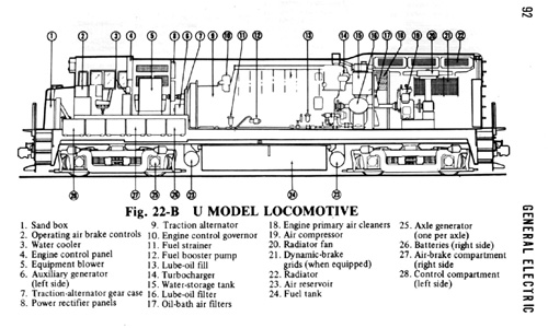
Standard
Configuration for the 4-axel Universal Locomotive Model
|
 |
|
Standard
Configuration for the 6-axel UniversalLocomotive Model
|
U30C
Horsepower: 3,000 Weight:
388,000 lbs. Engine:
FDL-16 V-Type Fuel
Capacity: 3,250 gals.
Wheels: 40 inches diameter
Gear Ratio: 74:18
Minimum Continuous Speed: 9.6 mph
Cooling Water Capacity: 385 gals.
Tractive Effort: 57,2000
Sand Capacity: 60 cubic feet
Lube Oil Capacity: 380 gals.
CONTROL STANDS
General Electrics Universal Models had three different designs
of control stands. The principal difference between the control stands
is found in the design of the controller. The controller is the portion
of the control stand which contains the reverser, throttle, and dynamic
brake or selector lever.
 |
 |
 |
|
Figure-1
|
Figure-2
|
Figure-3
|
(Fig.-1)
The Three-Lever Control Stand was included on all U25 and U28 models
as well as on U30 models built on or before the year 1968 also had this
design.
The Selector Lever has six
positions which are B, OFF, 1,2,3 and 4. If the above units were used
as lead unit, the lever must be placed in the 1 position, B for dynamic
braking or OFF when parked. Position 2-4 were used to control trailing
units equipped with manual transition.
The Reverse Lever has three
positions which are Forward, Nuetral, and Reverse. The position of the
reverse lever controls the direction of movement. The reverse lever must
be removed from the control stand of trailing units in order to lock the
throttle and selector levers.
The Throttle Lever has an idle
position, plus eight (8) major and eight (8) intermediate positions. The
major positions are makred by number, while the intermediate positions
are indicated with either a dot or 1/2 mark. Each numbered throttle position
changes the engine speed. The intermediate (one-half mark) position change
the amount of excitation.
The application of dynamic brakes is applied by placing the throttle lever
in idle position, the selector lever in B and then opening the throttle.
The dynamic brake is controlled by the numbered throttle positions.
(Fig.-2)
The Two-Lever Control Stand was included all U23 and U33 models, as well
as on several U30 models built after 1967.
The Selector Lever combines
the functions of the of the selector lever and the reverse lever. This
lever has five (5) positions which are used to select direction of movement
as well as the type of operation (motoring or dynamic braking). The mid-position
of the selector is OFF. The first position to either side of the OFF position
is for motoring. The second position to either side of the OFF position
is for dynamic braking.
The selector lever on the controling unit unit must be in the motoring
or dynaimc brake position in the direction of movement to develop power
or dynamic brake. It should be in the OFF position when the locomotive
is parked. On trailing units, this lever is to be removed from the control
stand.
The Throttle Lever has an idle
position and eight power positions.
The application of dynamic brakes is applied by placing the throttle lever
in idle position, moving the selector lever from the motoring position
to the dynamic brake position and opening the throttle.
(Fig.-3)
The AAR Standard Engineers Control Stand was used on ALL of the GE Dash-7
series locomotives, as well as on most EMD units. This helped avoid confusion
by having to learn several different types of control stands for different
models of locomotives. This control stand was also installed on many of
the Universal Models on major roads in the late 1970s and early 1980s.
Click Here For More Information on the Dash-7 Series Locomotives
The Reverser Lever
has three positions: Forward, Neutral (center position) and reverse. The
position of the reverser lever on the controlling unit controls the direction
of movement (forward or reverse).
When the reverse lever is in neutral position, the throttle can be moved
into any position. The dynamic brake lever cannot be be moved from the
OFF position unless unless the reverse lever is in forward or reverse
position.
The reverser lever can be removed from the control stand when it is in
the neutral position. When removed, it locks both the throttle and dynamic
brake levers in idle and off positions. The reverser lever is to be removed
from the control stand on all trailing units in a locomotive consist.
The Throttle Lever has ten
positions: STOP, Idle, and Eight (8) power positions.
The throttle is placed in the STOP position by pulling the throttle lever
outward, away from the control stand, and moving it forward from idle
to stop. This position shuts down all units in the locomotive consist
except when the engine control switch is in START position.
The idle position allows the engine to run at idle speed, but no power
is developed.
Positions 1-8 will increase the engine speed. In each throttle position
a predetermined ampere output is developed.
The Dynamic Brake Lever has
three (3) positions: OFF, Set-up, and Braking Zone.
OFF is when the lever is placed in this position when dynamic brakes are
not being used.
Set-up establishes the dynamic braking circuits.
Braking Zone: This zone is numbered 1 to 8. The braking effort is increased
as the lever is advanced through the braking zone.
|


