Train Management System (TMS) Central Railway
and Western Railway. WR TMS is up and running for few years now and this design
has been approved by RDSO.
CR has initiated process to install TMS to cover up major suburban traffic that will
cover up five segments, one major and 4 smaller ones.
Major section is CSTM - KYN.
Four minor segments are, Ambivli on Igatpuri side, Ambarnath on Pune side beyond Kalyan,
Bhiwandi Road on Vasai side beyond Dombivli and Dativli chord cabin beyond Diva on Panvel
side.
Most common misconception about TMS is, it a signal controlling system. That is not true.
It is indeed a TMS with multiple parameters, signals being just one of many.
The project is estimated to cost Rs. 37 crores or so and is expected to be ready by early
2008 or so.
Part 1 - TMS Requirements
Functional:
TMS is proposed to be provided in CSTM - KYN suburban section covering slow, fast, Mail /
Express corridors of Mumbai division.
In addition, it will also cover four minor segments are, Ambivli on Igatpuri side,
Ambarnath on Pune side beyond Kalyan, Bhiwandi Road on Vasai side beyond Dombivli and Dativli
chord cabin beyond Diva on Panvel side.
The response time between a changes of state at wayside station and its display at Central
control shall be less than two seconds.
General:
Train Describer / Management System (TDS) is broadly computer based information storage cum
retrieval system located in control office.
System collects signaling information such as signals, points, track circuits, route
setting, etc. from various station interlocking on Real Time basis.
It also collects train identification information from the train originating stations.
All this information is processed by the system and movement of trains at various
locations together with status of signals is displayed to authorities.
TMS is to provide effective method of regulating trains by monitoring their movement
and facilitates in taking timely decision for diversion of trains, induction and withdrawal
of rakes, planning reversal of rakes, etc.
It shall provide timely information to commuters through display boards and via announcements made on public address system
provided at all stations.
The system shall also generate punctuality reports, unusual reports, train graphs, rake
and crew links and other management reports.
The system shall provide data input to relay interlocking at few locations for remote
operation of points, etc. for control of train movements at these stations from Central
control office at CSTM.
The system shall have auto-route setting facility for tracks at CSTM station and yard.
Part 2 - Operation
Fiber Optic based communication is available at every station between CSTM and KYN.
Passenger Information System:
Microprocessor based train indicator boards are available at CSTM, PR, CLA and KYN.
EPROM based train indicator boards are available at MSD, SNRD, BY, CHG, CRD, DR,
MTN, SIN, VVH, GC, VK, KJRD, BND, MLND, TNA, KLV, DW, DI, THK.
Electronic Diode Matrix type train indicator boards are available at MBQ.
Train Operation:
1) At present, 110 EMU rakes are used for operation of suburban trains.
2) EMU car sheds are located at CLA, KLV and SNPD.
3) Electric loco sheds are located at CSTM and KYN.
4) Diesel loco sheds are located at CLA and KYN.
5) Crew booking and management is done at lobbies at CSTM, CLA, KPT, TNA and KYN.
6) Entry / Exit points for trains are:
a) MZN / BY yards for maintenance / holding of long distance trains.
b) Stabling sidings at CSTM, CLA, TNA and KYN. Additional sidings are planned at BY and
and THK.
c) At Diwa, trains from WR and KR enter the network.
d) Loco / EMU workshops at PR and MTN
e) Wadibunder, Sion, Trombay/Kurla, New Mulund for goods trains
Please refer to List of Stations & Station
codes.
Scope and future expansion:
1) It shall have provision for adding CSTM - PNVL harbor line
2) It shall have provision to add KYN - IGP and KYN - KJT
3) It should have capacity to handle following infrastructure.
a) 55 stations
b) 110 simultaneous trains
c) 40,000 indications
d) 8,000 remote commands pertaining to signal/point/route operation
e) 3,000 data inputs related individual train timetable
f) 40 modes on network in central control
Expandability:
1) Upto 80 stations
2) 150 simultaneous trains
3) 60,000 indications
4) 10,000 remote commands
5) 4,000 defined individual train timetables
6) Upto 50 modes on network in central control
Dynamic Performance:
The commissioned system shall have following dynamic performance parameters.
1) 150 simultaneous running trains
2) 50 route commands per minute
3) 200 other commands per minute
4) 1,000 indications per minute.
Please refer to Performance Requirements.
Part 3 -General Description and facilities at overview Mimic Indication panel
1) The overview mimic panel shall be vertical and placed in arc shape mode so that all parts
of the panel are visible with ease when seen from distance of 10 feet.
2) Station layouts can be arranged in two or more layers, top, bottom and middle.
3) The lowest row should not be less than 1.5 meters from ground to ensure proper viewing
angle.
4) Independent exclusive shunting lines need not be shown in the station layout. Where
shunt path leads to main line, path of shunt on main line only needs to be shown.
5) Station codes, signals, shunt/main track, train description shall be displayed. Field
objects should be as per geographical layout. For trains, only train #s shall be displayed.
6) The width, height of overview panel shall be so that it is able to accommodate 6 lines
from CSTM to SNRD, 4 main lines from SNRD - CLA, 6 lines from CLA - KYN.
7) Two harbor lines from CSTM - CLA, which are in planning stage, shall also be catered for.
At Diwa, where trains from WR and KR join CR system, adequate space should be provided for
indications to operator for all tracks & trains.
8) In addition, EMUs can join/leave CR system at CSTM, CLA, KLV and SNPD car sheds.
9) Sufficient space shall be made available between track indications for alphanumeric
display.
Specifications for DLP Display system:
1) Screen size: 67 - 70 inches diagonal
2) Imaging panel: DLP - Single chip DMD
3) Light Source: Dual lamp system - UHP, minimum power range 100 W with auto lamp
switchover, user replaceable lamp
4) Lamp use: Single to dual redundant operation. Hot standby lamp operation, i.e.
switching time in case of master lamp failure is virtually zero.
5) Resolution: SXGA Plus (1400 x 1050)
6) Power: AC 160v -240v 50 Hz
Please see Display
Locations at various points of CR network.
Part 4 - How WR TMS works
TMS at CR is still under development. However TMS at WR is operational for last few years
and this design is approved by RDSO. So I would use WR model for describing the working
of TMS.
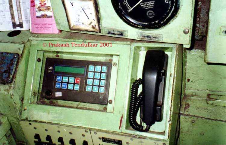
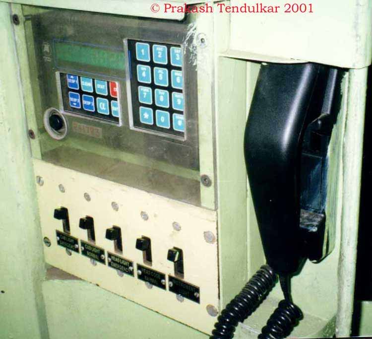
Every driving cab in WR has conical shaped antenna mounted on roof top. The TMS input
unit in cab transmits the driving cab # to central system. TMS1
and TMS2 .
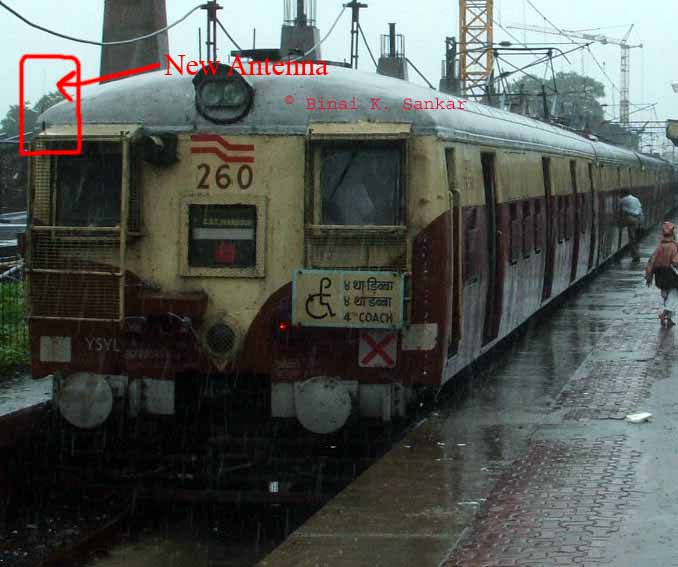
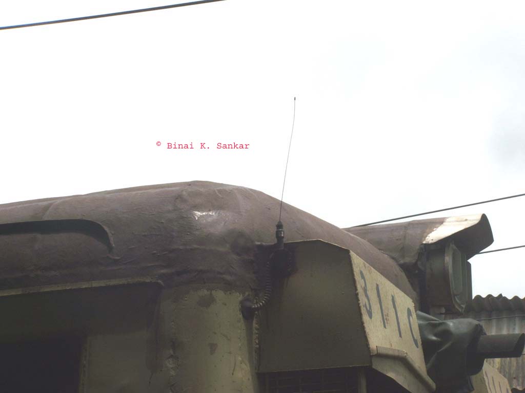
Antenna on CR EMU can be seen at CR Antenna1 and
CR Antenna2 .
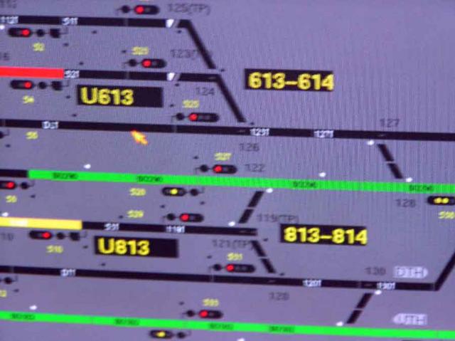
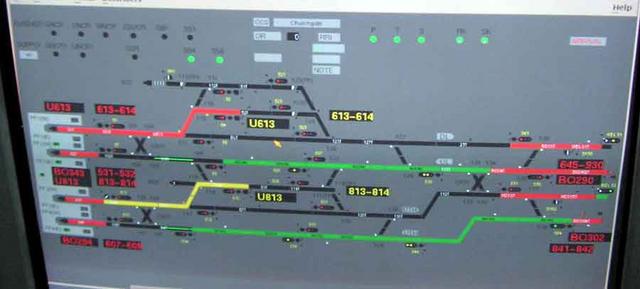
As a result, loco inspector at CCG or TNL at BCT can see details of rakes at CCG platform like:
Screen1 and Screen2.
So far we have accounted for unit # of rake.
Now the next question is, how to relate unit # with train #s and TT.
Every EMU bears a unique train # while plying on tracks. This # is one or two alphanumeric
characters long.
When EMU leaves car shed, it gets train # assigned and it is entered into TMS manually.
Similarly, a stabled rake arrives on platform at the beginning of day, ASM enters this
train # .
This accounts for six digit train
Identification in TMS as shown here
under item # 9.
In addition to train #, EMU also gets trip # consisting four numeric characters making it
easy to match with WTT.
Let's look at one EMU and her few trips during day. Details are from old WTT and
may have changed.
Train # AQ
Trip # 3 Dep BA 4:05 Arr BVI
4:40
Trip # 22 Dep BVI 4:46 Arr CCG 5:51
Trip # 51 Dep CCG 5:53 Arr BVI 6:58
Trip # 100 Dep BVI 7:05 Arr CCG 8:10
Trip # 155 Dep CCG 8:12 Arr BA 8:44 (Not on Sunday/Holidays. Else pick up Trip # 174)
On weekdays, her last trip would be:
Trip # 859 Dep CCG 22:39 Arr BVI 23:24 . She gets new Train # the next day and
ASM at BVI enters it into TMS.
Car shed may pick her up on Sundays/Holidays or leave her stabled at BA. Depending upon
action by car-shed, she may lose her train # or may keep it. On weekdays, she will continue
her trips for the rest of the day as Train # AQ.
Now with this manual input of train #, TMS knows about her trips, whether she has 9-coaches or 12-coaches.
Traction controllers (TNL) may change her route from Fast track to slow track and vice
versa but TMS knows the train # associated with unit so no input necessary. Only
when TNL assigns a working of another train to her, he keys in the changes into
TMS to reflect new trip # she will be working at.
Same scenario when Control Tower assigns
available platform for her which could be the same as expected or different from
what is expected normally, the display on platform and electronic announcements
will identify her correctly.
So TMS operator or ASM gets following screen. http://tinyurl.com/fo5pa He/She need not know
unit #, train # or anything like that.
TMS also gets input from signal circuits to know if that specific unit has passed signal
and her location.
TMS sends announcements to PA system at respective stations, sends input to display
showing ETA, sets indicators to reflect TT for the rake arriving on individual platform.
The whole system works without much interference under normal circumstances. However, things go wrong at times and lots of
manual input is required. That explains why every ASM, TNL and car-shed's SSE has TMS terminal handy.
More pictures of WR TMS can be seen at http://trainweb.org/railworld/TMS/
Back
to Railworld Index


