The PRR K-4s #1361
Steam Locomotive Restoration Project
Page 9
(This site is provided as a courtesy of the Altoona Railway Museum Club)
K4 Update: Spring 2002
The K4 Restoration Project has picked up a great deal of momentum since the beginning of the new year. The first quarter began with a meeting of the teams from the Museum and Steamtown. Congressman Don Sherwood from Scranton and Representative Rick Geist also attended the meeting. The group reorganized the operational structure and are expanding the team.
Four full-time men are currently working on the project. Bill Frederickson has been named on-site supervisor. Bill had been working on the neighboring Boston & Maine project at Steamtown until their funding ran low. According to Cummins McNitt, Frederickson is a welcome addition to the team. We are delighted to be able to pick up Bill during this transition period. He has 23 years of experience with the Blue Mountain and Reading; Wanamaker, Kempton & Southern; 1098 Rail Tours; and he worked on boilers in the Navy. He will be supervising Jeff Miller who has been on the project for several years now, as well as two new gentlemen from Central PA.
Art Leighty, a welder, and David Bechdel, a machinist, also have been added as full time employees on the project. Both men have been hired through the On the Job Training program offered through the state and the Southern Alleghenies Planning and Development Commission. Steamtown will be committing three full time employees to the project and will work through the end of September. It is hoped that an eighth employee will be hired before the end of March. With this new work force, it is anticipated that a great deal of work can be accomplished in a short time. Current plans call for the return of the K4 sometime in the final quarter of 2002.
Barry Claar, K4 Project Coordinator, recently provided an update on the work in Scranton for the Museum Board. He presented the following checklist of the work completed as of mid-February: The backhead has been formed and installed in place. Welding to the wrapper sheet is in process. Welding on the frame has almost been completed. 150 new stay bolt caps are currently being manufactured. Arch pipe holes have been bored into the door sheet, which is now ready for installation. Various brake parts have been welded for finished machining. The Tennessee Valley Railroad Museum is nearing completion of work on the wheels. The tender springs will be brought to Altoona soon for reconditioning & reinstallation. Keystone Restoration and Preservation is in the process of organizing a crew to begin work on the tender. Claar provided an optimistic summary for the Board. All in all, things are looking pretty good! (Spring issue of "The Standard", Altoona Railroaders Memorial Museum)
K4 Update: 03FEB02
On 3 Feb 2002, Tim Barney wrote:
"... Just got back from Scranton around 6:30 this evening. No pictures this trip, but will have some possibly next weekend if I can get there. Update for this weekend:
1. Volunteers were back from the Long Island group, set about building 4 heavy duty sawhorses to place parts upon to work on them. Also, 1/4" plate steel for ash hopper was cut out with a plasma cutter by a couple of those guys. (Sat)
2. New 30 ton remote crane (at Steamtown) is in and operational. We used it while bucking some of the stay bolts on the engineers side Saturday. (This means heavy stuff awaiting it's arrival can happen)
3. (Sat) Outer backhead sheet still temporarily in place for fitment/welding of patches between it and existing firebox sheeting. Jeff and I were attempting to seat some of the bolts for the stay rods that run laterally between the inner and outer crown sheets, but due to wear, some wouldn't fit, so Jeff started turning down the diameter of the shanks slightly (he and I were only two there Sunday, as Brian was off (due back tomorrow). Walter, myself and Chris Ahrens proceeded to press the bushings from the tender coupler and yoke Saturday. This has been completed after Walter machined a drift pin to match the inner and outer diameters of the bushings. Both parts to be cleaned up and checked for cracks. As for the coupler itself, Jeff is primarily concerned with the shank from about midpoint back to the pin.
4. I ground the edges of the 6 sheets that make up the ash hopper to clean up the cutting marks/remove slag. Several pieces need to be bent to conform to the original, and all holes need to be laid out and bored.
5. (Sun) I started doing crack assessment on the 8 tender truck spring hangers and 4 lead truck hangers. In a process similar to magnafluxing, a red oil-based die is sprayed on the parts, completely coating them. It is allowed to penetrate for about 10 minutes, then all excess is wiped off. A developer spray is then applied to the parts. This turns the surface of the part white, and anywhere a crack or void exists, the red die leeches out and marks the surface of the imperfection. (Editors note: You will notice white areas in several photos on prior pages. This is why they were white.) Several of the tender spring hangers had been previously repaired, and one had very poor quality welding done (marked by severe pitting of both the base metal and the welds themselves). Jeff plans to redo the welds eventually.
The steam dome appears to be fully riveted in place. Also, the air compressor is back from Backshop Enterprises and looking nice in red primer (sitting in the shipping crate). Chris Ahrens advised me that the cost of rebuilding the compressor was approx $24,000 because of how severely worn most of the internal components were.
Prior to this weekend
Front two main running board supports (both sides) have been installed after sandblasting and priming with aluminized paint. Most of the other studs are in place as well, with a few of the smaller ones (for piping brackets, etc) still needing replaced. The tender frame is sitting back on the trucks (albeit without springs) which have had the bearing surfaces against the bolster resurfaced."
K-4 Update: 18 Feb 2002
On 18FEB02, Cummins McNitt wrote: "... We are making a lot of changes at Steamtown these days. ... We have hired Bill Frederickson to work on the K4, full time. Bill is a superb mechanic who knows steam inside and out. He had been working on the neighboring Boston and Maine locomotive in the Steamtown shops, but their funding ran out. During this past week we hired an additional two men (David Bechdel and Arthur Leighty) through the Occupational Job Training program through the Southern Alleghenies Planning Commission. Both men are local displaced workers, one a welder the other a machinist. They are living in Scranton until the project's completion when they will return home to Altoona to continue their employment. We are also hoping to keep these two men on as full time employees of the Museum. We are currently in negotiations with Steamtown in hopes of acquiring several other employees to work on our locomotive, full time until the end of September. Jeff Miller continues his work on the K4. We have also instituted several internal operational changes. One of these is the appointment of one volunteer to serve as the lead volunteer in charge of volunteer management. We are also changing the working hours of the paid crew to run from Wednesday through Sunday, providing for maximum volunteer/paid staff coverage. We believe we will get a greater return for our investment in the long run with these changes. It is still our intention to bring the K4 home later this fall. Let me end by saying that bringing Barry Claar on board to supervise the restoration is the best thing the Museum ever did. He is extremely good at his work, supervising people and getting the research and information together to proceed."
K-4 Update: 24 Feb 2002
On Sunday, 24 Feb 2002, Tim Barney forwarded photos of the restoration which he took in August 2001.
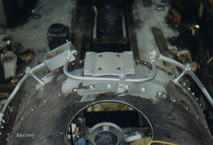
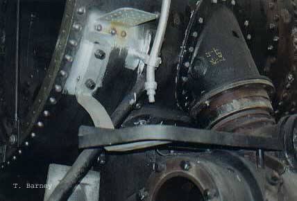
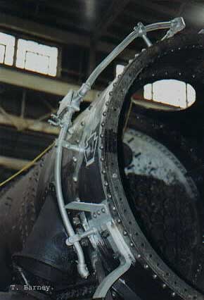
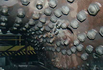
Steam Dome in place, prior to riveting. This actually shows the bolted-on steam dome, after the first 17 rivets have been installed (which took 4 of use 8 hours to do). Tim Barney Main running board brackets. This shows the underside of the main running board brackets sitting on a pallet awaiting sandblasting/priming. Tim Barney Headlight mount and conduit. This is a top-down look at the bracket that mounts the headlight assembly and the conduit that houses wiring for the headlight, front markers, and dynamo. Tim Barney Front running board and hangers. This shows the short running board sections that bolt on from the cylinders forward. Tim Barney Engineer's side conduit. This is a shot of the handrail/conduit from the engineers side of the smokebox. Tim Barney Cab support brackets. This is a shot of the main brackets that support the cab floor above the frame. Tim Barney Boiler throat flexible stay bolt detail. This is a close-up of the flexible stay bolts, many of which have been replaced. Tim Barney Boiler steps. This is a close-up of the 3 boiler barrel steps that allow access to the sand dome. Tim Barney Boiler steps and running board brackets. This is a photo of the brackets prior to being sandblasted and primed with aluminum-based paint. Tim Barney Air tank-running board supports. This is the combination running board and air tank support brackets. The thick one is the original, the thin one is plate steel that was made up for original restoration to replace a broken one, it will NOT be re-used (per Jeff). Tim Barney
K-4 Update: 09 March 2002
by Tim Barney
The ash pan parts photo shows the saw horses made by the Long Island restoration guys as previously mentioned.
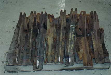
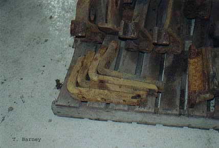
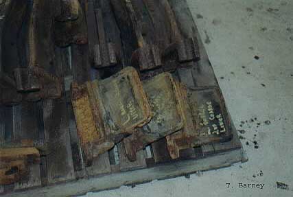
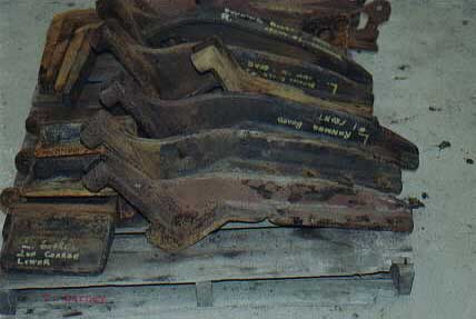
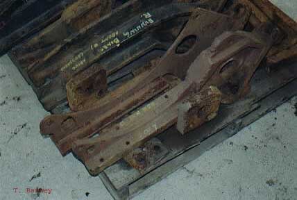
Layout of the holes as well as some bending on the sheets needs to be done before they can be assembled. The spring hangers photo shows some of the 8 tender truck spring hangers (the square pieces with the offset round boss in the foreground), the pony truck hangers (background on right), the coupler yoke (just left of middle of photo), and the coupler (far left). For scale and size, the coupler weighs about 500 pounds with a 6 inch square shank, the yoke is lighter (about 100 pounds or so) and the spring hangers probably run in the 25 pound range).
The photo of Jeff is him making sure the rough part will fit the gap between the firebox and backhead. We spent the last couple of hours on Saturday, and most of Sunday heating, bending, cooling, and grinding the part to fit with minimal gaps (which makes the welding easier). Most of Sunday, I spent on the top of the firebox hammering on a sacrificial piece butt welded to the end (topmost edge in photo). This was done so the plate itself wasn't struck with the hammer (causing potential flaws in the metal structure). Also, using a buck made from an old hammer head, we made some adjustments to the edge of the backhead to bring it in line with the side of the firebox (the area with the word back in soapstone) as the two pieces didn't meet perfectly at the time. Also, the sacrificial piece welded on the plate was my first attempt at arc welding (which garnered an "it looks fine" comment from Jeff - a real compliment to me, knowing Jeff's perfectionist view).
The frame repairs were done by Bill Frederickson (now project leader), who offered to let me try my hand at stick welding, but I didn't want to push my luck, as I'd rather screw up a piece of scrap instead of something critical.
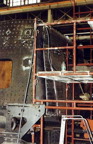
The fireman's vertical patch shows the radius patch (as I call it) at the end of Saturday, after a couple of heating/hammering sessions. The goal wasn't to bend it in one shot, but to gradually ease the radius in, tack welding as we went, to stabilize the part as it's bent. We did run into some minor trouble, as the sheet was slightly cocked foreward as we neared the end bending. Using the porta-power jack to attempt to stretch the metal slightly to allow for the mis-fit proved unsuccessful (even though we were only 1/8" inch out of alignment) so Jeff elected to using a cut-off wheel to finesse the edges into better alignment.
Walter was working on the stay bolts, machining round bar stock to the required size for the cross stay bolts at the top of the firebox that brace the top sheet just above the rivet strip. Due to lack of a steady-rest, Walter is forced to machine the length in 5 inch increments, with the tail of the stock passing through the lathe, and out the wall under the window behind him.
The triangular patches on the firebox have been finished welded to the firebox on the front, and have been bored for the stay bolts. Until the inner sheet work is completed, the backhead will not be permanently attached. As for the outer, as mentioned, there's one last patch piece to do (as of 2/16) and that is an approx. 8"x30" piece that will fill the gap between the two radius pieces across the top of the firebox. It's flat, so cutting and fitting will be greatly eased....... hope to get another update within the next couple of weeks. Tim
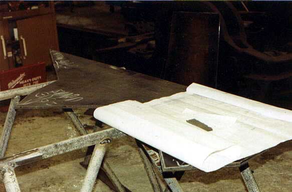 |
These are the parts cut by the Long Island restoration group for the new ashpan, along with a copy of the blueprints for the ashpan. Print specs state the ashpan is to be made of 1/4" tank plate steel. Tim Barney | 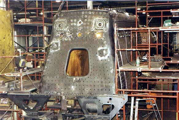 |
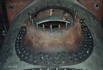
This is the backhead temporarily bolted in place for fitting of the patch panels that will join it to the rest of the firebox. Tim Barney |
 |
These are the two patch panels for the engineers side (total patch will be 5 pieces). The large triangular piece has been permanently welded to the firebox on the front edge, the radius piece for the upper edge of the firebox is tack welded for now. Tim Barney | 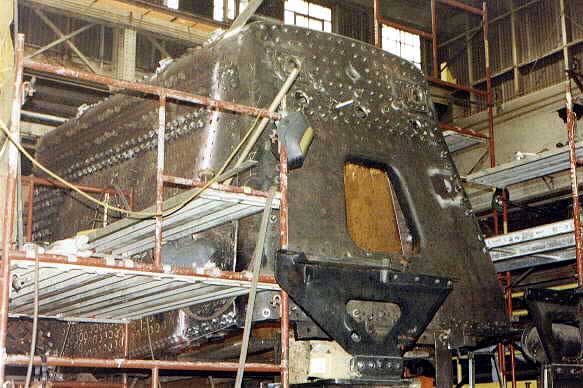 |
These are the two patch panels for the fireman's side, assembled in same manner as engineers side, the radius piece just recently having been fitted by Jeff and myself. Tim Barney |
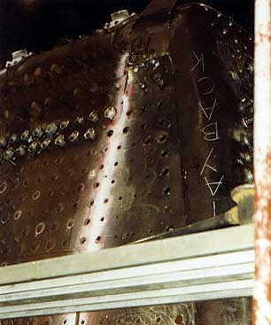 |
This is a closeup of the patch from the mudring vertically to the horizontal rivet strip. Just above, you see the radius piece bolted temporarily with the curve having been started. The sheet is bent by repeatedly heating the steel to incandescence (about 1600 deg F) and hammering with a 10 pound sledge hammer to bend the sheet. As it's bent, it's tack welded progressively further along to hold the shape. Tim Barney | 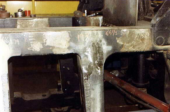 |
This shows some welding done on the fireman's side frame for the lead driver. Bob Frederickson performed the welding. The frame was cracked in this location, the crack having been ground out, and material replaced with welders rod (stick welding). Tim Barney |
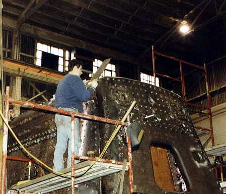 |
This shows Jeff fitting and marking the radius patch plate for the holes to temporarily bolt the plate into position for bending. After this piece is finished, a single flat plate will be cut to fit the final gap at the top (approximately 8"x30") Tim Barney | 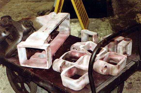 |
This shows the fault check applied to the tender truck and pony truck spring hangers, along with the coupler shank and yoke (the large rectangular piece) Tim Barney |
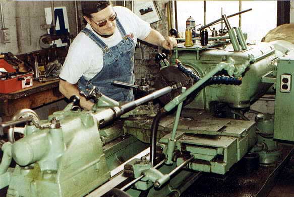 |
This is a shot of volunteer Walter Elvidge machining 72" long stay bolts for the cross bracing between the top and crown sheets at the top of the firebox. These will be threaded after machining. Tim Barney |
Stay tuned for additional photographs of the PRR K-4s #1361 Restoration!!