The PRR K-4s #1361
Steam Locomotive Restoration Project
Page 3
(This site is provided as a courtesy of the Altoona Railway Museum Club)
October 8 to 14, 2000
On Sunday, October 8, 2000, I made another trip to Steamtown. The following items were noted upon my arrival.
the right and left super-heater brackets (located inside the smokebox) had been riveted.
additional rivets which secure the smokebox had been installed
the old left front boiler "washout plug" had been cut out of the boiler and grinding had been taking place so that a new one could be installed. There are a total of 8 washout plugs located on the rear of the boiler. These allow the boiler to be flushed / cleaned.
the right front "T-iron" had been welded and test fit.
the left front "T-iron" had been installed.
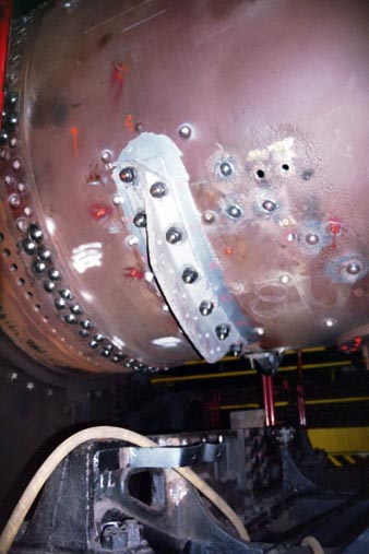
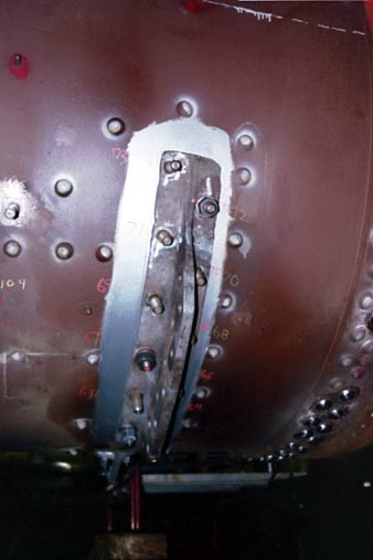
waist plates for the center two "T-irons" (which Brian and I had previously installed) were test fit.
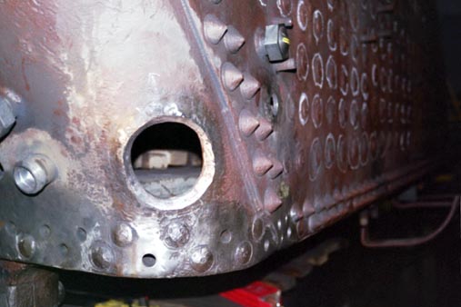
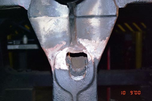
My task was to make the hole for the new left front (oval shaped, about 4"x5"x1") washout plug large enough for the new plug to fit. Note that volunteer Walter Elvidge had been working on this previously. The hole also needed to be large enough so that there was an additional 1/8" of space surrounding the new plug. The boiler in that area is about 1" thick and had to be ground down to about 1/2" for the welding process. The remaining 1/2" had to be tapered out at a 45 degree angle. Obviously we didn't want too much material to be ground off, so I would continuously check the fit of the new plug. Eventually, Jeff Miller made a template (which included the 1/8" ) which I could use. I did complete the grinding / preparation of this plug.
The (locomotive) left front washout plug hole, machined for installation of the new plug. Sunday, October 8, 2000
(Locomotive) Left front T-iron installed. Sunday, October 8, 2000
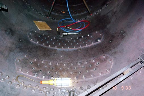
On Monday, 10/9/00, I spent most of my time inside the boiler. You will recall that Brian and I had spent alot of time on our last trip placing sealer on the center two "T-iron" studs and holes. Well, I took a portable heater (that looks like a hair drier) and heated up each one of the studs so that the sealer hardened. I did this for both the center "T-irons" as well as the left front one. After this was done, Jeff said I had to "caulk" each of the studs. This didn't mean getting out a tube of bathroom type caulk but the principle is basically the same. I had to take an air hammer with a "bit" that looked like a curved chisel or spoon. I then went to every one of the T-irons I mentioned and hammered around each stud until there were no seams where the stud protruded from the boiler.
|
|
The waist plates temporarily installed to the center two T-irons. Monday, October 9, 2000 |
|
(Locomotive) Right Front T-iron initially held into place. The studs still needed tightend and nuts installed. Monday, October 9, 2000 |
|
|
An interior view of the center two T-iron studs protruding into the boiler. Looking towards the rear of the locomotive. Monday, October 9, 2000 |
|
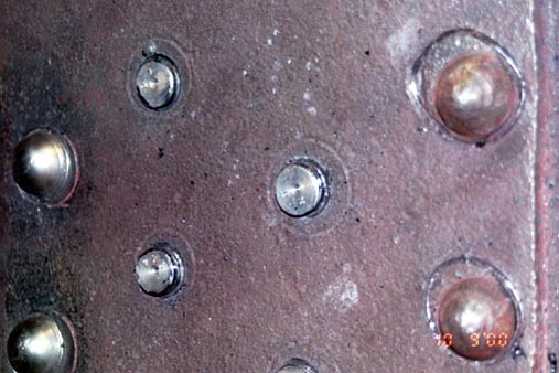
An interior view of the center rear T-iron studs protruding into the boiler. These have been caulked. Monday, October 9, 2000 |
|
|
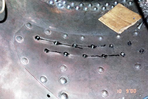
An interior view of the (locomotive) left front T-iron studs protruding into the boiler. Looking towards the front of the locomotive. Monday, October 9, 2000 |
|
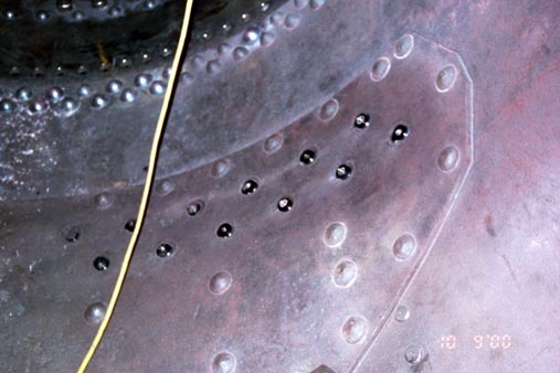
An interior view of the (locomotive) right front T-iron studs protruding into the boiler. Looking towards the front of the locomotive. Monday, October 9, 2000 |
Jeff had informed me that at some point during the last time he and other volunteers were riveting, the fire brick located on the door to the portable furnace had broken. Jeff located another brick and my last assignment for the day was to cut/file the brick to size, drill out the sight and bolt holes, install it, and then take "Quikcrete" to fill in any gaps or holes.
On Tuesday, 10/10/00, Jeff was trying to figure out how he was going to accomplish riveting the boiler in an area of the frame near the left side center. This area prevented the use of the standard air hammer and interfered with access by the operator. What Jeff had to do was find a special ("antique") air hammer in the shop, prepare it for use (as it had not been used or maintained in years), measure out the angles involved, and then "tack weld" a metal plate on to the frame of the locomotive. This metal plate would then act as a support/guide for the air hammer. I had to clean a couple parts for the "antique" air hammer which included taking fine grit sandpaper or files to polish the metal so that there were no burrs or rust.
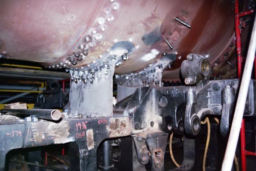
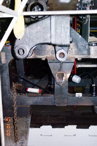
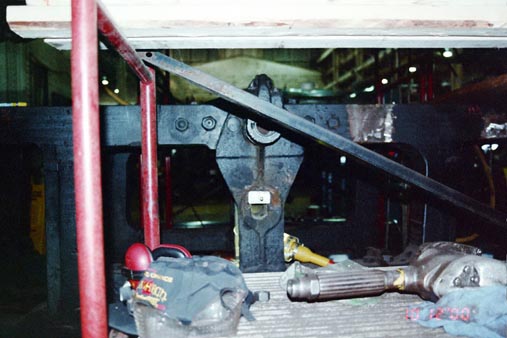
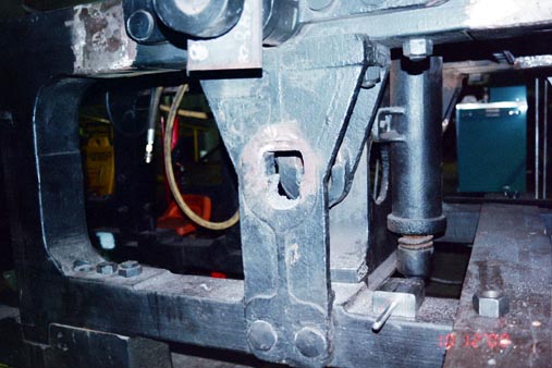
There are 4 areas on both the left and right side of the frame which hold bushings / pins which are part of the suspension for the K-4's drive axles. Specifically, they were the equalizer bar bushings and the equalizer bar balanced the load between the drive wheels. Two are located on the outside of the frame and two are located on the inside of the frame. The old bushings had previously been cut out and Volunteer Walter Elvidge had previously been working on preparing (sizing) the outer two left side holes for new bushings by using a grinder. Chris Ahrens had constructed a tapered template or gauge (about 1" x 3"x 4"; on a handle) which could be used to get the proper size. I completed preparing the left side outer bushing holes. I also assisted Jeff in installing / tightening the right front t-iron studs.
|
|
Locomotive Left Rear (exterior) equalizer bar bushing hole in the frame. Tuesday, October 10, 2000 |
|
Locomotive Left Front (exterior) equalizer bar bushing hole in the frame. Tuesday, October 10, 2000 |
|
|
Locomotive Left Front (exterior) equalizer bar bushing hole in the frame. A view of the frame. Tuesday, October 10, 2000 |
|
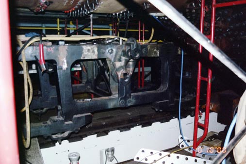
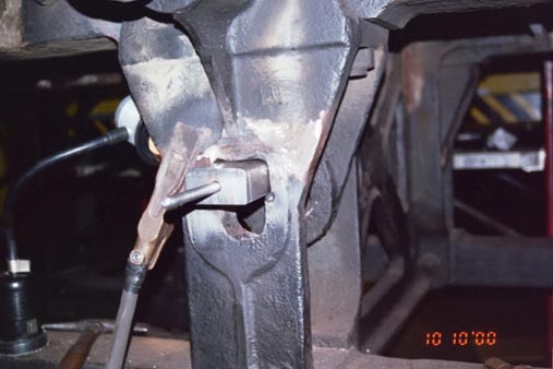
Jeff Miller heating the frame for the application of a bead of weld. The weld was required to build up the surface to ensure a proper fit of the bushing. Here he is at the (Locomotive) Left rear (exterior) equalizer bar bushing hole. Tuesday, October 10. 2000 |
|
|
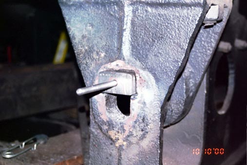
Locomotive Left rear (exterior) equalizer bar bushing hole in the frame. Here, the hole had been fitted to accommodate the bushing gauge. Tuesday, October 10, 2000 |
|
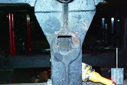
Locomotive Left Front (exterior) equalizer bar bushing hole in the frame. Here, the hole had been fitted to accommodate the bushing gauge. Tuesday, October 10, 2000 |
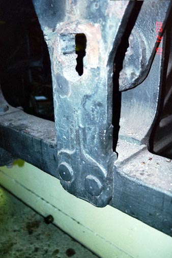
On Thursday, 10/12/00, I completed preparing the right side outer bushing holes. See Photos. I also heated the sealer on the right front "T-iron" studs and caulked them. Note that while we were looking at the frame of the locomotive, we found that several of the parts were stamped with the number "1361" however, it was obvious that several parts had been stamped with different numbers (which would indicate that the parts had been replaced at sometime during the locomotive's time in service. The number seen near the equalizers was "5371".
|
|
Locomotive right rear (exterior) equalizer bar bushing hole in the frame. This is prior to the hole being fitted to accommodate the bushing gauge. Thursday, October 12, 2000 |
|
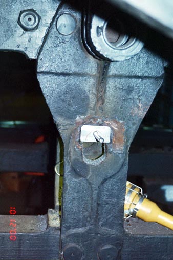
Locomotive right rear (exterior) equalizer bar bushing hole in the frame. Here, the hole had been fitted to accommodate the bushing gauge. Note the markings (dots punched into the metal...to the left of the light) which indicate that this part had been replaced at one time. The part came from locomotive #5371. Thursday, October 12, 2000 |
|
|
Another photo of the Locomotive right rear (exterior) equalizer bar bushing hole in the frame. Here, the hole had been fitted to accommodate the bushing gauge. Thursday, October 12, 2000 |
|
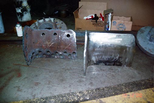
The section of metal laying on the left was the interior of the boiler/firebox in the left front corner. This metal had been removed so that the (locomotive) left front washout plug could be cut out / installed. Laying to the right is the new section of metal which will be installed. Thursday, October 12, 2000 |
|
|
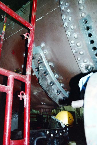
A photo of the locomotive right front T-iron installed. Thursday, October 12, 2000 |
|
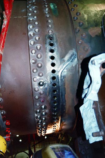
A photo of the rivet holes and prepared surface. This is where the rivets for the remaining portion of the front flue sheet will be installed. Thursday, October 12, 2000 |
|
|
Locomotive right front (exterior) equalizer bar bushing hole in the frame. Here, the hole had been fitted to accommodate the bushing gauge. Thursday, October 12, 2000 |
|
Locomotive right rear (exterior) equalizer bar bushing hole in the frame. Here, the hole had been fitted to accommodate the bushing gauge. This photo better shows the markings which indicate that this part had been replaced at one time. The part came from locomotive #5371. Thursday, October 12, 2000 |
On Friday, 10/13/00, I sandblasted various external smokebox conduits, handrails, fuse boxes, pins, and plates. I then assisted Jeff in polishing the holes in the boiler (and surrounding areas) for the installation/welding of the remaining portion of the front flue sheet. You will note in the photos that only half of the front flue sheet is installed. This is the original portion. The lower portion had to be cut out and remanufactured due to cracks and holes.
 |
Smokebox conduit / handrail / fuse box prior to sandblasting. Friday, October 13, 2000 | 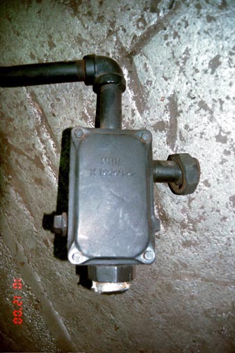 |
Closeup view of a section of smokebox conduit / handrail / fuse box prior to sandblasting. Note the PRR lettering. Friday, October 13, 2000 |
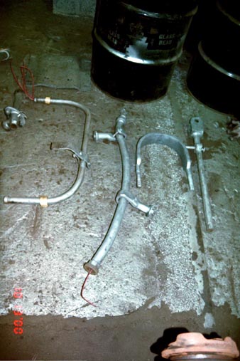 |
Smokebox conduit / handrail / fuse box & miscellaneous parts after sandblasting. Friday, October 13, 2000 | 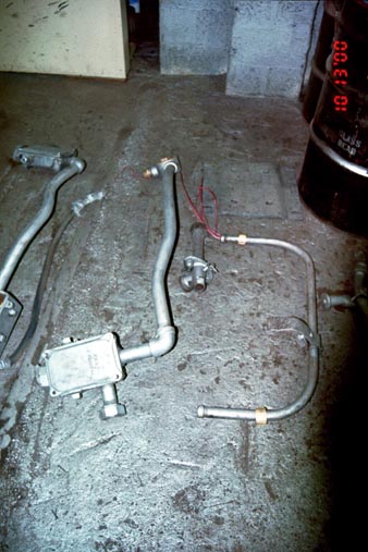 |
Smokebox conduit / handrail / fuse box & miscellaneous parts after sandblasting.Friday, October 13, 2000 |
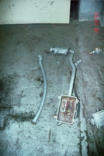 |
Smokebox conduit / handrail / fuse box & miscellaneous parts after sandblasting.Friday, October 13, 2000 | 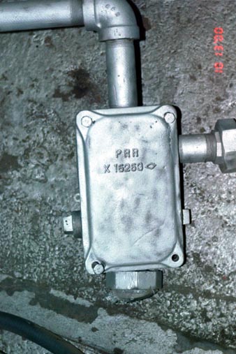 |
Closeup view of a section of smokebox conduit / handrail / fuse box after sandblasting. Note the PRR lettering. Friday, October 13, 2000 |
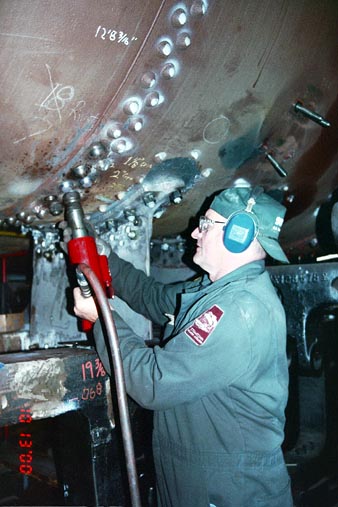
On Saturday, 10/14/00, volunteers Walter Elvidge and Wayne Laeppele (Wayne also worked on the original restoration in Altoona) assisted in riveting the boiler. Chris Ahrens had requested that several K-4 springs (located on palates buried as far back from access as possible) be moved out of parts storage in the roundhouse so that they could be sent out for refurbishing. Walter and Wayne then obtained a forklift and completed moving these parts. Meanwhile, Jeff and I completed preparing the smokebox and lower part of the front flue sheet for installation. This required mounting a "strongback" bar (steel) to the already installed front flue sheet. The purpose of this bar is to make the flue sheet as rigid and straight as possible for the mounting / welding of the new portion. Walter, Wayne, Jeff, and I then carried the new portion of the flue sheet inside the smokebox, and then aligned and bolted it to the smokebox. It will be welded then riveted in the next couple of weeks.
|
|
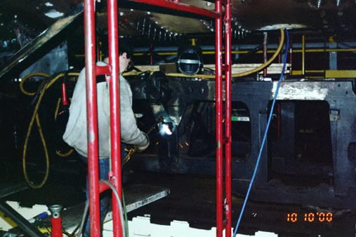
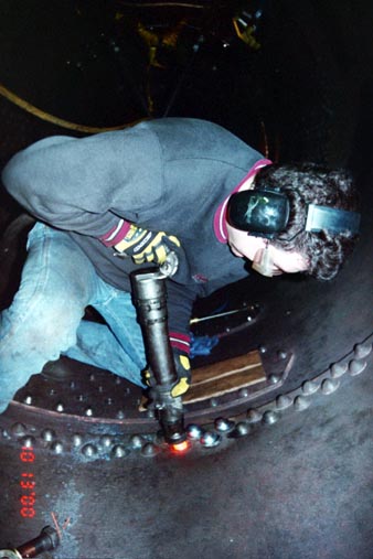
10/14/00, Volunteer Walter Elvidge preparing to rivet a boiler rivet (Locomotive Left front side) |
|
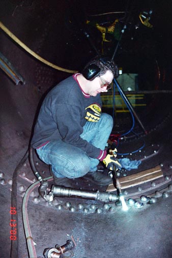
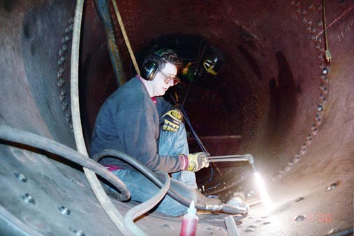
10/14/00, Jeff Miller (inside the boiler) heating the metal around a rivet hole prior to installation of a rivet. |
|
|
10/14/00, Jeff Miller (inside the boiler) using an air hammer to install a rivet. |
|
10/14/00, Jeff Miller (inside the boiler) shows us the installed rivet.. |
|
|
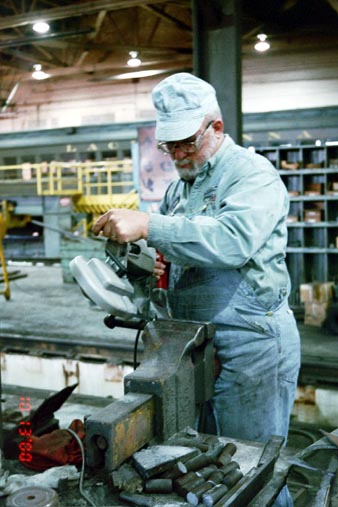
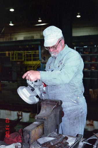
10/14/00, Volunteer Wayne Laeppele cutting a rivet to size. |
|
10/14/00, Volunteer Wayne Laeppele cutting a rivet to size. |
|
|
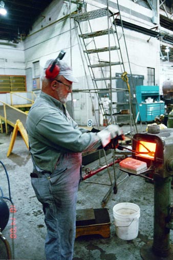
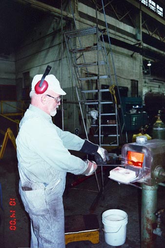
10/14/00, Volunteer Wayne Laeppele placing a rivet into the rivet oven. |
|
10/14/00, Volunteer Wayne Laeppele placing a rivet into the rivet oven. |
|
|
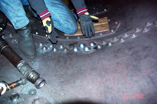
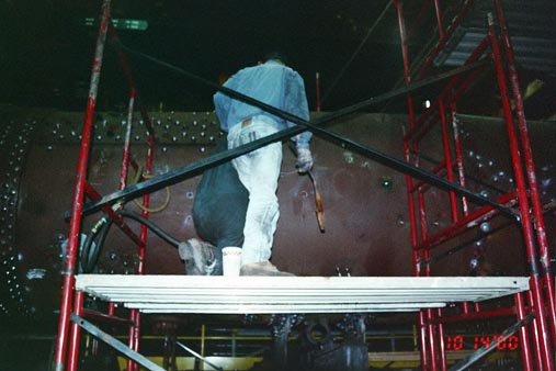
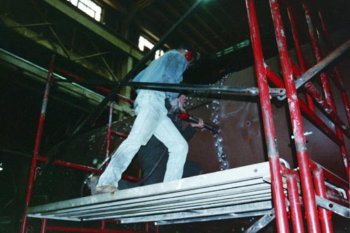
10/14/00, Volunteer Walter Elvidge (in green; in the foreground) riveting a boiler rivet (Locomotive Left front side) I stood behind him to brace him as we were on scaffolding. |
|
10/14/00, Volunteer Walter Elvidge (in green; in the foreground) riveting a boiler rivet (Locomotive Left front side) I stood behind him to brace him as we were on scaffolding. |
|
|
10/14/00, Jeff Miller (inside the boiler) heating the metal around a rivet hole prior to installation of a rivet. |
|
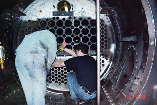
10/14/00, Volunteer Wayne Laeppele and Jeff Miller checking the alignment of the new portion of the flue sheet. It was just sitting in place at the time and was yet to be installed. |
(Railfest is a trademark of Railroaders Memorial Museum, Inc
. The logos for the Altoona Railroaders Memorial Museum is a trademark of the Railroaders Memorial Museum, Inc.
Photographs are by Chris Behe unless otherwise noted)