|
Web Update - January 2006 to July 2006 |
|
|
 Detailed view of
the new riveting inside the tender coal bunker. |
 View of the
riveting on the rear of the slope sheet including new ladder and
supports. |
 View of new ladder
added to the cistern area to aid in inspecting the inside of the tender
if needed. |
 Mounting the newly
fabricated backup light support bracket. |
 Another view of the
backup light support showing it’s location on the tender. |
 One of many pins
being fabricated to replace those that have worn out. |
 A new gib being
machined. Note the worn out gib in the foreground. It’s easy to see why
new ones were necessary. |
 A side view of the
gib machining process. |
 View showing the
pulling bar pin bearing housing on the front of the tender frame. Note
the damage due to rust and corrosion. |
 Another view of the
bearing housing from the top. |
 A pallet containing
the reworked spring hangers and crossheads. |
 The outer firebox
sheet is mounted for initial fitting. |
 View of the new
firebox side sheet and back-head. |
 View of the inside
of the firebox showing the back-head braces. |
 The side rods are
brought out of storage and about to undergo initial cleanup and
polishing. |
 The eccentric
cranks are set aside waiting cleanup and initial polishing. |
 Miscellaneous parts
are brought out of storage either for cleanup or repairs prior to
assembly. |
 The valve gear
links and link blocks are brought out of storage. It was necessary to
replace the link blocks with new ones due to wear. The new blocks were
fabricated in the machine shop. |
 Rivet work on the
tender truck bolsters. The rivets were replaced due to deterioration. |
 The new tender
springs arrive from the manufacturer. |
 The tender trucks
were turned upside down in order to replace defective rivets. |
 A view of the rivet
work. |
 Volunteer Charles
Cantrell polishing various valve gear components. |
 A view of the
completed valve gear components after polishing. |
 Initial reassembly
of the valve gear. This was performed to check for proper fit. |
 This view shows the
misalignment between the lift shaft arm and the radius rod hanger on the
fireman’s side of the locomotive. This is due to the correct realignment
of the reverse shaft and a twisted lift shaft arm. |
 A side view of the
reverse mechanism involved. Pictured are the lift shaft arm (top right),
radius rod hanger (middle), and radius rod (bottom). |
 Several flue tubes
are set in place to check for the proper distance between the front and
rear tube sheets. |
 This view shows the
misalignment between the lift shaft arm and the radius rod hanger on the
engineer’s side of the locomotive. Again, this is due to the correct
realignment of the reverse shaft and a twisted lift shaft arm. |
 Close up showing
the bend in the lift shaft arm. This will have to be corrected before
assemble can proceed. |
 An even closer
view. |
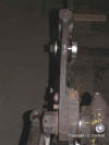 A view of the bent
fireman’s lift shaft arm. |

A view of the valve gear in general. |
 The rear tube sheet
has been tack welded into place at this point of the boiler assembly. |
 The compressor
hanger is brought out of storage. |
 The support gussets
for the spring saddles, on the tender trucks, had to be repaired prior
to installation of the saddles due to wear. Pictured here is the gusset
after needle scaling to remove rust and other buildup. It was necessary
to turn the truck upside down to do this repair. |
 Here you see the
trucks with the saddles and springs installed after repairs. |
 The tender frame
has a downward bow in the middle. A jack along with chains has been
installed to force the frame back in the proper direction. This will
take several weeks to accomplish if all goes well. |
 The tender tank and
several other assemblies and parts are place on a flat car for
relocation to the other side of the shop. |
 A close up view of
the frame, chains, and jack. |
 The frame, after
several weeks, is still trussed up in an effort to correct the bowed
condition. |
