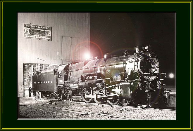
The PRR K-4s #1361
Steam Locomotive Restoration Project
Page 23
(This site is provided as a courtesy of the Altoona Railway Museum Club)
![]() January 2006 K4
Update (continued)
January 2006 K4
Update (continued)
These photographs were taken between July 2005 and January2006 by Charles Cantrell, 1361 Volunteer.
|
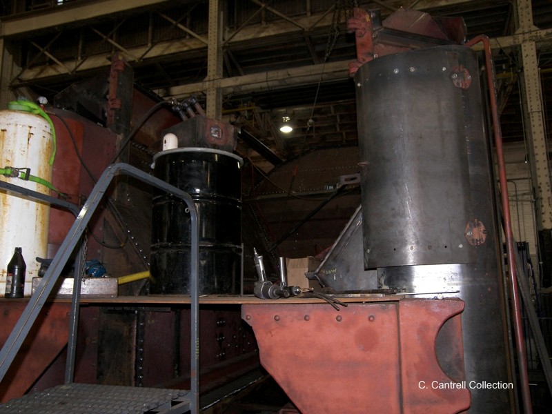
41. Another view. |
 |
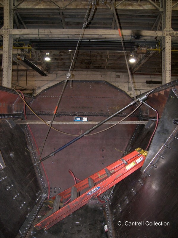
42. A view of the worn out rear tender sill section. In some places, the metal was non existent. |
 |
|
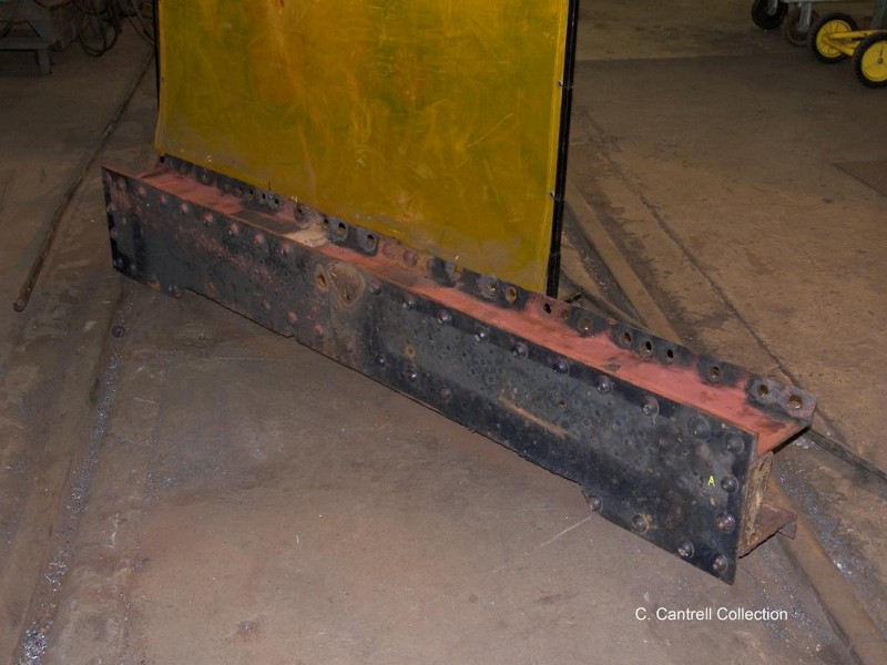
43. A view of the removed tender steps and section of air pipe. |
 |
44. Fabrication begins on replacement parts. Note the steel sheet clamped to the tender frame. |
 |
|
45. More rivet work. |
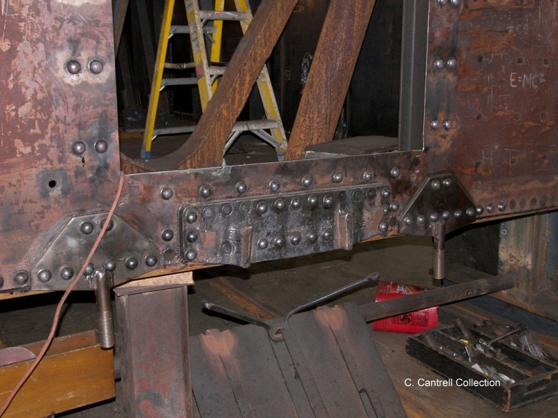 |
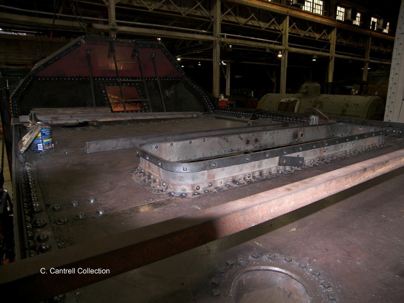
46. A view of the now riveted inside tender bracing and decking. |
 |
|
47. A section of the tender coal bunker rim had to be removed to facilitate riveting. It wil be welded and ground down to match the surrounding area. |
 |
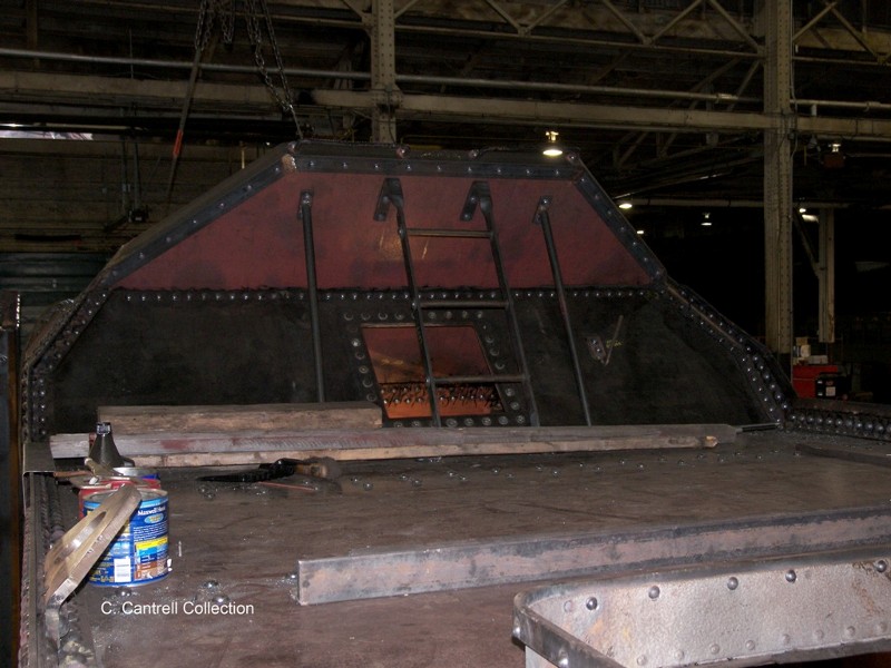
48. The tender slope sheet section is now reinstalled and the riveting begins on the tool boxes and surrounding areas. |
 |
|
49. A view of the coal bunker as riveting continues on the supporting rim rail. |
 |
50. Close up view of the riveting. |
 |
|
51. Fireman’s side toolbox is fitted into place. |
 |
52. A view of the rivet work on the tender deck and water hatch. |
 |
|
53. The slope sheet braces and ladder are riveted into place. |
 |
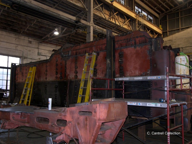
54. The worn out rear tender sill deck section. |
 |
|
55. The newly fabricated tender deck is installed for a trial fit. |
 |
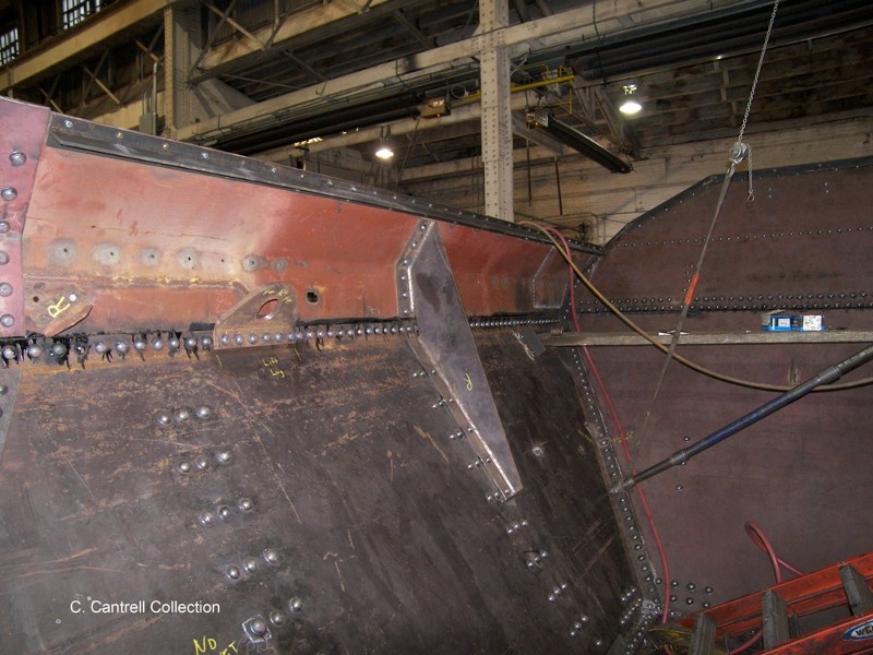
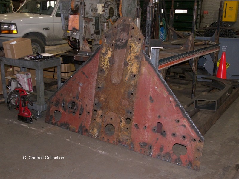
56. The newly fabricated rear tub sheet is being fitted into place prior to welding. Note the boiler firebox side sheet being held in place for mark up. |
 |
|
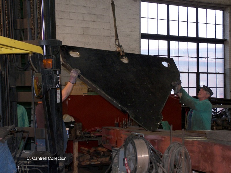
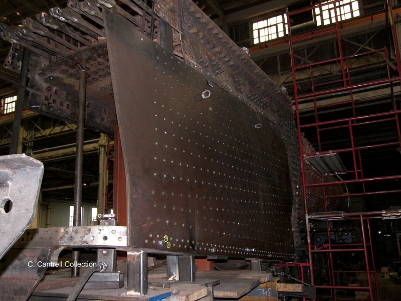
57. Another view of the outer firebox sheet during mark up. This sheet will undergo several installations/removals before it is ready for final install. |
 |
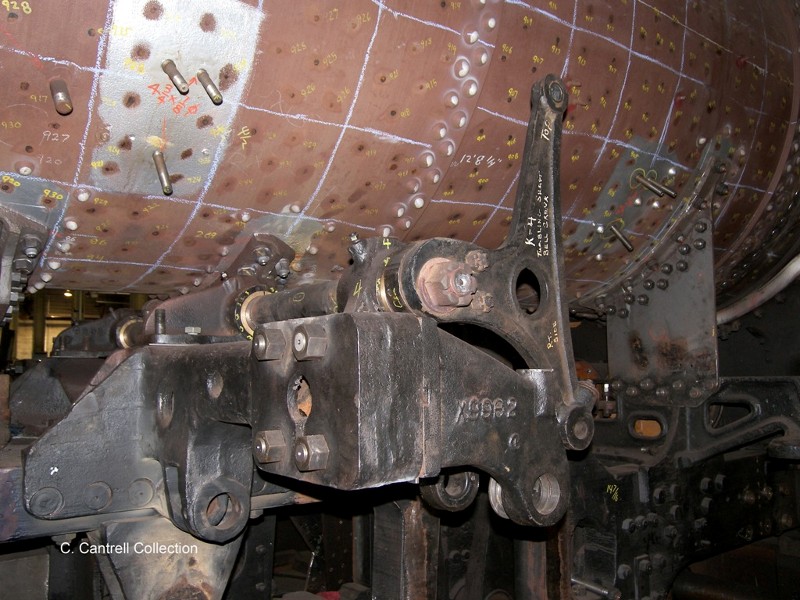
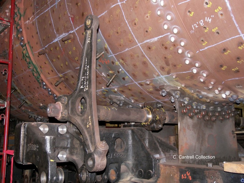
58. The fireman’s side reverse lever bell crank is fitted into place. |
 |
|
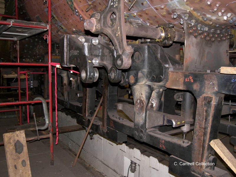
59. A view of the boiler showing a combination of new repairs including riveting, shafts, and bearing work. |
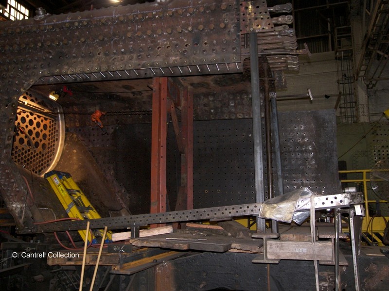
 |
60. View if the work on the break lever assembly. |
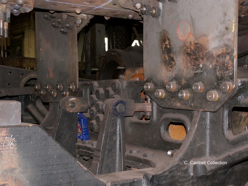 |
|
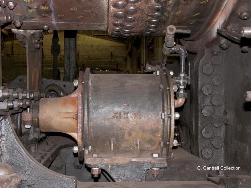
61. Close up of the rebuilt engineer side break cylinder. |
 |
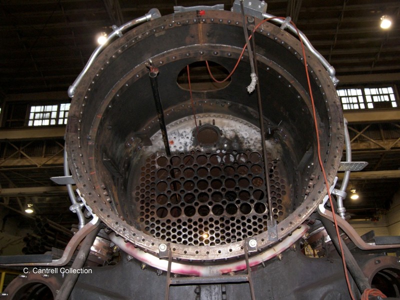
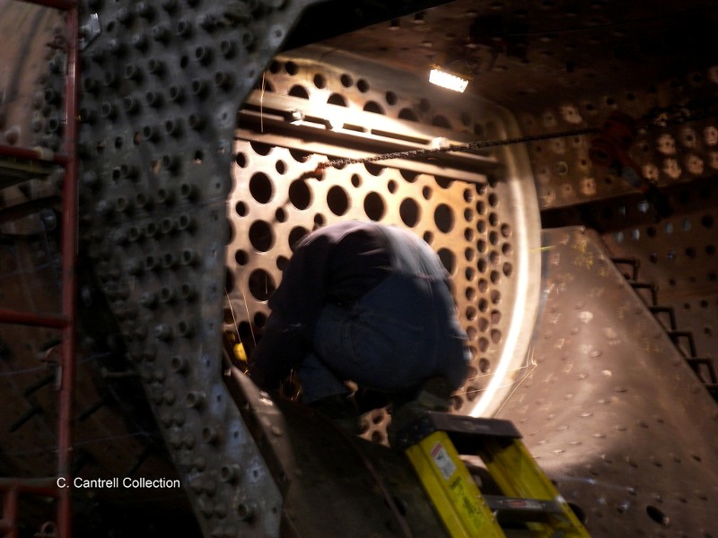
62. View of the smoke box interior showing the new rivet work. Note the installation of one of the boiler tubes for preliminary fitting of the rear tube sheet. |
 |
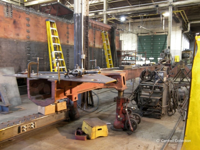
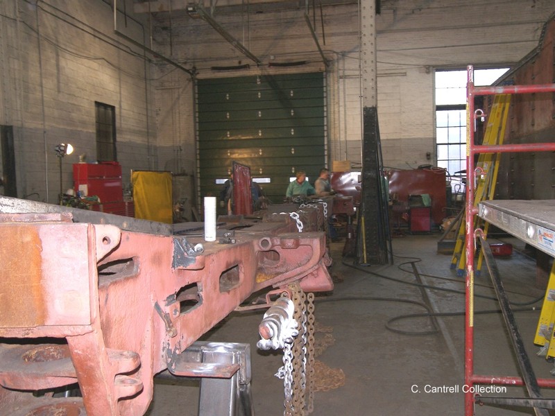
|
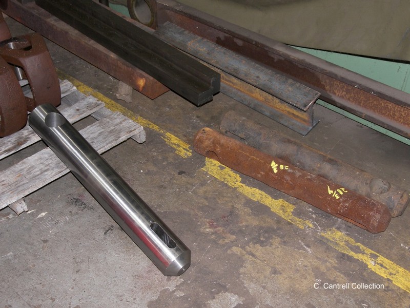
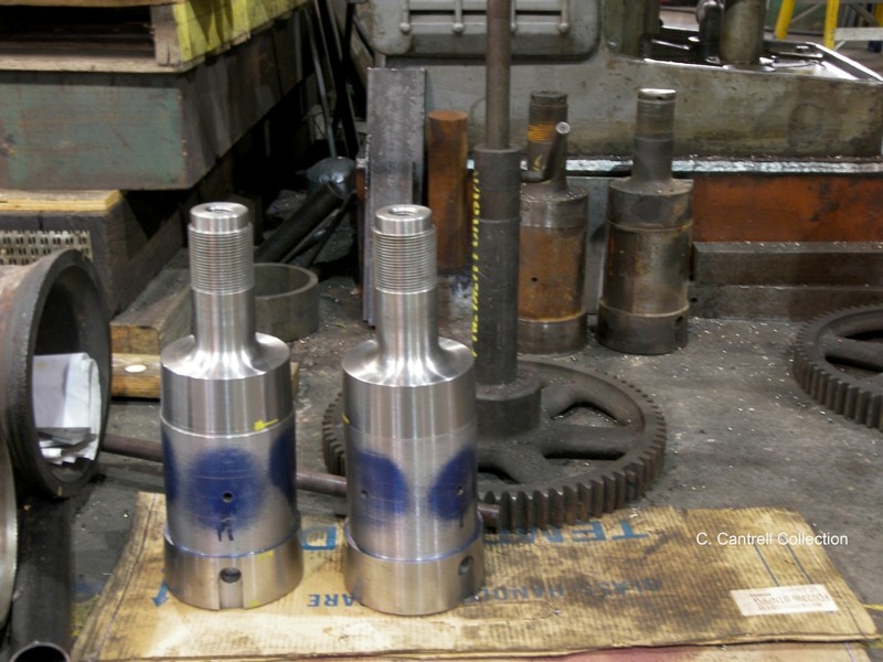
63. New bearings had to be machined to replace the worn out ones for both links. You can see one of the new bearings partially protruding from the link support. |
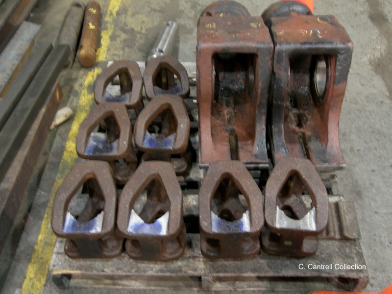
 |
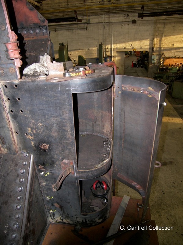
64. Close up of the tender frame. |
 |
|
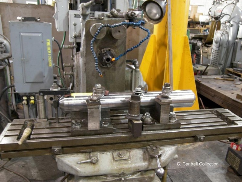
65. Close up of one of the newly fabricated pullin bar pins. The old pins can be see in the background. |
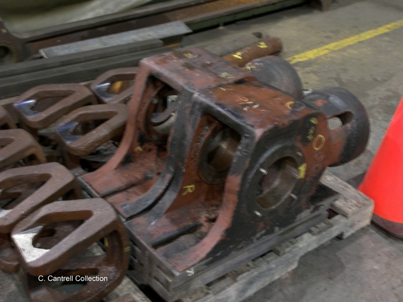
 |
66. Pallet containing newly machined spring hangers and the crosshead arms. |
 |
|
67. Close up of the crosshead arms. Like everything else, they required machining to bring them back to specs. |
 |
68. New crosshead wrist pins. The old worn out wrist pins can be seen in the background. New nuts will also have to be fabricated for both pins. |
 |
|
70. A close up showing the second Pullin bar pin being machined. |
 |
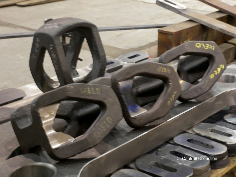
71. Close up if completed parts including spring hanger links, spring hangers, and the pullin bars. |
 |
|
72. View of the rivet work on the fireman’s side of the tender. The rivets still must undergo caulking. |
 |
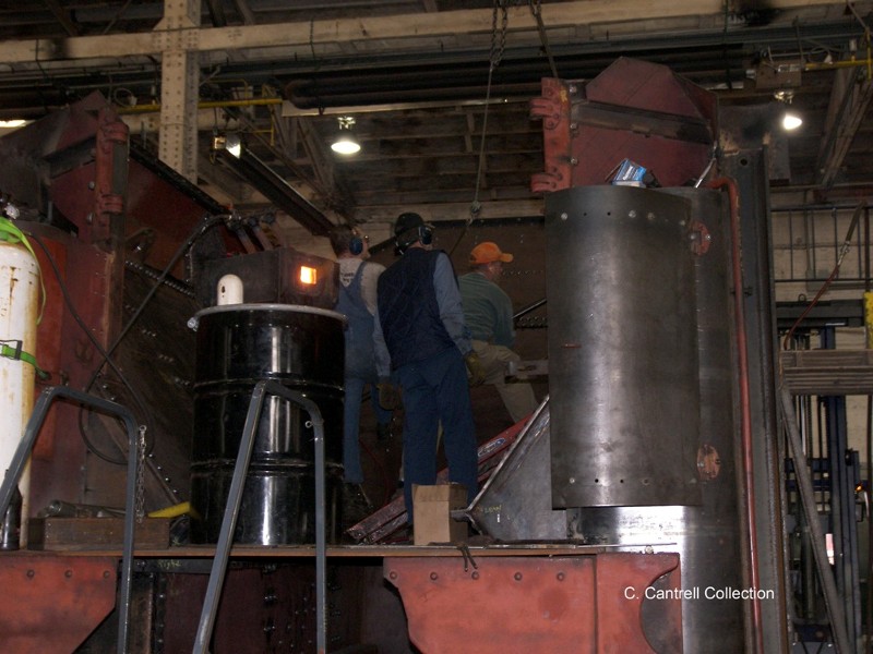
73. A volunteer from Altoona and myself fitting the rear tube sheet prior to welding into place. |
 |
|
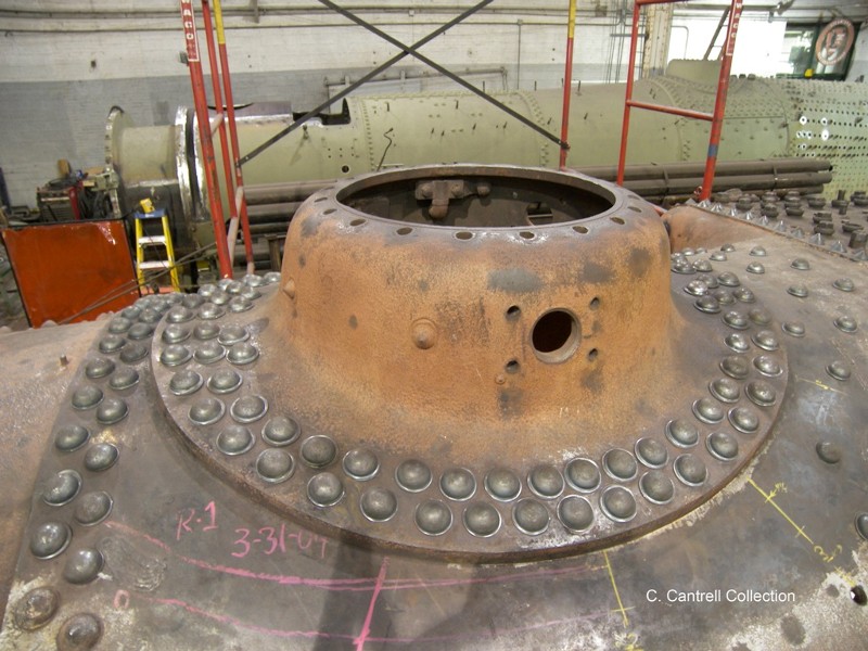
74. The steam dome is again riveted into place. |
 |
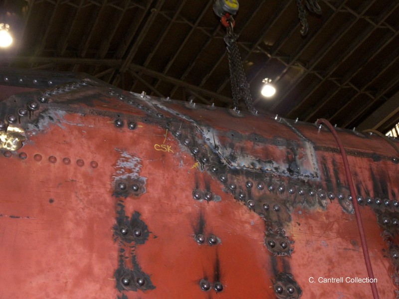
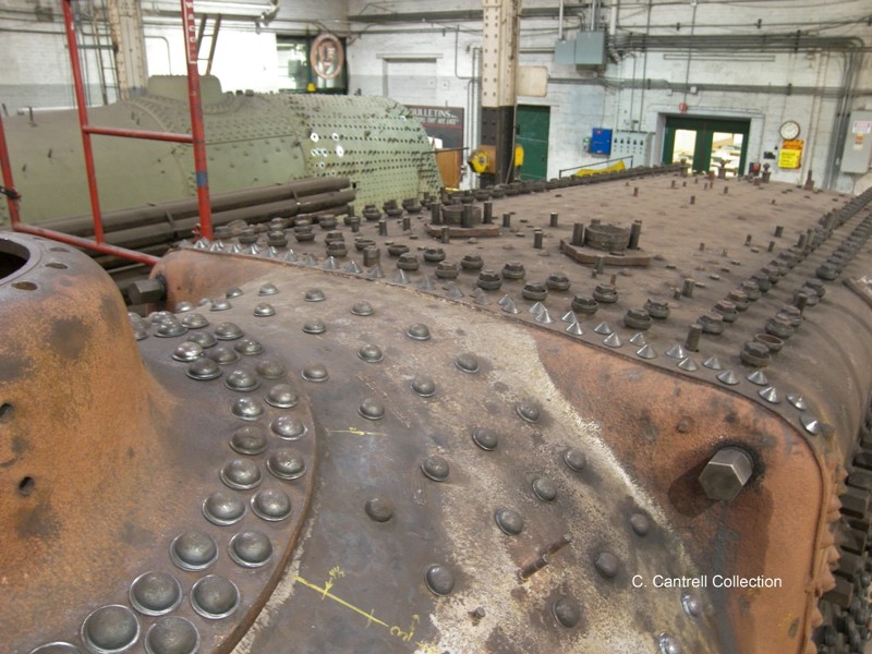
75. View of the rivet work completed on the top of the firebox and boiler. |
 |
|
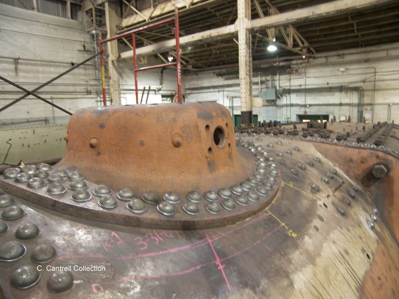
76. Another view of the work. |
 |
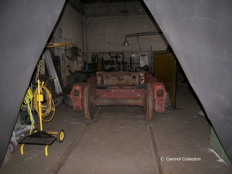
77. The tender trucks inside the weld shop for repairs. |
 |
|
78. Walter Elvidge leads two volunteers from Altoona during rivet installation on the inside of the tender. |
 |
|
All, Thanks for enduring the delay on website updates. Future updates will be posted intermittently. Regards. The Webmaster.
Stay tuned for additional photographs of the PRR K-4s #1361 Restoration!!