TrainWeb.org Facebook Page
Rules for Operating with Digital Command Control on NTRAK Layouts

This page has moved permanently. If you are not redirected automatically, follow the link to https://nrmrc.org/dcc/app-notes/rules-dcc-design-and-operation-ntrak-layouts

Track Spacer

NRMRC Logo

Digital Command Control

DCC Logo

Rules for DCC Design and Operation of NTRAK Layouts

by
John M. Wallis
Digital Master
North Raleigh Model Railroad Club


Track Spacer
Introduction

Digital Command Control (DCC) is widely used on NTRAK layouts. Its use can present a challenge to those who design, setup and operate NTRAK layouts. Based on experience from many NTRAK layouts at train shows, a set of rules for DCC operations on NTRAK layouts evolved, tried in other shows, modified and modified again as necessary. Special information and rules are included throughout this document for large NTRAK layouts in excess of 100 modules; these are clearly marked.

This page provides details of these rules and how to apply them to NTRAK layouts. You can scroll through the entire document or go quickly to individual rules by clicking on the desired rule below. A PDF version of this document formatted for printing is available at http://trainweb.org/nrmrc/dcc/DCCNTRAKDesignRules.pdf. Adobe Acrobat Reader is required to read the document. To download the document to your computer, right click the link then select "Save As" from the dialog box.


Rule 1

Appoint a Digital Master

Rule 2

Plan the Digital Layout Design as Carefully as the Layout

Rule 3

Standardize Booster-to-Track Wiring and Phase the Boosters

Rule 4

Reversing Loops and Wyes Have Special Requirements

Rule 5

Review Electrical Characteristics of All Modules in the Layout

Rule 6

Like Oil and Water, Don't Mix DCC and DC (Analog)

Rule 7

Use Power Supplies Matched to the Power Boosters

Rule 8

Only One Command Station Can Command

Rule 9

Radio Throttles are Better than IR Throttles

Rule 10

Be a Good Neighbor to Other DCC Layouts at a Train Show

Rule 11

To Analog or Not to Analog, That is the Question

Rule 12

Power Each UR91 Radio/IR and UR90 IR Receiver Individually

Rule 13

Power Each UP3 when UT1 and/or UT2 Throttles are Used

Rule 14

Old Batteries Never Die, They Just Lose Their Charge

Rule 15

Clean the Track and Clean the Wheels

Rule 16

Test the Layout Following Setup: Coin Test

Rule 17

Test the Layout Following Setup: Stress Test

Rule 18

Provide a Means of Programming Decoders

Rule 19

Identify Ownership of All Digital Equipment


The North Raleigh Model Railroad Club (NRMRC) and many other NTRAK clubs have adopted the Digitrax Digital Command Control System. Much of the information contained in these rules reflects the use of Digitrax equipment. The general concepts of these rules apply to DCC systems from all manufacturers and to layouts in all scales.

Your comments, corrections and suggestions are solicited. Send Email to John.

Top of Page

DCC Operations Page

DCC Home Page

NRMRC Home Page


Track Spacer

Rule 1   Appoint a Digital "Master"

This person is fully responsible for and is the final authority for all aspects of the digital design for the layout, and for setup and for digital operations of the layout during the Show. No changes should be made to either the digital design of the layout or the operating procedures without the agreement and approval of the Master. The club member most knowledgeable in DCC and the system being used should be the Master; a guest Master may be appointed if considered appropriate by the host club. The Master "reports" to the overall Show Superintendent for the Club.

The Digital Master selects the DCC system to be used for the layout, which is normally the system used by the host club. The Master should be sure that the owners of all visiting modules are aware of the system chosen. As well, the host club normally provides the Command Stations and Power Boosters, although for very large layouts other clubs may be requested to bring equipment. Visiting module owners can contribute to the setup by bringing compatible equipment (cables, boosters, wireless throttles, etc.).

Larger Layouts
For larger layouts consider appointing one or more Assistant Digital Masters (ADM). The ADM will help spread the effort during setup and test, and ensure a correctly operating system. The ADM can substitute for the Digital Master when and as needed.

Digital Master Train Show Summary Sheet
With three different types of Digitrax throttles, two types of Command Stations and the PM4 Power Manager, the Digital Master and ADM need a summary of relevant information in a concise, clear format for quick access without the need for product manuals. The Digital Master Train Show Summary Sheet is available as a PDF document (Adobe Acrobat Reader required) at http://trainweb.org/nrmrc/dcc/tsss.pdf. Left click on the link to open the Summary Sheet or right click then select "Save As" to download the document.


Top of Page

DCC Operations Page

DCC Home Page

NRMRC Home Page


Rule 2   Plan the Digital Layout Design as Carefully as the Layout

Determine the number of Boosters, Radio/IR Receivers, Throttles, Universal Panels and amount of LocoNet cable necessary to handle the configuration of the layout and the operations planned for the Show. Know who is supplying what equipment (if not Club-owned) and when it will be available during setup of the layout. Be sure to have a spare Command Station and Radio/IR Receiver.

Keep the following items in mind when determining how many Boosters you will need:

  • If you run lighted cars (e.g. Kato passenger cars) be sure to include their current draw in any Booster current calculations. Each car with the Kato standard lighting unit consumes 60mA.

  • Since NTRAK requirements for feeder cables are 20ga minimum or 18ga zip cord (per the Electrical Standard in the NTRAK manual) vs. the 12ga desired, 14ga minimum recommended for DCC, we must base our Power Booster spacing on 20ga feeders and assume a corresponding voltage drop. This means we should keep our Booster districts small and use additional Boosters as necessary to ensure full power is available anywhere on the layout.

    It is not simply a case of replacing 18/20 gauge wiring with 12/14 gauge as the largest wire that will easily fit in the holes in the terminals on the Cinch-Jones connectors used on NTRAK modules is 16 gauge, but this does help.

    A set of Recommended Practices for Module Wiring have been developed and are published at http://trainweb.org/nrmrc/dcc/ntrakdccstd.html. The use of these Recommended Practices for new module wiring and retrofit to existing modules is strongly recommended.

  • Boosters should be located at the geographical center of their district rather than at one end in order to minimize any voltage drop.

There are two general methods of powering an NTRAK layout — centralized and distributed.

  • With Centralized powering all the DCC control equipment (Command Station, Boosters, UR-91, etc.) are located in a single control case generally located in the center of the layout, with long tentacles of 12 gauge or larger wire connected to the modules every 15 to 20 feet around the layout to minimize voltage drop. There is usually one Booster per track.

    Centralized powering works well for a fixed size layout such as, for example, 30' x 50'. It can easily be used for a smaller layout, but is difficult to extend for a larger layout. The control case can be very heavy, as can the connecting cables. The only LocoNet outside of the control case is for throttles.

  • With Distributed powering the layout is divided into the needed number of electrical districts and the Boosters are physically located under the modules at the geographical center of their district. They are connected together and to the Command Station via LocoNet cables. Distributed powering is much more flexible, especially as the size of the layout increases.

For NTRAK layouts with Distributed powering it is more cost effective to power each power district using a DB200 8A Booster with a PM42 Power Management System to distribute power to all NTRAK tracks (red, yellow, blue, green) than to use a single 5A Booster such as the DB100 or DB150 per track. Each track is powered from one section of the PM42. The length of the power district depends on the acceptable voltage drop at the far ends of the district based on 20 gauge wiring. Each PM4 section is configured as a circuit breaker.

Each section of the PM42 could be set as low as 1.5A, but if lighted passenger cars are used the setting should be at least 3A. The lower the current setting the less the voltage drop at the end of the power district. With a PM42 setting of 1.5 or 3 Amps the electrical district could be about 60 feet long.

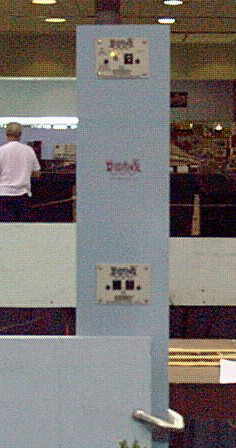
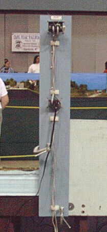
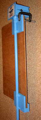
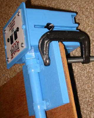
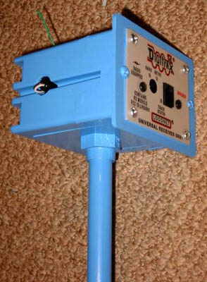
There must be at least one UR91 radio receiver for the layout, but two or more may be necessary depending on the size and shape of the layout and the electrical characteristics of the building, in order to minimize any dead spots. In many DCC layouts the UR91s were mounted beneath the layout. The North Raleigh Model Railroad Club has constructed a "radio tower" to ensure the main UR91 is about 3 ft above the surface of the layout. (Other receivers, when used, are mounted wherever convenient.)

Note:

A single UR91 can support at least 10 DTxxxR throttles and a single UR90 can support at least 10 DTxxxIR throttles.

If IR throttles are used, several UR90 and/or UR91 receivers will be necessary around the layout to ensure full coverage. Remember that IR is line-of-sight only. IR receivers must be mounted on a tower-type structure, like the radio tower.

The radio tower, shown in the photographs, is a 36" x 5-3/8" x 3/8" piece of wood, painted to match the module skyboard, with the UR91 mounted in a cutout at the top and an optional UP3 mounted about 18" up from the bottom. The tower is simply clamped to the back of a module located centrally on the layout. This tower effectively eliminates almost all electrical dead spots.

Radio Tower Photo Front

Radio Tower Phot Rear

Front view of Radio Tower showing UR91 receiver at top and UP3 just above the skyboard. Design allows for different height skyboards on modules.

Rear view of Radio Tower. UR91 is at top and UP3 in the middle. Tower is clamped to module and skyboard. Cables run to Command Station and wall-wart.


Radio Tower Box 1

Radio Box 2

Radio Box 3

Here is anopther type of radio tower using a plastic conduit boxe for the UR91 and conduit as the pole, developed by Bob Pawlek.

Until it becomes standard practice to mount a LocoNet jack in every NTRAK module, UP3/UP5 Universal Panels or equivalent must be mounted at convenient intervals around the layout. These are required for plugging in wireless throttles to select locomotives or to regain control as necessary. The NRMRC uses a spacing of roughly 20 feet. This was chosen because Radio Shack sells 6-conductor cable with RJ12 plugs in 25' lengths (Catalog No. 279-422).

The Universal Panels are simply screwed to the front of several modules using a couple of small wood screws. As well as the Digitrax UP3/UP5, the PH-UP Throttle Panel kit made by Loy's Toys (no longer available) and the UTP/TTX from Tony's Train Exchange can be used.

For flexibility in connecting LocoNet cables around the layout, you should have a supply of Loy's Toys PH-LL LocoNet Link which has 4 RJ-12 jacks (6-wire) that can be used to handle multiple LocoNet branches, as well as some 6-conductor in-line couplers (Radio Shack Cat. No. 279-420).

LocoNet cable should not be allowed to sit on the floor underneath the modules as the connectors can be easily damaged or pulled off should someone step on a cable or put a heavy box on it underneath a connecting point. Hang it up. Use twist ties, cable ties, Velcro straps or plastic twist-lock ties (Radio Shack Catalog No. 278-1664).


Top of Page

DCC Operations Page

DCC Home Page

NRMRC Home Page


Rule 3   Standardize Booster-to-Track Wiring and Phase the Boosters

The DCC signal applied to the track appears to be an AC signal, but it is not. It is a bipolar DC signal, thus track polarity remains an important issue, just as it is with DC. NTRAK has established a wiring standard for NTRAK modules — the wide pin of the standard NTRAK Cinch-Jones connector is connected to the rail closest to the front of the module. Let's modify this standard for NTRAK layouts controlled by DCC:

The wide pin of the standard NTRAK Cinch-Jones connector is connected to the rail closest to the front of the module, and to the Rail A terminal on the Boosters.


Building a Power Connector Cable

  • Use 16ga lamp cord. 16ga is about the largest gauge wire that can easily be soldered to the Cinch-Jones connector pin solder lugs. The insulation on the lamp cord is smooth for one wire and ribbed for the other. Create a "Y" at one end, and solder the Cinch-Jones connectors (one male and one female) to the ends of the "Y". For consistency, connect the ribbed wire to the wide pin in the Cinch-Jones connector.

  • Cut the lamp cord to the desired length, but keep it as short as possible. A length up to about 3 feet will have negligible effect on voltage drop from the Booster.

  • Connect the end of the ribbed lead to the Booster's Rail A connection and the other lead to the Rail B connection. Ensure the connections are tight.

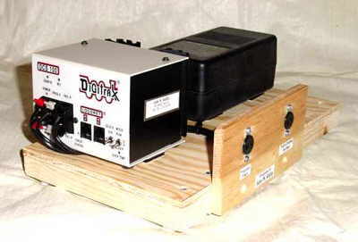
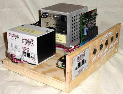
If you choose to build a DCC system board as shown in the photo in Rule 7 and as described on the NRMRC's Mounting DCC System Components web page, then you should solder a Cinch-Jones male connector to the single end of the power cable, again making sure the ribbed wire is soldered to the wide pin. This will plug into the appropriate jack on the system board, which in turn is wired so the wide pin connects to Rail A on the Booster. With this approach you don't have to check for the ribbed wire each time you set up the layout to ensure it is connected to Rail A, and you can be sure the wiring is correct.

The above ensures that track polarity will be correct for the tracks served by the Power Booster to which they are connected. However, if trains are to cross from one power district to another served by a different Booster another step must be taken. You must ensure the Boosters are in phase.

Checking Booster Phasing
To check for correct Booster phasing, remove all analog locomotives from the layout. Select the analog address 00 and set the speed of that address to 99 (maximum). You will note that the Track Status LED on the Boosters, which are normally orange, will now be either red or green. For all the Boosters to be in phase, the LEDs should be all red or all green. If you have a Booster where the LED is green when all the others are red, or vice-versa, you must change the phasing of that Booster.

Changing the phase of a Booster is done by changing the orientation of the LocoNet cable between the two Boosters. If the LocoNet cable is a straight through cable, replace it with a reversed cable, and vice-versa. Do this until all the Boosters are in phase — all the Track Status LEDs are the same color.

When the phase of the Boosters is set, be sure to return the analog address to speed 00, and dispatch the address from the throttle. Note that Boosters set up as Auto-Reverse Boosters do not need to be phased.

If these steps above are not done and the Boosters are not in phase, then a locomotive crossing from one power district to another with either cause a short circuit or the decoder could see double voltage with resulting damage to the decoder.


Top of Page

DCC Operations Page

DCC Home Page

NRMRC Home Page


Rule 4   Reversing Loops and Wyes Have Special Requirements

For reliability reasons, proper DCC practice is to separate the LocoNet for throttles, etc., from the LocoNet for the Power Boosters in order to minimize any corruption of data that may be caused by the Boosters "fighting" each other. On NTRAK layouts where there are no reversing loops or wyes, a single LocoNet will generally work fine, handling everything. When reversing loops and/or wyes are present then separate LocoNets are strongly recommended — as a minimum there should be a separate LocoNet between the Command Station and the reversing Booster(s). Further, there should be a ground wire (12 gauge preferred, 14 gauge minimum) between the ground terminals on all Power Boosters including the Command Station, and this ground wire should be connected to the power line ground at one point only.

Be sure to check the track and associated wiring to ensure full isolation at the reversing loop/wye entry and exit points. An easily overlooked item that can cause problems and frustration is properly isolated track, but someone has plugged in the NTRAK connectors below the module when they should not have been plugged. Take extra care with junction modules — see next rule.

If there are reversing loops and/or wyes in your NTRAK layout, take special care to do the digital design and setup correctly. Then test it thoroughly, and then test it again.


Top of Page

DCC Operations Page

DCC Home Page

NRMRC Home Page


Rule 5   Review Electrical Characteristics of All Modules in the Layout

This is extremely important, especially for modules that have not been in a Show with digital operations. Even though the owner may state categorically that he followed the NTRAK rules for wiring modules, this may not be sufficient to ensure trouble free digital operation — what works fine with DC will sometimes not work well with DCC.

Any module that does not meet NTRAK electrical standards as a minimum should not be used in a digital layout. Digital Masters should urge members of their club to follow the Recommended Practices for NTRAK Module Wiring whenever building new modules or upgrading existing modules.

Check especially for modules having control panels to handle local operation, as it can be possible with such panels to route both DC and DCC onto the same track, or to have a momentary joining of DC and DCC when a locomotive(s) bridges insulating gaps on the track. Also check modules with crossover tracks from one NTRAK main to another to be sure both rails are gapped and both tracks are completely isolated.

A number of clubs own "junction" modules that are used on the spine of larger, multi-section layouts to route trains to the various "Divisions" that make up such larger layouts. There is apparently no universal method of wiring these modules so they can fit in any configuration in a layout. Thus they must be modified to conform to the characteristics of the layout in which they are being used. Careful attention must be paid to these modules when using DCC.

Since there are NTRAK layouts where both DCC and Aristo throttles are used, some modules with passing sidings have been modified so that Aristo power can be fed from both directions independently thus allowing bi-directional operation. Be careful to ensure that the toggle switch that allows this break in power feed is set so that DCC power flows through.


Top of Page

DCC Operations Page

DCC Home Page

NRMRC Home Page


Rule 6   Like Oil and Water, Don't Mix DCC and DC (Analog)

Do not mix DCC and analog DC on different parts of the same track, nor switch trains from an analog DC track to DCC track, or back again. Do not have any shared or transitional trackage. Staging yards should be dedicated to analog DC or DCC, but not both. See the box below for a technical discussion on the interaction between DCC and analog DC.

There are two items to consider when a DC power section is bridged to a DCC power section, such as when a locomotive(s) crosses or shorts the gaps — protection of the DC power pack and protection of the DCC decoder.

Analog DC Power Pack
Most power packs put out less than 2A current whereas DCC Power Boosters put out 5A or more. Thus the DCC Booster will overwhelm the DC Power Pack, and, depending on the protection circuitry built into the DC Power Pack and the speed at which it activates to protect the Power Pack, the Power Pack output circuity could be destroyed. To minimize the risk of damage to a DC power pack connect a No. 1156 automotive bulb in series with one of the leads from the DC pack to the track.

DCC Decoders
The maximum safe voltage for a DCC decoder is 27 volts, but realistically anything over 20 volts will put the decoder at risk. You may be surprised just how many volts a DC power pack can put out at no load, especially older ones. Depending on the phasing of the DCC Booster and the polarity of the DC Power Pack a decoder could receive the sum of the Booster and Power Pack voltages, and be instantly destroyed when the wheels of the locomotive bridge the gaps between the DCC and analog DC track.

If a track does not have access to a staging yard because of the power system difference, do quick set-up and tear down of trains right on the mainlines. Be sure to keep trains running on the other tracks whenever one track is shut down for staging.

Consider placing physical blocks on DC/DCC crossover trackage to prevent movement from one system to the other. These could take several forms, such as a red-colored map tack or a blue- or orange-colored insertable sign placed in the middle of the tracks between ties at each side of the insulated gaps.

OK, so you have chosen to ignore this rule and operate both DC and DCC with a transition section between the two. Here's how you do it so you don't damage locomotives, power supplies, the layout or your reputation as an electrical/DCC guru (listed in decreasing order of importance)!

You will need a specially-wired module for the transition. Essentially you will have tracks with insulated joiners in both rails at each end of the module. Each track will have a DPDT center-off toggle switch which will be used to change the track power feed from DC to DCC, or vice-versa, after all the locomotives and any lighted cars have stopped entirely in the transition module.

Construct or modify an NTRAK module as follows:

  • Decide on the length of the transition module. It must be long enough to contain at least your longest set of MU consisted locomotives. If you run lighted passenger cars the entire train including locomotives and cars must be able to fit on the transition module or a short will occur as each axle passes over the joint with the adjacent module. At best the train will stop-and-start as the Power Booster and/or DC power pack shuts down with each short. At worst the DC power pack and/or decoders in the locomotives could be damaged or destroyed.

  • Purchase the needed number of DPDT center-off toggle switches. Be sure the rated current capacity of the switches exceeds the highest amperage required, usually that of the DCC Booster. (For a toggle switch in a model railroad application, current is more important than voltage.)

  • A DPDT switch has two rows of three terminals, one row on each side of the switch. Wire a DPDT toggle switch for each track as follows:

  • Connect wires from the center terminals of the DPDT switch to the two rails. Note which side of the switch goes to the front rail.

  • Connect wires from the NTRAK connectors at one end of the module to the two terminals at one end of the DPDT switch. (Leave a little slack in the wires for flexibility in mounting the switches.) Be sure the wire from the NTRAK connector wide blade goes to the switch terminal on the same side as the wire to the front rail.

  • Repeat for the NTRAK connector at the other end of the module. Again be careful to ensure the wire from the connector wide blade goes to the switch terminal on the same side as the wire to the front rail.

  • Mount the DPDT switches to the module in a convenient location. Orient them so that when the toggle is thrown to the left, the track is powered from the left end of the module. This makes it easy to set the switch direction depending on which way the train is traveling.

Note that DCC-equipped locomotives must have analog conversion turned on in their configuration (CV29) for this transition from DC-to-DCC, or vice-versa, to work.


Top of Page

DCC Operations Page

DCC Home Page

NRMRC Home Page


Rule 7   Use Power Supplies Matched to the Power Boosters

Do not use standard DC power packs of any type to supply Power Boosters. Always ensure the power supply is capable of producing at least the rated power output of the Power Booster it is supplying.

The NRMRC uses Digitrax PS515 power supplies for Command Stations and Boosters of 5 Amps or less, and Loy's Toys power supplies for Command Stations and Boosters of 8A or more. The photographs show two of the NRMRC's Command Station/Boosters using both types of power supply.

Board 03

Board 13

Digitrax DCS100 Command Station/Booster and Digitrax PS515 Power Supply. The NRMRC uses this particular board for programming locomotive decoders, and as a spare to the main Command Station at right.

Digitrax DCS200 Command Station, Loy's Toys 16V 10A Power Supply, Digitrax PM4 Power Manager and Digitrax UP3 Universal Panel. A small Radio Shack 12V transformer for the PM4 is mounted inside the Loy's Toys case.


Top of Page

DCC Operations Page

DCC Home Page

NRMRC Home Page


Rule 8   Only One Command Station Can Command

Be sure there is only one Command Station controlling the entire layout. Any other DCS100 or DB150 Command Station/Power Boosters used on the layout must be set to Booster-only mode. This is done by setting OPSW #2 to closed ("c") — see Table below.

For Larger Layouts
For large layouts and layouts with more than one booster it is recommended that the Command Station not be connected to the track. Experience has shown that if the Command Station stays away from all the shorts, etc., that occur on the layout that there will be fewer problems, which makes for a better session. This is a Digitrax recommendation.

For a large layout the Command Station should also be powered from an Uninterruptible Power Supply (UPS). This will keep any power spikes and other power line noise out of the system.

A total reset of the Command Station to its factory default setting should be carried out at the start of each Show. This clears the internal memory of the Command Station of things like consists that may be left over from a previous show or operating session. This is done by setting OPSW #39 to "closed" using the procedure in the following table.

Once the Command Station reset is done the following settings are recommended for normal show operations:

OPSW #

Set To

Function

OPSW #02

Closed

Disable Command Station function (when necessary).

  • OPSW #02 must be closed on all DCS100, DCS200 and DB150 units used in the layout, except the one that is the "real" Command Station.

  • Instead of closing OPSW #02 on a DB150 you can connect wires between CONFIG A and the GROUND terminals on DB150 units that are not the "real" Command Station. If the DB150 is to be an auto-reversing booster, connect wires between both CONFIG A, CONFIG B and GROUND.

OPSW #03

Thrown

Sets Booster as Non Auto-Reversing.

  • OPSW #03 must be closed if the Booster is to be auto-reversing.

  • Instead of closing OPSW #03 on a DB150 you can connect a wire between CONFIG B and the GROUND terminals.

OPSW #05

Closed

For Command Station only. Recommended by Digitrax.

OPSW #18

Closed

Extends short circuit shut down time from 1/8 to 1/2 second.

  • This helps when momentary shorts occur such as when wheels bridge the gap between rails at turnouts and crossings.

  • This is strongly recommended when Boosters feed through a PM42 Power Manager.

OPSW #20

Closed

Disable Address 00 (analog stretching for conventional locomotives).

  • The use of address 00 can cause several different problems, especially if the DCC system is heavily loaded, or if address 00 is dispatched from the system with a speed other than 00.

    Note: Do not disable Analog operation until all Boosters have been phased then be sure address 00 is set to 00 speed and dispatched from the system.

OPSW #25

Closed

Disables aliasing. Aliasing should not be used at Train Shows.

  • Aliasing adds a level of complexity that you don't really need. If a locomotive has a decoder set for 2-digit addressing, use it. Do the same for locomotives with decoders set for 4-digit addressing.

OPSW #44

Closed

Expands system capacity (slot refresh area) to 120 locomotives.

  • When you fill up all the system slots any attempt to select another locomotive will result in the right-hand throttle display showing "FF". Expanding the number of slots from 22 to 120 will significantly reduce the chance of encountering an "all slots full" condition. Careful dispatching of locomotives from the system when they are finished operating will ensure slots remain free.

  • This applies to DCS100 and DCS200 only. Not applicable for DCS050 or DB150.

 
Procedure to Set OPSW Switches:

DT100/DT100R Throttle

DT300/DT300R Throttle

DT400/DT400R Throttle

1.

Move right toggle switch on front of Command Station to OP position.

2.

Disconnect LocoNet from Command Station and connect DT100/R to LocoNet port.

3.

Press MODE/DISP to enter Switch mode.

4.

Use throttle knobs to dial up desired option switch. OpSw # will appear in display left side and either "c" or "t" in display right side.

5.

To change state of OPSW press L Reverse key for thrown (t) or R reverse key for closed (c).

6.

Repeat steps 4 and 5 until all desired OPSW have been set.

7.

Move Command Station mode switch to RUN.
 

1.

Move right toggle switch on front of Command Station to OP position.

2.

Disconnect LocoNet from Command Station and connect DT300/R to LocoNet port.

3.

Press MODE to enter Switch (Sw) mode.
 

4.

Use throttle knobs to dial up desired option switch. OpSw # will appear in display left side and either "c" or "t" in display right side.

5.

To change state of OPSW press L Reverse key for thrown (t) or R reverse key for closed (c).

6.

Repeat steps 4 and 5 until all desired OPSW have been set.

7.

Move Command Station mode switch to RUN.
 

1.

Move right toggle switch on front of Command Station to OP position.

2.

Disconnect LocoNet from Command Station and connect DT400/R to LocoNet port.

3.

Press SWCH to enter switch mode.
 

4.

Use numeric keypad to enter desired OpSw number. The OpSw number is displayed on text line along with "c" or "t."

5.

Press OPTN t to move OpSw to "thrown" position or CLOC c to move it to "closed" position.

6.

Repeat steps 4 and 5 until all desired OPSW have been set.

7.

Move Command Station mode switch to RUN, and press EXIT or FUNC on throttle.

If resetting OPSW #39 with a DB150 in step 7 do the following: Move Mode switch to SLEEP, then move Mode switch to RUN.

Once programming is complete, set the Command Station to the "sleep" mode then reconnect the normal LocoNet cables.

If, during the Show, locomotive response to the throttle becomes sluggish, or if locomotives will not switch direction on command, or if the top locomotive in a consist seems to respond faster than the other units, do the following:

  • Check analog address "00" to ensure analog speed is set to "00".

  • Again perform a reset of the Command Station (OPSW #39) to clear everything out of its internal memory. Reset the OPSW as described above.

It is good operating practice and mandatory for Train Shows when a locomotive or locomotive consist is removed from the layout to also remove it from the DCC system — break down the consist to its individual locomotives and dispatch each locomotive from the system. This frees up slot memory for additional new locomotives.

Be sure to power up the Command Station first, before any other Boosters/Command Stations. This will allow the Command Station to establish itself as the master.


Top of Page

DCC Operations Page

DCC Home Page

NRMRC Home Page


Rule 9   Radio Throttles are Better than IR Throttles

DTxxxR radio throttles are the preferred method for control of NTRAK layouts, by far.

Radio signals are omni-directional, which means you can point the throttle in almost any direction and still have successful reception. This is also why you generally need only one UR91 for most layouts. Where building characteristics (HVAC ducts, other electrical interference, etc.) affect radio reception, a second receiver almost always takes care of the problem. A third UR91 might be needed on very large layouts. Radio signals are functional to about 300 feet.

DTxxxIR infrared throttles, like television and other remote controls, are line-of-sight devices. You must remember to always point the throttle toward the UR90 or UR91 receiver. If you cannot see the receiver from your location (turning around doesn't count), your commands will not be received. If you hold the throttle too low, the layout may block the signal from reaching the receiver. Someone walking between you and the receiver can block the signal.

For successful operation of IR throttles with an NTRAK layout, several IR receivers would be required to give full coverage of the layout. The exact number would depend on the size and shape of the layout. IR receivers must be mounted high (use the radio tower) to give a clear line-of-sight between the DTxxxIR throttles and the receivers.

While IR remote control signals may reflect off walls at home (flat wall surface in a small room), this is usually not the case for NTRAK layouts at shows. Line-of-sight must be assured. It is easier and more reliable to use radio throttles. IR throttles will definitely not work outdoors.


Top of Page

DCC Operations Page

DCC Home Page

NRMRC Home Page


Rule 10   Be a Good Neighbor to Other DCC Layouts at a Train Show

Two or more DCC layouts located side-by-side at a Train Show can operate with up to about 10 DTxxxR throttles each. The exact number of throttles depend on how much the throttles are used to change speed, direction and lights. Operators that constantly throttle up and down, change direction, alter lights, etc., can degrade response and ultimately limit capacity to as few as 7 or 8 throttles.

Note that adding more UR91 receivers does not increase the number of DTxxxR throttles that can be handled — this only improves radio reception. To increase throttles you must obtain throttles and receivers that operate on a second frequency (a Digitrax special order item).

There should be no interference between side-by-side DCC layouts at a Train Show, and each can have locomotives with the same address. The reason there will be no interference is the unique way Digitrax uses to identify LocoNet systems by number. When a DTxxx throttle sends a message it is to a LocoNet system number. The Digital Masters for the layouts should meet to assign LocoNet system numbers to each layout, then ensure the Command Station is set to that number. The LocoNet ID range is 0 to 7, with 0 as the default.

To change the LocoNet ID you require a DTxxxR throttle with a battery in it, and all UR91/UR90 receivers that will be part of the layout should be connected to LocoNet when the ID change is made. Follow these steps:


DT100/DT100R Throttle

DT300/DT300R Throttle

DT400/DT400R Throttle

1.

Disconnect the DT100/R from LocoNet.

2.

Press and hold MODE/DISP on the DT100/R and plug back into LocoNet. Release MODE/DISP after plugging in the throttle.

3.

The DT100/R will display the current LocoNet ID "Ir:0n" or "rA:0n," where "n" is the current LocoNet ID. Use the right throttle knob to change the ID, which can be 0 to 7.
 

4.

Press SEL/SET to set the system to the new LocoNet ID

5.

The DT100/R used to change the ID will automatically log on to the new LocoNet ID.

1.

Disconnect the DT300/R from LocoNet.

2.

Press and hold MODE on the DT300/R and plug back into LocoNet. Release MODE after plugging in the throttle.
 

3.

The DT300/R will display the current LocoNet ID "Ir:0n" or "rA:0n," where "n" is the current LocoNet ID. Use the right throttle knob to change the ID, which can be 0 to 7.
 

4.

Press SEL to set the system to the new LocoNet ID.

5.

The DT300/R used to change the ID will automatically log on to the new LocoNet ID.

1.

Disconnect the DT400/R from LocoNet.

2.

Press and hold EDIT on the DT400/R and plug back into LocoNet. Release EDIT after plugging in the throttle.
 

3.

The DT400/R will display E1 in the Mode indicator and the current LocoNet ID "Ir:0n" or "rA:0n", where "n" is the current LocoNet ID. Use the right throttle knob to change the ID, which can be 0 – 7.

4.

Press ENTER to set the system to the new LocoNet ID.

5.

The DT400/R used to change the ID will automatically log on to the new LocoNet ID.

Unplug and reconnect any other DT series throttles that will be used on this system so they can log on to the new LocoNet ID number and be able to operate on the system.

If a new UR90 or UR91 is added to the system the IDs must be re-synchronized in all the UR90s and UR91s using this procedure.


Top of Page

DCC Operations Page

DCC Home Page

NRMRC Home Page


Rule 11   To Analog or Not to Analog, That is the Question!

Digitrax and other DCC systems can operate analog (DC) locomotives on Address 00. This was designed into the system so purchasers of DCC systems could operate their existing locomotives prior to installation of a decoder for digital operation. Analog operation is accomplished by stretching pulses to simulate a variable voltage power pack. The use of the stretched pulses can have various effects on the DCC system, especially when under a fairly heavy load, causing undesirable results, such as delays in responding to commands from DTxxxR radio throttles.

Do not use Address 00 for analog locomotives when operating NTRAK layouts, and be sure that the speed of Address 00 is set to zero. Consider disabling analog capability entirely by closing OPSW #20 on the Command Station. Refer to information in Rule 8 for how to do this.


Top of Page

DCC Operations Page

DCC Home Page

NRMRC Home Page


Rule 12   Power Each UR91 Radio and UR90 IR Receiver Individually

Be sure that each UR91 Radio Receiver and/or UR90 IR Receiver is equipped with its own wall-wart power supply, and the wall-wart is plugged into working 120 volts. Either receiver places a heavy current draw on LocoNet, and enough of them, coupled with UT-type throttles will cause problems with LocoNet if there is not supplemental power.

On the radio tower, the 12-volt points on the UR91 and the UP3 are connected together, then the wall-wart is plugged into one of them.


Top of Page

DCC Operations Page

DCC Home Page

NRMRC Home Page


Rule 13   Power Each UP3/UP5 when UT1 and/or UT2 Throttles are Used

Digitrax UT1 and UT2 throttles do not have batteries and therefore can load the LocoNet if used in sufficient numbers. The LocoNet voltage drops with each UT1 and UT2, and enough of them can lower the LocoNet voltage to the point where LocoNet goes to idle. Connecting the UP3/UP5s to track power or to auxiliary power through a wall-wart supplements the LocoNet power provided by the Command Station.

It may not be necessary to power all UP3/UP5s if the UT1 and UT2 throttles are used only at a specific location, such as a yard. In such a case, the UP3/UP5s at that location(s) should be powered.

It is generally not necessary to worry about powering UP3/UP5s for DT-type radio or IR throttles, as these will have batteries in them for tetherless operation, and are normally only plugged into LocoNet for selecting/dispatching locomotives.


Top of Page

DCC Operations Page

DCC Home Page

NRMRC Home Page


Rule 14   Old Batteries Never Die, They Just Lose Their Charge

Always use newly purchased, fresh batteries in throttles on NTRAK layouts. Be sure to purchase these batteries from stores that sell lots of batteries to ensure the new batteries are fresh, and not nearing the end of their shelf life.

The successful operation of the DTxxxR and DTxxxIR throttles in tetherless mode requires a battery mounted in each throttle to provide power to the throttle. While these throttles do provide a low-battery alarm, the signal may be missed by the operator, especially in a noisy environment. Also, internal resistance of the battery may cause problems as the voltage drops, even though it has not dropped far enough to trigger the low-battery alarm. Whenever problems are encountered with a radio throttle you should suspect the battery. Plug the throttle into LocoNet and replace the battery.

Note: Even a new battery can have sufficient internal resistance that will prevent proper operation of a throttle, but this is rare. Before presuming a throttle is at fault, try a second new battery.


Top of Page

DCC Operations Page

DCC Home Page

NRMRC Home Page


Rule 15   Clean the Track and Clean the Wheels

This is good practice whether DC or DCC. The important message in this rule is to be sure that the track has dried from any liquid track cleaner (such as Formula 409 or Fantastik; Goo Gone is not recommended for cleaning track) and that any residue has been removed. If trains are run while the track is still wet, then the train will spread any dirt that is coming off wheels or the residue of the cleaner all over the layout. Then you have a real problem.

There are two ways to clean the track — use track cleaning cars such as Aztec or two Centerline cars (with a wet cloth on the front roller and a dry cloth on the rear roller), or wipe the track with a wet rag then follow up with a dry rag. Clean wheel sets with a paper towel laid on a track and wetted with Formula 409 or Fantastik. Roll a car back and forth and the gunk will come off. For locomotives, do one truck at a time on the towel with power applied so the wheels are turning or use the Minitrix Locomotive Wheel Cleaner.


Top of Page

DCC Operations Page

DCC Home Page

NRMRC Home Page


Rule 16   Test the Layout Following Setup: Coin Test

It is extremely important for the proper and safe operation of the layout that a short circuit anywhere on the layout cause a device (PM42 or Booster) to shut down virtually immediately. The best way to assure this is to conduct a "coin" test. This test is very simple and requires only a quarter (25 cents) to perform. Failure to perform this test and fix any problems encountered could result in damage or destruction of electronic equipment, rolling stock and/or locomotives, and unsafe conditions on the layout.

For each track in each power district, place a coin across the track (to create a short circuit) close to the location of the main power feed to the track. The Booster or PM42 should shut down virtually instantaneously. Repeat the test at each end of the Power District. If the Booster or PM42 does not shut down within less than one second, then you either need to make the Power District smaller, run a parallel power feeder cable, and/or check NTRAK wiring connections until the source of the high resistance is found. Continue testing and adjusting until the coin test produces a shutdown condition.

When carrying out the Coin Test, leave the coin on the track only long enough to determine whether the Booster or PM42 shuts down, then remove it. If resistance is such that the Booster or PM42 does not trip the coin will get warm during the test, and get hotter the longer it is on the track causing the short circuit. You can be burned!


Top of Page

DCC Operations Page

DCC Home Page

NRMRC Home Page


Rule 17   Test the Layout Following Setup: Stress Test

Always test everything before beginning normal operations. Run as many single locomotives as possible over the layout simultaneously. Some problems can only be found with high traffic density.

A problem that can easily crop up is the momentary shorting of metal wheels across the narrow gap between the rails at an insulated frog turnout or crossing, which causes a momentary pause as the Booster or PM42 detects the short circuit, shuts down then restarts as the wheels pass by. This is repeated for each metal wheel set shorting at the frog. The quick remedy at a train show is to either coat the tip of the frog with clear nail polish (which may have to be re-applied as it wears off with train traffic) or to apply a small piece of thin tape to the end of the frog where the short occurs.


Top of Page

DCC Operations Page

DCC Home Page

NRMRC Home Page


Rule 18   Provide a Means of Programming Locomotives

Always have some way to program locomotives. Someone may have just installed a decoder, or there may be a need to check the values of CVs in a decoder to diagnose a problem. There are two ways: use a programming track with a DCS100 Command Station and a DTxxx throttle, or use a notebook computer with a PR1 or Decoder Pro programmer. Which one is really your choice. The NRMRC mostly uses the programming track and throttle.

How do you decide which method to use?

  • If you have many visitors that will run their locomotives on the layout, or if your are dispatching the DCC portion of the layout, or if you will be programming speed tables and other special effects then the computer + PR1 or Decoder Pro programmer is the way to go.

  • For information on setting up the PR1 programmer, go to the page on Installing and Setting Up the PR1 Programmer.

    For information on downloading and setting up DecoderPro go to the JMRI group at http://jmri.sourceforge.net/DecoderPro.

  • If you are mostly using home locomotives and will only be programming the address and CV29, then use the programming track with a DTxxx throttle.


For Larger Layouts
In order to manage Command Station memory slots and keep locomotives with identical addresses from interfering with each other, there should be a programming station set up, using the PR1 or Decoder Pro, to program every locomotive that will be used on the layout, and then to release (dispatch) those addresses when the locomotives finish their run.

In order to run on the layout an operator takes the locomotive(s) he/she will use to the programming station, where he/she will be assigned an address(es) and the locomotive(s) programmed to that address(es). A record is kept of the name of the operator and the address(es) assigned. When the operator is finished running the locomotives he/she returns to the programming station to release the address(es) and have the locomotives programmed back to their original address.

Unless more than about 100 addresses are expected to be in use on the layout at any given time, 2-digit addresses should be used for these large layouts.


Top of Page

DCC Operations Page

DCC Home Page

NRMRC Home Page


Rule 19   Identify Ownership of All Digital Equipment

The purchase of Digital Command Control equipment represents a significant investment on the part of the Club or the individual owner. To ensure the equipment is returned to its rightful owner after the Show is over, all digital components and equipment should be labeled with the owner's name or some other well-known clearly identifiable marking. A return address label applied to the item is a simple and adequate means of identification.

Many clubs establish a DCC ownership policy. Usually the Club provides the DCC Command Station, Boosters, UR90/UR91, Universal Panels and LocoNet cables. Individual members are expected to provide their own DT-type throttles.


Top of Page

DCC Operations Page

DCC Home Page

NRMRC Home Page

Track Spacer

Home page:

http://trainweb.org/nrmrc/

URL This Page:

http://trainweb.org/nrmrc/dcc/rules.html

Last Updated:

May 3, 2010

Webmaster:

John M. Wallis (Email to John)

/This page and all contents are Copyright 1997–2007 by the North Raleigh Model Railroad Club.
(The NRMRC is a Non Profit Corporation incorporated in North Carolina.)
The various logos and heralds shown here are the property of their respective organizations.

You are passenger no.

Counter

   Digits