 20 Feb 00
 20 Feb 00
 17 Feb 00
 17 Feb 00
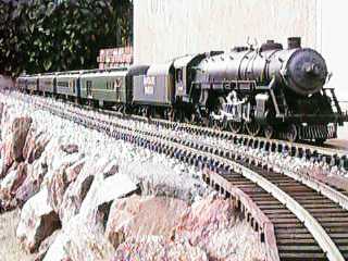 The
heavyweight passenger car came into existence after the turn of the
century. It's design evolved from the recognized inadequacies of
the older wooden coaches.
Wooden coaches served the railroads well for many years, but it's not clear that they served the passengers all that well. Wooden coaches had significant passenger safety and comfort problems. The cars were fairly light so that older and smaller engines could handle them. However from their lightness, came serious problems. They didn't ride well, especially as speeds increased past 20 or 30 mph and they weren't very strong. The wooden construction wasn't sturdy enough to hold up in a wreck so that cars often broke up and splintered badly even in minor accidents. The hot coals from the stoves used for heating were often scattered among kindling that was formally the structure of the car and started horrible fires. The cars had no compressive strength so that cars often "telescoped" in a wreck with one car simply plowing through another, often killing everybody in the telescoped car.
Wooden cars rode pretty poorly. After a day of bumping and swaying, one's body could hurt all over from trying to correct for the car's movement. The early railroads provided a smoother ride than a stagecoach, but it was still much worse than an automobile on a fair road. This is one of the reasons that the railroads lost short haul passenger traffic to automobiles.
Steel cars came into being to service the long haul and commuter markets. First the cars just had steel frames, but eventually, the whole car was made of steel and vestibules were added to the cars. This had the desirable effect of eliminating the end platforms allowing safer and more comfortable car to car access. Much more important is that the vestibules were structurally integrated into the car bodies so that the cars did not tend to telescope in a wreck. The cars would often derail in accordion fashion instead but at least they wouldn't be crushed. Cars could roll over completely and still retain something like their original shape. Low pressure steam heat replaced coal heat and electric light replaced oil lamps, which with the elimination of all of that wood, sharply reduced the tendency for fires to start after a wreck.
The cars were called "heavyweights" for a very good reason. Besides the steel used in construction, the cars often had a six inch slab of concrete cast into their floors. This added a lot of sprung mass which made the car bodies tend to resist the tendency to bump and bounce over track irregularities. This resulted in significantly improved riding qualities, especially at the high speeds often used in the late steam era. Only significant improvements in suspensions allows the newer and lighter streamlined cars to ride better.
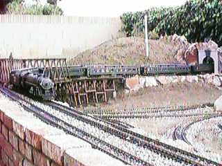 Aristo's model of
the standard heavyweight cars is based on standard steel car
construction practice. It is a model of an 72' car so the model is
very large, 33" across the stock couplers and 30" across the
vestibules. It needs large radius track to operate properly, 4 foot
radius is the minimum practical, much more is much better.
[ Top ]
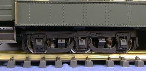 Older cars were made
with either four or six wheel trucks depending on what was used on
the prototype cars for the particular railroad modeled. Six wheel
trucks were used to reduce wheel loading for these typically very
heavy cars. My first five heavyweights came with six wheel trucks
even though the Aristo catalog at the time indicated that some of
them should have had four wheel trucks.
The center axle is hard mounted on the truck frame. Each end axle is sprung. The end axle springs collapse about 1/6" when the center wheel touches the track. This allows the truck to flex somewhat to handle track irregularities. The center axle is also given the ability to slop laterally so that the whole truck can make it though turns better. Most of the weight of the cars is carried by the center axle. Therefore, the bushing on the center axles tends to wear faster than the end axles.
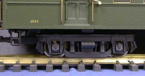 When the Pullman finally
arrived, it came riding on four wheel trucks like this one. Pullman
cars were usually extra heavy to allow the sleeping first class
passengers a good night's sleep so they usually rode on six wheel
trucks. These trucks have a shorter wheelbase and have considerably
less drag than the six wheel trucks. Trucks like these were usually
used on the "lighter" of the heavyweight cars such as this RPO.
This car originally came with six wheel trucks but has been back
fitted with 4 wheel trucks.
The four wheel trucks are sprung to allow the wheels to follow
bad track. However, the springs hardly collapse at all under the
weight of the car so that truck acts much like it had an unsprung
truck. A strong force will push a wheel up, but there is no
downward movement possible. Softer springs, like the ones that come
on the diesel engine trucks are too soft and collapse completely.
This problem is aggravated somewhat because the journal boxes
sometimes hang up and stick. Treatment with graphite on the journal
box slides will free them up to allow them to move under minimum
force. The six wheel truck journal boxes can hang up as well, but
the truck castings seem to be a little looser and the journal boxes
don't tend to hang up as much.
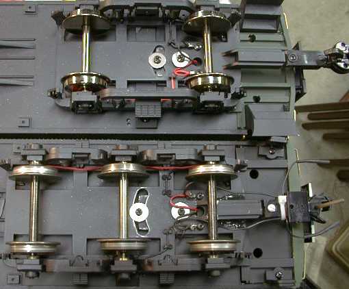 Replacement
four and six wheel trucks are available in pairs as separate items
and they can be changed out on any car. The spacing between the
pivot hole and the curved guide slot on the two truck types is
different so that part of the bolster must be moved. There are
holes drilled in the floor to allow the bolster to be moved to its
new position, see below.
The car with the six wheel truck has had its coupler moved as described below. This brings the cars much closer together so that the bolsters nearly touch. It also has power connection wires and connections installed to allow track power to be picked up down the entire length of the train, see my Power Connector Tips page for details on the connection method.
When this photo was taken, the car with the four wheel truck still has the stock Aristo coupler in the stock position. This got fixed immediately after the photo session.
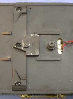 The bolster
for a six wheel truck mounts with three screws and it can be
removed and moved closer to the pivot to allow a four wheel truck
to be mounted. However, it doesn't fit the way it is and needs some
modification.
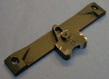 A little grinding
on the bolster creates a relief that allows it to clear the truck
pivot. It should be ground and fitted until the bolster runs up
hard against the two straight ridges next to the pivot.
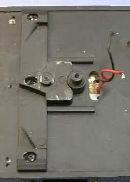 When the bolster
is remounted it may be necessary to redrill the holes for the
mounting screws. There are small clearances cast into the car
floor, but sometimes they are too small to accept a screw.
Older production six wheel trucks had a nasty reputation for derailing on LGB 1600 turnouts. Newer production cars seem to do much better. There appear to be three contributing factors that impact how the cars track through turnouts.
I've run a lot of tests on new cars with Kadee couplers and modified turnouts . The heavyweight cars with six wheel trucks work just as well as regular freight cars in LGB 1600 turnouts, 4' radius curves, "S" curves and "S" curves made from LGB 1600 turnouts.
The Aristo Heavyweight is a VERY long car. Because of this, it is much more sensitive to track irregularities than other cars. Even though the trucks are sprung and flexible, the trucks MUST be allowed to rock with respect the carbody so that each truck can follow wavy track without transferring forces through the carbody to the other truck. It is necessary to loosen all four truck mounting screws about two full turns. If you don't do this, expect derailments on anything but perfectly level track.
Cars with six wheel trucks exhibit considerably more drag in turns than cars with four wheel trucks. This is due to flange drag even though the center axle has additional lateral play. Drag increases greatly with decreasing radius and the car won't run on less than 4' radius at all. However, my railroad has many curves at 4' radius and except for the drag, the cars handle it fine. I did some roll tests with cars with four and six wheel trucks. The cars with four wheel trucks roll nearly as well as a normal freight car on both 4' and 5' radius curves, it gets down the grade and almost around a full half turn before stopping. The car with six wheel trucks will roll down a 1.6% grade and about half way into the first 5' turn. On the 4' turn, it grinds to a stop as soon as it hits the curve. It really does act like somebody big holed the brakes.
The center axle can be removed completely and the car will still work properly, although the car might sit just a little lower as the entire weight of the car is placed on the sprung axles. This tends to reduce the drag a little, but the impact is not great. The major part of the drag seems to be coming from the extra long wheelbase of the end axles.
My Aristo Pacific pulls four heavyweights, all with six wheel trucks, on a 1.6% grade with a 4' radius turn, but it can't handle five cars on the same turn. On a 5' radius turn at the same grade, the Pacific handles five cars some considerable difficulty. Even at a 5' radius, the cars have much more drag than on a straight track. If you can afford the room, the cars will both run and look better on 10' radius turns and a minimum of a #6 turnout (an LGB 1600 turnout is not quite a #4).
I have converted the remaining four of my six heavyweights to four wheel trucks just to obtain an operational advantage even though I like the look of the six wheel trucks much better. Now the Pacific can deal with all six cars even on the 4' radius turn without appreciably slowing on the turns. The grade is a now the main problem, the Pacific is at its limit with these six cars even on the straight parts of the grade.
The minimize the drag, especially with six wheel trucks, use nylon washers to shim the outer two axles on the trucks and be sure that the axle bearings are adequately lubricated. In this case, oil is preferred because it provides lower bearing friction than graphite. I use LGB 20019 oil as it seems to work better than any other that I have used. DO NOT shim the center axle. It needs to be able to slop sideways or the trucks will not make it though anything but a very broad curve.
[ Top ]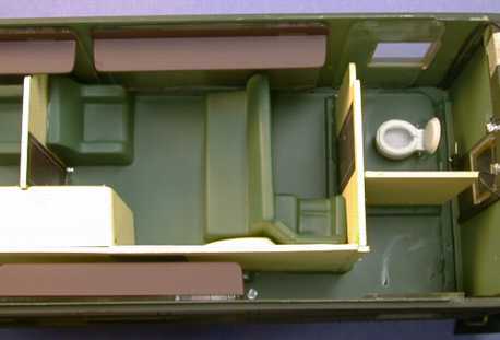 Most of the
heavyweight cars come with some kind of interior detail. This photo
is one end of the Pullman car. There are a total of six
compartments like the one shown. Notice that the wall of the
lavatory blocks the end door from opening. The RPO has no interior,
nor does the baggage half of the combine. The diner has tables with
a working light on each table, although the lamp is fairly dim and
can't really be seen in daylight.
[ Top ]
Kadee makes a special package for truck mounting their couplers on Aristo heavyweights, but I found that the special kit is not necessary. A Kadee #831 mounts fine if about 1/8" of the back of the coupler box is ground off. The box will then mount in the original screw hole with the original screw and be at exactly the right height.
Body mounting couplers on heavyweights is probably not a good idea UNLESS your track plan is completely devoid of any kind of S curve and has a very large minimum radius.
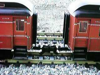 As
delivered, the car to car spacing of the heavyweights leaves a lot
to be desired. This huge spacing doesn't appear to be
necessary.
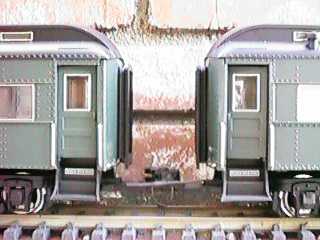 With the Kadee
#831 truck mounted coupler, the spacing comes a little closer, but
it is still way too wide.
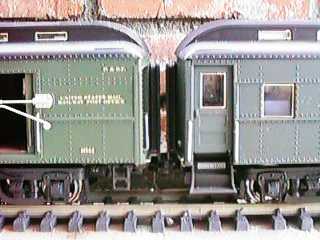 In a 1:1 scale
configuration, the striker plates are held tightly together by
springs to seal the diaphragms together and keep out the weather.
The striker plate is the frame around the end of the diaphragm. In
the model, the cars can be brought together so that the striker
plates nearly touch, but it takes a little bashing to accomplish
it. The method that I have chosen is to cut the existing coupler
tang off at the base and reposition it back by about 0.8" to 0.9""
and then to reattach it with epoxy. These dimensions apply to "G"
scale Kadee couplers, with #1 scale couplers, the positions will be
a little different as the knuckle opening is somewhat smaller.
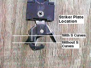 Depending on
if you have S curves or not, the coupler mounting position can be a
little different. When the coupler is remounted to handle S curves
and you sight down the striker plate from the top of the car, the
very deepest part of the coupler opening should line up with the
striker plate. This leaves enough clearance so that the striker
plates will just clear each other when backing through S curves. If
you don't have S curves and want a closer spacing, then the striker
plate should line up with the approximate center of the coupler
opening. In this case, the striker plates will actually touch
during backing moves and just clear each other in forward moves on
4' radius curves.
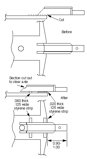 My method is to cut the
tang where indicated with a razor saw and then reattach it with
epoxy in its new location. Note that unlike the drawing, the wire
clearance hole is slightly off center. Do not center the end of the
tang with respect to this hole. Center the end of the tang between
the lugs to either side. The tang should extend 0.9" to 1" past the
body of the truck. If you have S curves, you should use the 1"
dimension. In the new position of the coupler mounting tang, it
will interfere with the nearest axle when the springs for that axle
are compressed. After the epoxy has set, remove the wheelset and
grind off some of the back end of the tang to allow the axle to
clear it. On the newer cars, make sure that you put the wheelset
back in the same way it came out or you will pick up power off the
wrong rail and cause a short circuit. With the couplers at the
right height, they will just clear the two extensions that hang
down from the striker plates.
A photo of the before and after state of the trucks can be seen in the section above concerning tracking and drag.
The trucks are made of ABS plastic to which most epoxies do not adhere very well. The joint obtained is mostly mechanical so get a good bond, the surfaces have to be roughed up to give the epoxy something to hang on to. You can epoxy to the paint and the epoxy will adhere to the paint fairly well, but then you rely on the paint adhering to the plastic. At least with the paint that Aristo uses, this seems to work OK. Further, I usually drill small holes near the joint and push epoxy into the holes with a toothpick and then I make sure that a fillet of epoxy covers the holes. This allows the epoxy to "pin" itself in place. This only works with filled epoxies that have a structural enhancer mixed in them. I use Devcon Plastic Steel two part epoxy, its very strong and it hardens black in color. If you want a white joint, then there is a ceramic filled version that is also very strong. Devcon Plastic Welder epoxy is OK, but on ABS it works only marginally well and it isn't as strong as the other two.
Most filled epoxies are strong but brittle. You need to make sure that you use a fairly large fillet and cover a large surface area adjoining the fillet. If you do find that the tang isn't in the right place after the epoxy has set, you can break the joint, grind it off and start over. Aristo uses sufficiently thick structures so that the truck body and tang are stronger than the epoxy.
The same modification can be made on four wheel trucks since the all the dimensions at the coupler end of the truck are the same.
 Bruce Jahn writes
"...you might save some folks some confusion by adding that if they
wish to use the #1 couplers, they merely have to lay the 821's on
top the tang after removing the Aristo coupler, drill the two holes
through the tang lined up with the coupler pockets, and attach them
right on top of the tang with the long 2-56's provided. Although
the cars will still be about a fat 1/4" apart on the straight, it
is quite an improvement, and doesn't involve any cutting or epoxy
mixing. If one wants to get the cars even closer, all that is
needed is to cut away about 1/8" of the step in the Aristo coupler
tang in order to move the couplers closer to the center of the car
and the cars will be just barely touching when on a 1600
curve."
Aristo heavyweights have interior lighting that is powered from the track. The power pickups have been modified on the new cars.
The older cars used cast wheel assemblies. Each wheel and half axle were cast as one piece and the two pieces were joined with a plastic insulator placed at mid-axle. This allows power to be transferred from the wheel to the bearing for power pickup on each wheel.
The new cars use CNC machined wheels. Only one wheel is insulated from the solid axle so that power pickup via the bearings is possible on only ONE wheel on each axle. This same approach used on the new streamliner cars.
If you try to substitute a new wheelset on an old car, you will get dead shorts through the axles. To make this work, you will have to rewire the trucks to bypass the bearings on one end of each axle. Aristo's standard wiring method is to use one wheel on each truck to contact each rail. This minimizes pickup problems over turnouts. six wheel trucks pick up power on 3 wheels on each truck, the end axles contact one rail and the center axle contacts the other.
You might think that this would produce worse power pickup than the older setup, but actually it works out better than before. Aristo cast wheels get dirty very easily so that power pickup at the wheel tread is flaky. The newer wheels do not seem to collect nearly as much crud as the older wheels, so even with half the wheels doing the work, the overall result is better.
If you find that the lighting flickers too much, check for continuity at each wheel. Sometimes one or more of the wires will break off the lug that connects to the wheel bearing. If yours have broken, try to replace or reroute the wire so that the movement of the bearing does not put undue stress on the joint.
Also, if the bearings have worn too much and become elongated, they can be replaced or rotated 180 degrees to put a new bearing surface at the top. If you do rotate them, be careful as the solder lug will try to rotate as well and the wire will get broken.
In the photos above, you can barely see an extra wire leading between the cars. I wire power pickups together all along the train (and to the engine too) so that power pickup is very good even on really dirty track. See my Power Connector Tips page for a little more information on the method that I use.
[ Top ]The standard heavyweight is lit with four #53 14 volt bayonet base bulbs (Radio Shack 272-1117) mounted under the roof. At 18 volts track voltage, the car draws about 500 mA and the car is too well lit. The lights are so bright that they look very unrealistic. Real lighting would have been subdued and somewhat yellow. This had to be changed.
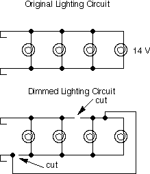 The cheap and dirty way to dim the
lights is to rewire the four bulbs from a straight parallel
configuration to a series-parallel configuration as shown in the
diagram. This puts half the voltage on the bulbs and makes them
burn about right. It will also extend the life of the bulbs to
approximately forever. It is also be possible to put a voltage
regulator on the bulbs set to 7.5 volts to produce the same effect
and provide more consistently bright lighting at low speed, see
below.
The cheap and dirty wiring is really easy, you just need to cut two wires and add one wire under the roof. The hard part is getting the roof off and back on. There are two screws under the roof at each end of the car which are accessed through holes in the floor. You need a very slender and long #1 or #2 Phillips screwdriver and some considerable patience to get them out. You need even more patience to get them back in, especially on cars without end doors like the RPO. A strongly magnetic screwdriver would probably make things easier, but I didn't have one that would fit so I drilled out the access holes until an available screwdriver would fit. Once the screws are out, the roof simply lifts off and the under roof wiring is completely accessible. Some versions of the heavyweights have clips at the center of the car which also hold the roof. If the roof doesn't lift off easily, gently pry one end up so that you can gently pry the wall of the car outward to clear the clip.
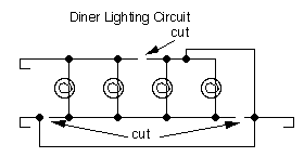 The diner has a little
bit different wiring. There is another power contact at the other
end of the car to route power to the LEDs that are used for the
eight table lamps. This connection needs to be replaced once you
cut the other wires. The LEDs do light up, but they are pretty dim
until the track voltage gets fairly high.
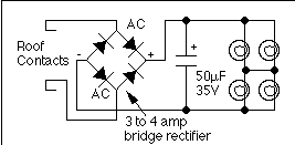 An incremental improvement on the cheap and
dirty lighting circuit is to add a bridge rectifier and a storage
capacitor with the lights wired in series-parallel. At slow speeds,
the capacitor can charge on the peaks of an Aristo PWC pulse and
supply more energy to the lights than the cheap and dirty method.
Note that the bridge rectifier is a big one, rated at 4 amps. Even
though the average lighting current is about 250 mA, at low speeds,
the capacitor tries to charge at a high rate, perhaps several amps
peak. Ordinary 1 amp diodes will survive the pulsed current, but
their voltage drop will increase to several volts and cancel the
advantage added by the capacitor. This circuit will only provide an
advantage if PWC is used, with pure DC power nothing is gained and
the extra diode drop will make it actually worse than the cheap and
dirty method.
 This is a somewhat fancier "constant intensity" version of the
lighting modifications. It uses an adjustable regulator to set the
lamp voltage to 7.5 volts which I have selected as the "right"
intensity. This intensity also matches the cheap and dirty version
above.
The advantage of this version of the circuit is that the lights come on to "full" intensity even at very low speeds IF you are using Aristo PWC. With a linear power pack, there is some improvement over the cheap and dirty version but is probably not worth the trouble. With PWC, there really is a significant difference. In this case, 1 amp diodes are adequate because the extra voltage drop in the diodes doesn't hurt as much. Still a 4 amp bridge would be even better allowing the lights to come on at a slightly lower speed.
To build this circuit you need these parts:
I assembled the circuit under the car roof. The heat sink was mounted to an available post at one end of the car with a small self tapping screw. The regulator IC mounts to the heat sink. During operation, this heat sink will get quite warm so its a good idea to put a fiber washer (or one made from cardboard) between the heat sink and the plastic post molded into the car roof. Depending on your track voltage, the dissipation of the regulator IC may go as high as 3 watts. If the regulator gets too hot, it'll shut itself down for self protection. The bigger risk is that the heat will melt the roof. Make sure that there is a gap between the heat sink and the roof.
Even if you don't change the intensity of the lights you should install a diffuser in the clestory windows. The lamps are directly visible through these windows and the bright spots are very distracting. Simply cut some strips of ordinary copier paper and tape them over the insides of the windows.
It is possible to get even better low speed lighting performance by using lower voltage bulbs. 5 volt grain-of-wheat bulbs run at about 4 volts should provide adequate lighting and they will reach peak intensity at even lower input voltage, even with linear power packs. However, beware of the regulator's dissipation. There will be more voltage drop across the regulator for the same total current and it will run hotter. If the bulbs draw more current, then the regulator will run hotter yet.
If you use DCC, the cheap and dirty method is the way to go. It works perfectly. The lights stay on all the time even if the train is not moving and the intensity is just right. There are no additional parts to add and this configuration draws the least current of any of the other methods.
[ Top ]The older production cars came with truss rods only on the diners. The manual states that the truss rods will not work with the other cars. The newer cars come with truss rods packed with all the cars, at least they came on all the cars that I got. With six wheel trucks, the rod and the truck almost interfere, and in fact, in some cases they do.
Steel cars didn't typically have truss rods. I installed them anyway and I didn't have any recognized trouble with the first three heavyweights. However, the fourth and fifth cars (a Combine and an RPO) developed derailment problems when being pushed on curves that weren't particularly sharp (something greater than 6' radius). I discovered that at this particular radius the corner of the truck was positioned right at the truss rod and sometimes the truck would hang up on the rod. A smaller radiuses, the truck slipped past the rod, maybe with a little bump, and didn't cause problems. The obvious solution was to remove the rods and the problem vanished.
[ Top ]When I got my cars, they didn't roll especially well. This is somewhat to be expected because of the weight and the extra wheel and bearing friction. I lubricated the wheel bearings with a light conductive oil and it helped. After awhile, the very light oil partially evaporated and the cars lost some rolling capability again. This time I lubricated the bearings with LGB 50019 Special Oil (my favorite stuff) and the rolling qualities materially improved and stayed that way. I've been using this LGB oil on all my wheel journals and over the test of time, it has worked very well indeed.
The trucks don't rotate particularly freely either without some treatment with graphite. Squirt some powered graphite around the curved slot on the bottom of each truck and work it in. Freedom of truck rotation is materially improved.