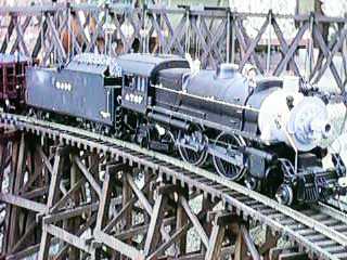
 I bought a Lionel Atlantic in
new condition from a collector for a good price. I liked its looks, but
I didn't like its performance. It made a lot of noise, was very
sensitive to dirty track and it wouldn't pull its own shadow. However,
I wasn't ready to give up on it because it was heavily built and looked
like it could be fixed.
The saga below describes what I did to it to convert it to a fine running engine. Except for some weathering, I'm done working it over and now it runs very well. It is one of my favorite engines.
The Lionel Atlantic is modeled after a Pennsylvania Railroad E6 Class Atlantic. The scale is close to 1:29 except that the drivers are too small and therefore the rims are too far apart. The E6 was developed before 1920 to haul passengers over the mostly flat parts of Pennsy's system and it did very well for many years. It could run very fast with 5 or 6 heavyweights so that it could keep tight schedules. You won't often find this kind of engine pulling freight. It's a high speed engine and just doesn't have the deep down grunt capability to start heavy loads.
 30 Aug 02
I also made other modifications that are not specifically described here
The Atlantic is powered by a single heavy duty motor which drives both drive axles through a brass worm on each motor shaft and a large plastic gear on the axle. The drive is simple and heavy duty but it had two problems.
The motor is mounted to the frame with a single small cable tie. The cable tie was not strong enough to hold the motor in place and it tended to squirm around. I found that when the motor canted off to one side, the gearing would complain by making a lot of noise. I fixed this problem by wrapping two heavier cable ties around the motor and cinched them tight. This was the end of the motor mount problem and also the end of most of the gear noise.
The axles ride in grooves in the plastic frame. There is quite a bit of slop in the axle position. This "feature" was probably intended to allow the axles to float a little to allow them to ride over uneven track. This rocking action by itself does not cause much of a problem, but under heavy load, the whole axle can move downward and the worm will skip over the teeth of the plastic gear. This is not only hard on the gears, but it allows the front and rear axles to get out of sync with each other causing the siderods to bind.
This looked serious so it had to be fixed. I glued 20 mil shims to the bottom cover directly beneath the axles to hold the axles to the top of the groove and push the drive gears right up against the motor worms. This eliminated the rocking axles which was a downside, but the gears no longer slop around and they stay meshed.
[ Top ]
The stock Atlantic picks up power from the drivers only. All the other wheels on the engine and tender are plastic. Four wheel power pickup wasn't going to cut it, so I changed out the leading truck and tender wheels to metal wheels and installed power pickups on the tender. I was not able to locate a suitable wheel set for the engine trailing truck so it remained plastic.
I initially used Gary Raymond finescale 33" wheels (133RS on the tender and 133FS on the leading truck). However, these wheels are have a narrow tread and a shallow flange and caused serious derailment problems. Where the track was a little wide, the wheels would drop between the rails. I then used Dean Lowe wheels (small ones on the front, about 0.9" diameter) and larger ones on the tender (1.08" diameter). These worked much better, but modifications to the engine and tender wheels are required to install the new wheels.
The pilot truck must be modified to install metal wheels. The old wheels can be pulled off the axle and the wheels removed. However new wheels can't go back on the same way unless you have the equipment to press the wheels off and back on the axle. Instead, I cut slots in the bottom of the truck to allow the axle to be snapped in from the bottom. The slot should be cut about 20 mils narrower that the axle diameter and the new axle will simply pop in or out as necessary. The bearing ends of the axle are no longer needed so that they can be cut off if desired.
There is not a lot of room on the truck body to mount power pickups, but LGB #63120 contacts could be installed by drilling a 13/64" hole through the truck body so that the contacts will bear against the wheel backs. After wires are soldered to the ends of the contacts, the contacts can held apart with a styrene shim inserted between the back ends of the contacts. I didn't actually install power pickup on the pilot truck wheels, I used the tender wheels instead. If you do install pickups on the pilot wheels, then you can avoid a jumper wire between the tender and the engine.
Another reader of this page suggested using Aristo Pacific leading truck wheels and bushings. He says that it works fine and you won't have to cut up the truck to install them. Also wheel drag would be less with the Aristo bushings instead of backside wheel contacts.
[ Top ]
The power pickups for the drivers are carbon brushes held against the wheel rims with light springs. These crapped out on me as the springs overheated and lost tension. Also, due to a short circuit one day, one of them melted into the plastic pocket and I had to grind out the contact and drag out the toasted spring. Since I was pretty sure I couldn't get replacement parts and the pocket was damaged anyway, I instead changed out all four contacts to LGB contacts.
To change out the contacts, drill out the rivets holding the brass brackets to the bottom cover and remove the brackets. Drill full through all the contact holes with a 13/64" drill and then reinstall the brackets with #4 hardware. If you use pilot truck contacts, drill a small hole on the front of the cover and route the wires from the pilot truck to solder to these brackets. If you have tender wheel contacts, drill another hole in the rear of the bottom cover and route a pair of wires to the rear. These will be used to connect to the tender.
Drop LGB contacts in the four holes so that they rest against the brass brackets and reinstall the bottom cover.
[ Top ]
The Dean Lowe wheels that I used needed modification before they would fit in the Lionel trucks. The axle ends were too long and needed to be shortened 1/8". Use a motor tool with a cutoff wheel to trim the axle ends and then use a grinding wheel to clean up the sharp edge created by the cut.
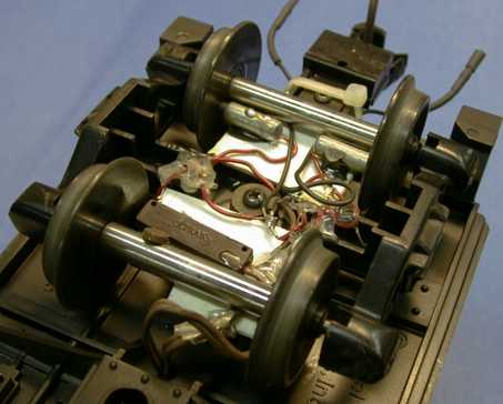 There isn't much surface
to mount contacts on the tender trucks. I cut four 1" squares of 1/16"
styrene and epoxied them to the trucks under the axles. I then epoxied
the contacts to the styrene. Solder wires to the ends of the contacts
before you epoxy them down so that the heat of soldering doesn't soften
the epoxy. Where there is room mount the contacts above the axle and
place the contact as close to the axle as you can get it. This reduces
the non-trivial drag that the contacts cause. Use very flexible wire to
attach the wires from the trucks to the inside of the tender. Drill
holes through the tender floor to route the wires. If you install a
sound system, you can later mount a chuff reed switch to one of the
pieces of styrene.
Wire the tender power pickups to the engine power pickups with a connector of your choice. I used a Molex two terminal polarized connector from the 062 series. My parts came packed as three complete pairs and labeled 1625-2PRT. Be sure that you get all the contacts on each side of the engine and tender wired together or else you'll have a short circuit.
After you've installed power pickup on 12 to 16 wheels, you have a hard time finding track the engine won't run on.
[ Top ]
The Atlantic has one of the best headlights in any large scale loco. There is no other illumination so I added illuminated markers and an illuminated cab.
I used Radio Shack 272-1092c Grain Of Wheat bulbs. These are 12 volts so I wired each pair in series. One pair is used in the front markers, one pair in the cab and a third pair in the tender markers.
To install marker lamps, remove the colored lenses with a sharp tool and then scrape some of the metallization off the back of each one so that light can get through. Then drill up through the bottom of the marker body with a drill just large enough to clear the bulb. Drill these holes by hand so that you don't overdo it. Insulate the leads of the lamps with pieces of insulation stripped from fine wire and then hold the new insulation in place with a piece of shrink tube over the insulation and the bottom part of the bulb.
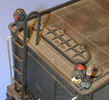 When you drill out the
inside of the tender markers, the mounting tab for the lamp will be
gone as well. I epoxied a short piece of 0.25" brass tubing to the
bottom of the marker such that the tubing fit over the mounting stub on
the tender shell.
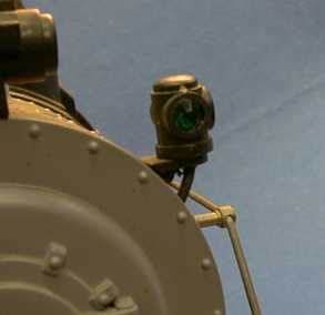 The engine markers are
wired through small slots cut in the front of the smokebox just below
the slot that mounts the markers. The engine smokebox cover just pulls
off and pushes back on.
The cab lights are simply hot glued to the cab roof and wired through the a hole drilled near the top of the firebox.
[ Top ]
The Atlantic is far too light to pull effectively, especially when you add the load of power pickups. I added over 3 pounds of lead fishing weights to frame inside of the boiler. There is a lot of room in there. Attach the weights to any surface available with your favorite adhesive. I used Crafter's GOOP, its strong and sets fast.
With enough weight, the Atlantic will hold its own against other large scale engines in pulling power. The motor and gearing are easily strong enough to handle the load.
[ Top ]
Sound is up to you. Some Atlantic's come with Lionel Railsounds. Mine didn't come with sound and even if it did, I couldn't have used it as the Railsounds is incompatible with Aristo PWC. PWC will burn up the Railsounds unit in a few seconds.
I installed a system from PH Hobbies. This is a pretty conventional digital sound system. I mounted the speaker in the center of the tender and drilled a bunch of 1/4" holes through the tender floor to let the sound out. I then mounted the sound board to the back of the speaker with a piece of foam mounting tape. The rechargeable battery mounted to the tender floor ahead of the speaker. It was so big that I had to mount it at an angle and it barely fit. The volume control was mounted in a 1/4" hole drilled through the tender floor.
I installed an Aristo ART-5474 in the tender to control the bell and whistle sounds of the sound board. I mounted it to the top of the tender body with hot glue. I then stuffed the inside of the tender with fiberglass packing to damp the sound a little.
The reed switch for the chuff was a little problematic. I first mounted 4 magnets on the back of a driver wheel and installed my own reed switch as the one supplied by PH was to big to fit there. I got a prototypical chuff, but the sound system really couldn't handle it at high speeds. I then mounted a single magnet on a tender axle and get 2.5 chuff/turn. This actually worked out better and I didn't need an extra pair of wires leading between the engine and tender.
[ Top ]
The stock drawbar is too long. The tender sits way behind the engine. This is necessary to allow the engine to work on 2' radius curves, but it looks bad. I found that I could simply drill a new hole for the mounting screw halfway along the drawbar and screw it back on with the original hardware to pull the tender right up next to the engine.
[ Top ]
The valve gear on the Atlantic has a tendency to fall apart. When the brackets that attach to the loco frame get a little loose, the valve rod tends to fall out and then the piston rod, backhead slider and connecting rod falls off too. Usually, the mess of parts hanging off the side of the engine will stall it. Before you pick the engine up, look on the track for a few feet back for the valve rod. This is a piece of wire about 3" long with short hooks bent in both ends. It won't be far away.
Use the still assembled side of the engine to see how the rod goes back in. You will probably have to loosen the brackets to get the rod installed again. Make sure that you tighten both brackets again.
[ Top ]
I recently purchased a Digitrax Chief DCC system and I chose to convert the Atlantic first. There were several reasons for picking this engine, but most of them impacted the complexity of the conversion. I just thought that the Atlantic would be the easiest to convert of any loco that I had. The Atlantic wiring is easy to get at, and there is gobs of room inside the boiler. It also had an older PH Hobbies digital sound system in the tender so that I could evaluate sound control as well. I selected the largest decoder, the DG580L, for use in this loco. This is a 5 amp decoder. The Atlantic could have gotten along just fine with the 3.5 amp version, but the larger decoder was only about $5 more and its not likely to have any trouble with this engine.
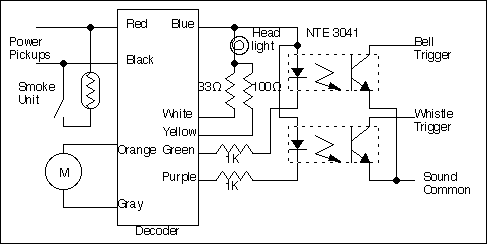 The first step in
any DCC conversion is to isolate the motor. This means that
BOTH motor leads must be brought to the decoder and
disconnected completely from the track. The motor terminals in the
Atlantic are accessible from the top once the boiler is removed, see
the disassembly instructions below. All that was necessary was to clip
the motor wires out of the wiring harness and hook them to the orange
and gray leads of the decoder. The red and black wires from the decoder
go back to the harness where the motor leads were clipped. The Atlantic
harness is really just two wire bundles. There are wires leading to the
track pickups, the headlight, the smoke system and the motor. These
wires are simply tied together under a wire nut. I had additional wires
leading to the front marker lights and the cab lights.
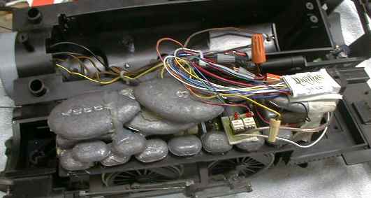 As you can see from
the photo, I've added a lot of lead to the Atlantic, something like 3
lbs because it needed it. I mounted the decoder on top of one of the
weights with a piece of foam mounting tape. The motor wired to the
decoder with more wire nuts. Headlights are wired to the F0 forward and
reverse outputs through resistors to cause the brightness to be reduced
running in reverse.
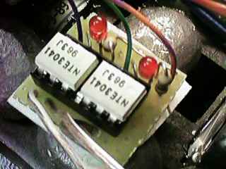 The sound system cannot be directly connected to the F1 and F2 outputs
of the decoder due to isolation requirements. I could have use reed
relays to activate the sound system, but I chose to use optoisolators
instead. These are mounted on a small piece of vector board that is
also attached to a weight with a piece of foam tape. I wired the three
sound control leads back to the tender with a 5 pin Molex type
connector. The other two pins bring track power forward from the power
pickups in the tender.
The photo shows two red LEDs that aren't on the schematic. I added these in series with the LED's in the NTE3041's for diagnostic purposes. They are so cheap, that it wasn't worth the trouble to remove them after the installation was done.
The PH Hobbies sound system needed little attention. I did have a problem with DCC buzzing getting into the sound. This was because the batteries had gotten a little dirty and their AC impedance was not low enough to properly filter the noise. After cleaning the batteries and the holder, most of the noise was gone. Also, with the higher average track voltage, the regulator IC got really hot. I added about 40 ohm 1 watt resistor in series with the power input to the sound board to drop 6 volts or so and the regulator ran much cooler.
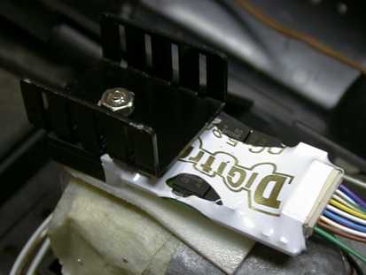 This
Digitrax DG580L decoder had been in the Atlantic for over two years
before I decided to replace it. The loco always did tend to lug down
and stall under heavy load. This is because the Digitrax decoder
couldn't source enough current to the motor and it would just lug down.
It could sit there with its drivers stalled, buzz like mad and not go
anywhere. Even with all the extra weight, this engine should be able to
slip its drivers, but the motor couldn't develop enough torque to do it
on the limited current that the Digitrax decoder provided. The decoder
has obviously been hot, even with the heat sink added to the rectifier
housing, the shrink wrap around the switches has melted and pulled
back.
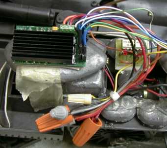 I purchased a
Zimo MX65S/N to go in another loco, but before I put it there, I tried
it in the Atlantic. With the Zimo decoder, the engine will slip its
drivers and it doesn't make that awful buzz that the Digitrax decoder
made. I've used three of these decoders now and each has worked
perfectly.
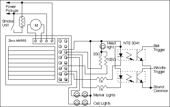 The
schematic of the Zimo installation is pretty straightforward. All the
loads are either connected to the decoder or switched (smoke) so that
they are disabled during decoder programming. Even though it is
probably possible to trigger the sound system from the function outputs
of the decoder directly, I use optoisolators just to be safe. Besides,
they were already there left over from the last Digitrax
installation.
[ Top ]
The Lionel Atlantic is easy to disassemble and reassemble
[ Top ]
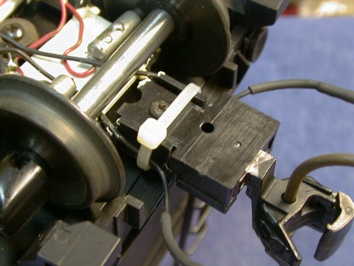 A Kadee 831
coupler will fit on the tender truck of the Atlantic, however it takes
some grinding on the coupler mount to make it fit. Specifically, the
side panels on the mount need to be severely ground down.
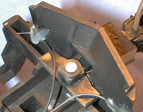 The
front coupler is a special. I don't remember which one I used. Kadee's
web site lists a 794 as being for the Atlantic, however, the drawing on
the web site shows only a version looking like an 831. The coupler box
body has a tab extension, a special spring and a coupler of special
mounting parts.
With the box mounted this way, it is not very visually attractive, but it works. The coupler swing is limited so don't plan on using this coupler on less than 8 foot diameter track.
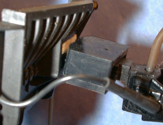 However, the vertical position of the
coupler was not well controlled by this mount. I added some styrene
shims in the pilot pocket to prevent the box from drooping.
© 1997-2002 George Schreyer
Created Oct 5, 1997
Last Updated August 30, 2002