I've been reading a bit lately about a new transmission for automobiles. If you are an auto buff, you'll recall the manual transmissions since nearly the beginning of time - three forward gears and one reverse. You might also understand the transmission in the Model T Ford. It used a planetary gear system which is used in most automatic transmissions of today And, now, comes the "continuously variable" transmission, meaning it doesn't go in steps, like first, second and high, but smoothly moves along on an arc. Do you follow me?
I don't know why it took the auto industry so long to come up with a continuously variable transmission. We had one in our "speeder" in the logging camp, a commercial vehicle built, I would guess, in the 1920s. On railroads, a speeder is a small track vehicle usually used for carrying workers. When I was working summers on the bridge crew in the late 30s, and when we were not building a new bridge, we would examine and make minor repairs to bridges on the main line to Pino Grande, the sawmill. It was then that the speeder was assigned to us. There is another story posted here about building bridges. This story is about that speeder, for it was unique.
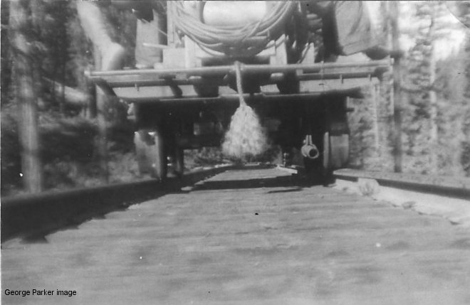
I have searched the web looking for photos or descriptions of a speeder like ours, but to no avail. Most of them are, at least, partially enclosed, and have comfortable seats. Ours was more like a flying carpet. I have but one photo taken when, in jest, we tied a frayed rope to the back of the machine to represent a tail. Unfortunately, it only shows the lower portion of the vehicle and gives little impression of the complete vehicle, so I'll try to describe it, and the harrowing rides we had on it.
The vehicle was approximately six feet long and four feet wide with a flat wooden top and foot rests on each side. Picture a small picnic table. One sat on the table with feet resting on the bench, so that when travelling, one moved sideways. The only projection I remember was the gear lever that slid in a slot atop the speeder, which I will describe later.
It's a pity I don't have a photo of the whole machine, but, as I recall, there was an arrangement on the right side of the vehicle for the driver, who could face forward and have certain controls available, such as the starter button, clutch lever, brake pedal and gas lever. There was room for three passengers on the left, and two, besides the driver on the right.
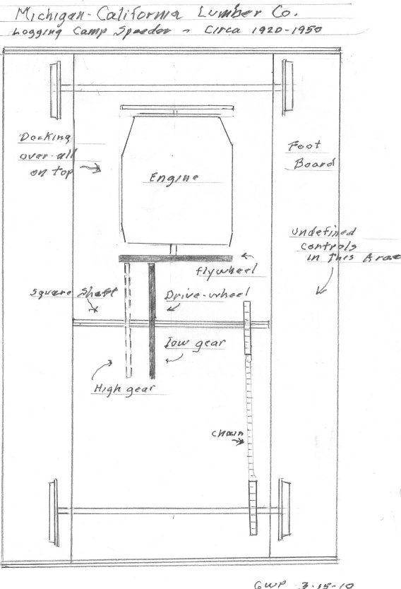
The engine was a four cylinder Continental gasoline engine commonly used in passenger cars of the day, located under the deck in the front. Instead of the conventional enclosed flywheel followed by a transmission case, there was a large flywheel, perhaps fifteen inches in diameter and two inches thick, attached to the crank shaft, and completely exposed. At a right angle to this flywheel, was a similar metal wheel, and with similar dimensions, which I will call the drive- wheel, mounted on a square shaft so that it could be slid to the right and left of the flywheel. When this square shaft was moved forward by means of a lever, the drive-wheel came in contact with the flywheel, causing it to rotate, as the flywheel rotated. This drive-wheel shaft, by means of a chain and toothed gears, turned the rear axle. Because the drive- wheel could be positioned at many different positions on the flywheel, different gear ratios were obtained.
If the drive- wheel is placed three inches from the center of the flywheel, the circumference of the flywheel at that point is about eighteen inches (2 x 3 x 3.1416, or 2 x r x pi). The circumference of the drive wheel is always about forty-seven inches (7.5 x 2 x3.1416). The result is that the engine must rotate about three times for the drive wheel to rotate once. Let's assume that the axle wheels will also rotate once. In an automobile this would be similar to driving in low, or first, gear.
Now, if we place the drive wheel at the outer edge of the flywheel, say seven and one-half inches from center, the circumference of the flywheel and of the drive wheel will both be about forty-seven inches (7.5 x 2 x 3.1416). Thus for every turn of the engine, the wheels make one turn, similar to high, or third gear, in an automobile. So you see, we had a continuous variable transmission. And, place the drive-wheel to the opposite side of the flywheel, and the speeder will go in reverse.
So, get aboard! We're about to take off. The driver puts the drive wheel close to the center of the flywheel and we start out. As we gain speed, he slides the drive wheel to the outer area of the flywheel, and by adding more gas, we really move. You're sitting sideways on the deck, gripping the wooden top, and your feet on the narrow footrest.
Bill, the bridge boss, is driving and it amuses him to scare us. There was no speedometer, but I would say that at twenty-five miles-per-hour, the car could jump the track on that curved, narrow-gauge railroad. Forget twenty-five, fifteen was exciting enough, but we never had an accident.
At each end of the speeder was a horizontal bar for lifting. Two men could back up to the machine and lift one end, sidle with it ninety degrees, and then pull it off the track, and It was powerful enough to pull a small flat car, on which tools could be placed. It was an ideal vehicle for small crews, and for quick and emergency transportation.
Where is this vehicle I knew over seventy years ago? If any reader has knowledge, memory, or a photo of this speeder or one similar, I would be indebted if you if you contacted me at geowparker@astound.net. We'll reminisce together.
George W. Parker Burlingame, CA 3-17-10