MILITARY RAILROADS
OF THE NEW YORK METROPOLITAN
AREA:
FORT TILDEN
Rockaway, Queens
.
.
.. |
|||
update summary |
date |
||
| Battery Harris plan / blueprint added | 14 May 2019 | Casemate Construction Information | |

. Ft. Tilden was created in 1917
as the site of a Coastal Defense battery. In later years, it would transform
into a Nike Missile site. Ft. Tilden was a short drive from my former residence
in Brooklyn; and my friends and I would spend time there exploring during
beach parties. I remember many standard gauge tracks running in and around
the concrete fortifications and under sand dunes.
Many remnants of the "Fort Tilden Railroad" can still be located: they show through the macadam on the roads, as well as a few railroad ties. But the best are the tracks running through the fortifications facing the ocean. By the way, this railroad was not connected in any way to the LIRR Rockaway Branch (later absorbed by the NYC subway).
.
| Before we progress any further,
it bears mentioning that this websites intent is to primarily focus upon the
railroad aspect and history of the location. This will undoubtedly have the unfortunate side
effect of not discussing a significant amount of historical detail
pertaining to the overall location; so I strongly urge those
interested readers to visit the: .
That website covers the coastal defense locations throughout the
United States with a detailed history, along with hundreds of plans, blueprints,
specifications for both general construction and armaments at those locations,
|
.
.
.
Fort Tilden is a former United States Army installation, and served as a coastal defense site, and protected the entrance to New York Harbor in conjunction with Fort Hancock, NJ. In 1917, Congress approved the installation of two 16" - 50 caliber (50 x 16" bore = 66.6 feet length) rifles to be installed at Fort Tilden, NY.
To put things in perspective, these rifles are very similar is design to the rifles mounted onboard the Iowa Class battleships. (BB61 "Iowa", BB62 "New Jersey", BB63 "Missouri" and BB64 "Wisconsin".) Fort Tilden guns were mounted singly (one gun - one casemate) whereas the battleships are mounted three guns to a turret.
If one were so inclined to invade Upper New York Harbor, (as an invading naval force) and likewise Manhattan; and if by some miracle, one managed to elude or survive a barrage of "interlocking" fire from Forts Tilden and Hancock, you would still have to contend with Forts Hamilton (in Brooklyn) and Wadsworth (in Staten Island). These two forts were located farther north in Lower New York Bay.
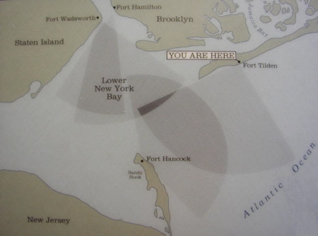
US DOI NPS graphic
.
Upon the conclusion of World War II, and the advent of new rocket weaponry; the concept of defending harbors with heavy artillery was obsolete. World War II changed twenty years of military strategy, and with it, Fort Tilden evolved from coastal defense battery to anti-aircraft emplacement, known colloquially as "Triple A" batteries.
Then again in 1954, military weaponry evolved once again, and the Army replaced the anti-aircraft artillery with "Nike" ground-to-air defense missiles. Nike Missiles were designed to intercept and destroy fast moving jet aircraft at high altitude, before they reached the metropolitan area.
Nike "Hercules" air defense missiles were equipped with both conventional or small yield (20 kiloton) nuclear (fission type) warheads to increase effective destruction area and to increase the probability of disabling a majority of a aircraft squadron, as opposed to a single aircraft.
The introduction of Inter-Continental Ballistic Missiles (ICBM's) totally invalidated Nike air defense system and in 1972, Fort Hancock was decommissioned and transferred to the National Park Service, where it is now administered to as part of the Gateway National Recreation Area.
.
.
Casemate Construction Information
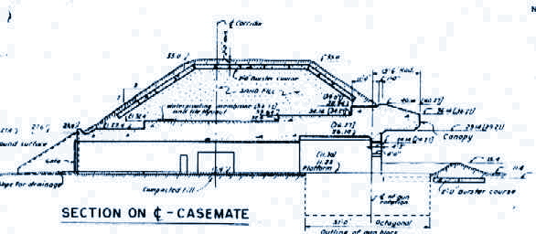
History of Ft. Tilden website image
.
The coastal batteries at Fort Tilden were topped with 6 feet of steel reinforced concrete, on top of 2 foot thick steel "I" beams and had mounds of earth pushed on top that. The batteries were approximately 200 feet long, 50 feet high, with the track running through the center of the long axis of the battery. Halfway through the battery, is a lateral corridor. There are two purposes for this, the first gives ready access to the breach of the gun. The second, should the breach of the gun ever fail while being fired, the explosion would be vented directly out the back of the casement, instead of being bottled up inside the casement; naturally with catastrophic results.
On either side of the lateral corridor, are two rooms approximately 20 x 20 feet each (two on each side of the artillery piece) alongside the track, with thick steel doors. These rooms were for the storage of gunpowder bags, and projectiles. In between these two room is an open alcove, with a light fixture and what appears to be wiring conduits. I believe these were command centers.
Also there was a sizable lavatory, and small 10 x 20 room (for plotting? rest area?)
.
.
The following maps were located on the web by Joe Roborecky within the website of the Coast Defense Study Group. The last revision date on all maps below is November 28, 1921. I have left these maps large so as not to lose detail.
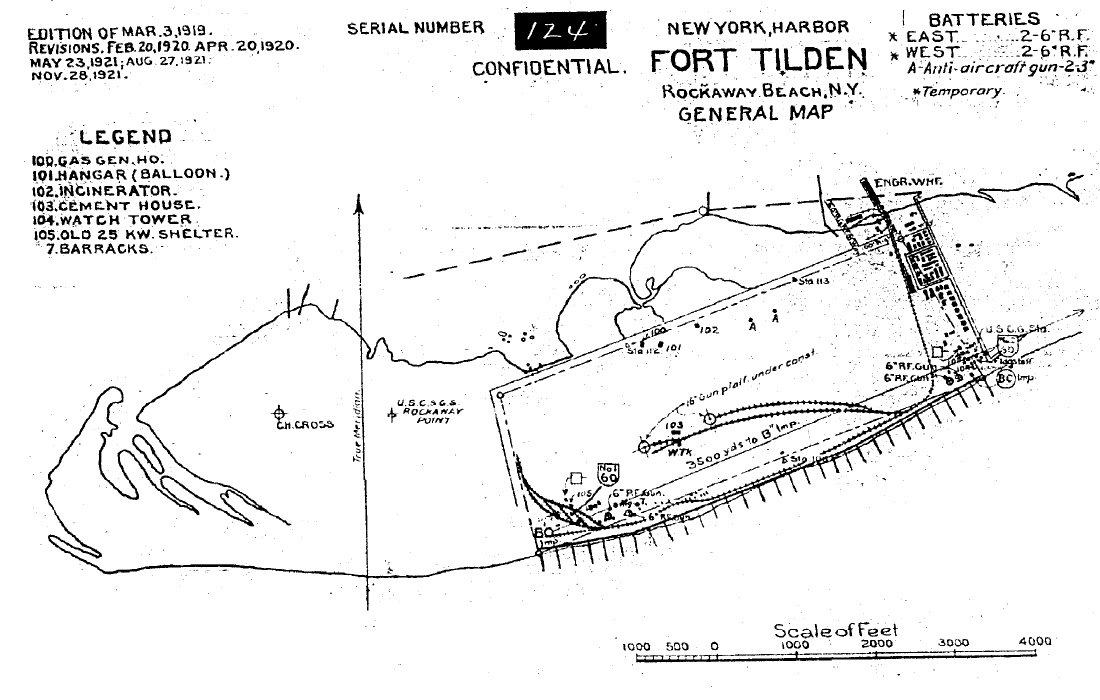
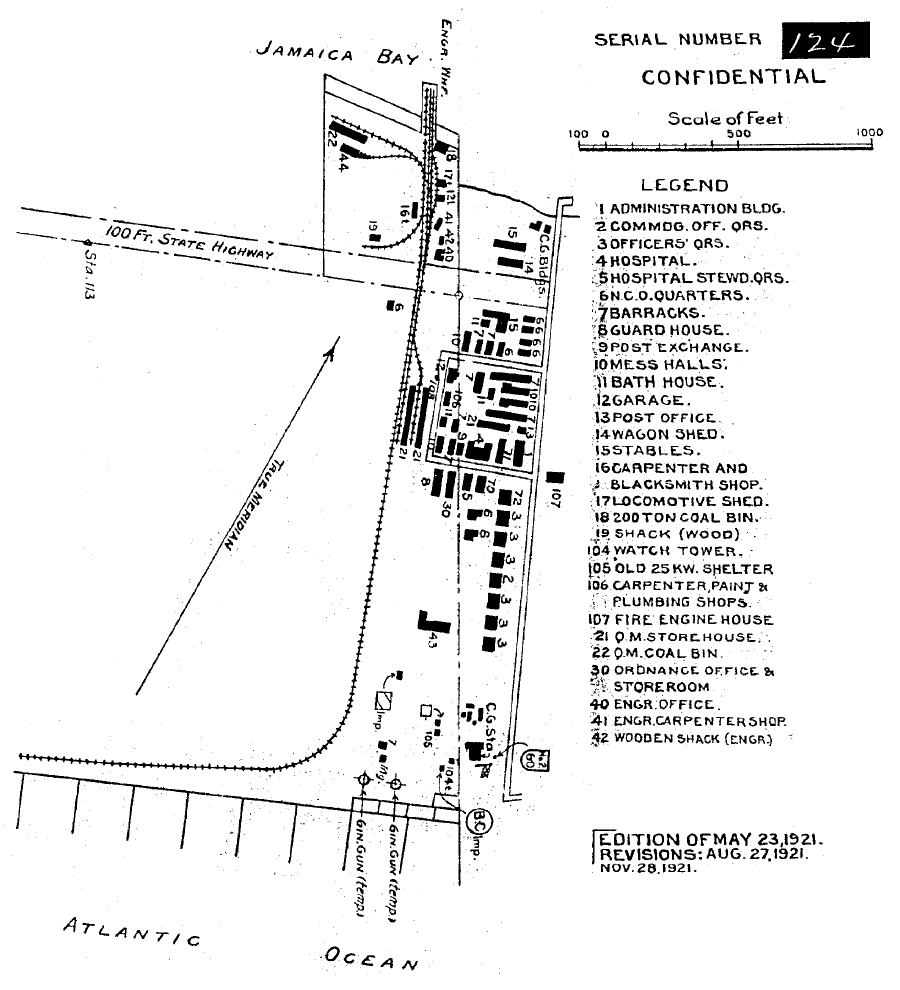
maps from the website of the
Coastal Defense Study Group
originals reside in the National Archives.
The legend for symbols used on the above map be viewed here: 1920 Series Confidential Maps Symbols & Abbreviations.
added 10 January 2011
.
.
. |
1920 - 1923
The railroad was first constructed to move railway mortars to and from their firing positions. Railway mortars in the United States first saw use during the Civil War, and were improved upon based on their mobility. Later, the Fort Tilden Railroad would be re-constructed to supply the fixed base guns of Fort Tilden with ammunition which was delivered by ship to the fort's wharf, which was located adjacent to the current US Coast Guard installation in Jamaica Bay. The railroad tracks originally ran along the current site of Shore Road, along the beach.
Around 1920, four large 12 inch railway mortars were located at Fort Tilden for a short duration. As this time, the Fort Tilden RR would extend the trackage to the west end of the post and four double-ended sidings were built for storage of the railway mortars.
The track layout at this time is unknown.
|
|
.
.
Existing Fort Tilden trackage raises a very interesting issue: most of the locomotives recorded having been sent to Fort Tilden are shown as narrow gauge. But the trackage currently seen in place through the casemates is clearly standard gauge!
It is obvious the military replaced the narrow gauge trackage with standard gauge, but no documentation located to date reveals when this took place.
Fort Hancock by comparison (as seen in the 1918 map on that page); operated both standard gauge trackage for passenger, troop train and railway gun movements which allowed for interchange with Class 1 railroads (Central Railroad of New Jersey), but used a narrow gauge railnet for supplying the smaller artillery batteries with ammunition, projectiles, etc.
As Fort Tilden was not connected to any other railroad, it is not understood why the changeover to standard gauge was made. The low clearances in the casemate corridors obviously prevented standard height freight cars from entering and exiting the casemates.
As most (if not all) of the well recognized industrial locomotive firms, (i.e.: Vulcan, Porter / Davenport and Whitcomb / Baldwin and Plymouth; as well as some lesser known manufacturers (Atlas, Brookville etc), would continue to manufacture narrow gauge equipment. Even to this day narrow gauge equipment is available for mining and excavation, so obsolescence of a narrow gauge railroad would not be a factor.
So the reason for Fort Tilden's conversion to standard gauge eludes us.
1917 - 1923
The Fort Tilden Railroad was a rather small affair, comprised of just over a mile of track, with the majority of the right of way in a straight line except for the 90 degree curve coming off the wharf located in Jamaica Bay and some very minor curves going through the batteries.
Around 1923, the right of way would be rerouted to facilitate the construction and installation of the "modern" 16 inch guns of Battery Harris East and Battery Harris West, as well as the smaller guns of Battery Kessler and Battery Fergusson. No documentation exists, but it was most likely at this time, the railway was converted to standard gauge.
After the 12" railway mortars were replaced; the railroad's sole purpose was to bring artillery shells/projectiles from the shell magazines, as well as powder bags from those magazines; to the coastal defense batteries or fortifications, also known as "casemates". Then, these projectiles would be loaded and fired at approaching enemy vessels.
.
1923 to 1941
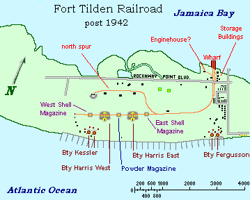
These tracks ran from the wharf area in Jamaica Bay, headed southeast about 500 feet, and began to turn west. At this point there was a turnout for the northern spur, which would take you to the 6" gun emplacements overlooking Jamaica Bay. Continuing straight however, the railroad extended through to three magazines and two gun positions of Battery Harris. Since the projectiles weighed 2,400 pounds each, this rail system was vital in providing an rapid system of supply of powder bags and projectiles to the guns to defend the coast from enemy invasion.
A locomotive would couple to one or two 4 wheel railcars about 6 feet long, (basically a very heavy duty rack on wheels) as well as a flat car; and would go to a shell house to pick up a quantity of shells. The shell magazine was not located very near the batteries, in case of accidental detonation by incoming enemy action or by sabotage.
The "train" would then transverse the trackage, where it would stop, and the shell carrier diverted to a circular track surrounding the gun. This way, no matter which way the gun may be aimed, a projectile carrier could be placed directly behind the breech. Artillerymen would, with the aid of a hoist pick up the projectile; and place it on the loading rack for the artillery piece and "ram" or shove it in inside the barrel. Then bags of gunpowder would be placed behind the shell, and the breach of the artillery piece closed. At such time, the artillery would be fired at enemy vessels approaching the coast. As we all know, no foreign naval armada ever was to attempt this, and the Battery Harris artillery pieces were never fired in anger.
If one references the two photographs below, surrounding each gun carriage is a set of tracks completely encircling the the gun for loading and maintenance. Of particular note in the left photo; is the track "wye" structure (which can be seen at left center) for turning railcars.
In the right photo, a projectile carrier railcar can be seen in right foreground, with a nice close up of the concrete embedded trackage resembling streetcar tracks. By using the gentleman's foot as a gauge, it is clear the trackage is standard gauge at the time the images were taken.
In the bottom photo, a projectile carrier railcar can be seen on the left as well as the circular track.
|
|
| . | |
|
|
.
1941 - 1954
Around 1940-1941, with propeller driven bombers of intercontinental capability starting to come off the production line; the concrete casemates were built to protect the guns from aerial bombardment. The circular tracks could no longer supply the gun, as the front vertical casemate wall was in the way. So, the casemate was designed so that the supply train would enter the casemate and unload behind the breech of the gun, in relative protection. A chain fall attached to the ceiling in the casemates assisted with the loading of the projectiles.
As one can see in the current aerial photo below, these circular tracks (seen in the above photos) are no longer in place, and a circular apron of poured concrete slabs is in place in front of the gun. This prevents muzzle blast from "kicking up" sand and dust.
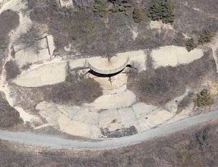
aerial view, 2006 - Battery Harris West
MS local.live.com photo
.
Battery Harris East and West each have four 20 by 20 foot rooms with heavy steel doors for the "in house" storage of powder and projectiles. When it was time for resupply, the resupply procedure was a "run through" affair. The railroad could access the fortification / casemate, from either the east or west shell house located at opposite ends of the Fort, and either side of the powder magazine which was located between the Battery Harris East and Battery Harris West.
.
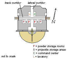
simplified top view of casemate
.
The "train" would then transverse the trackage, enter the battery through a portal in the side of casemates and proceed inside stopping directly behind the artillery piece at the lateral corridor. Artillerymen would, with the aid of a hoist or chain fall would pick up the projectile; and place it on the loading rack for the artillery piece and "ram" or shove it in inside the barrel. Then bags of gunpowder would be placed behind the shell, and the breach of the artillery piece closed. At such time, the artillery would be fired at enemy vessels approaching the coast. As we all know, no foreign naval armada ever was to attempt this, and the Battery Harris artillery pieces were never fired in anger.
For example: the railroad would begin its westward journey at the east projectile magazine, and into the east end of the building where projectiles would be loaded onto the railcar. The train would proceed through and out the westside of the building, and approximately 500 feet into the east portal of Battery Harris East. Proceeding out the west portal of the Battery and about 500 feet further west it would enter into the east end of the powder magazine where it would pick up powder bags. It would then progress out the west end of the central powder magazine "Magazine #2" (which was located between both Battery Harris East and Battery Harris West), and again travel about 500 feet into the east portal of Battery Harris West, where it would unload the powder and the projectiles.
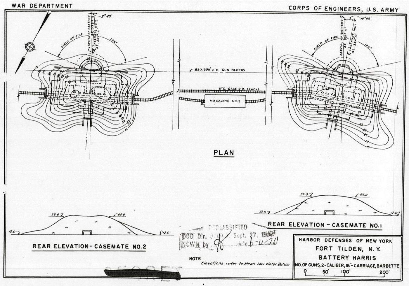
image courtesy of National Archives
added 15 May 2019
.
.
After unloading, the train would continue out the west portal of Battery Harris West, about 500 feet to the west projectile magazine, where the projectile carrier railcar would be loaded. The train now reverses direction heading eastbound, passing through Battery Harris West, to the central powder magazine, where it picks up powder bags. It continues it's eastbound journey into the west portal of Battery Harris East, and unloads both projectile and powder bag. Both Batteries are now supplied and are in process of firing at incoming ships.
Three smaller batteries would also receive supplies via the northern spur of the railroad, but train would not actually go into those fortifications as with the Battery Harris', and supplies would be dropped off trackside. These were much smaller casemates, at about 30 feet by 30 feet, housing 6 inch or smaller guns. If one references the track map at the top of this page, these three casemates are reflected by the three squares on the northern spur.
.
Remnants of Fort Tilden Railroad
In May of 2007; Paul Strubeck, my former stepson Joe and myself went to Fort Tilden, where we explored the old right of way of the railroad.
The only remnants of these "Fort Railways" remains at Fort Tilden (considering that the Brooklyn Navy Yard was a shipyard, not a artillery location). Fortunately, Fort Tilden is situated in the Gateway National Recreation Area, and is open to the public. Fort Tilden is where you can actually follow a pair of tracks from a sand dune into the fortifications.
If you intend to visit Ft. Tilden to see
the remains of the railway (or for any other reasons), I strongly suggest
the following:
.
|
|
| .
. |
|
|
|
.
. |
|
|
|
| .
. |
|
|
|
.
. |
|
|
|
| .
. |
|
|
|
.
. |
|
|
|
| .
. |
|
|
|
.
. |
|
|
|
.
. |
|
|
|
Battery Harris West
Shell Magazine
|
|
| .
. |
|
|
|
.
.
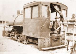
ALCo 0-4-0T
.
.
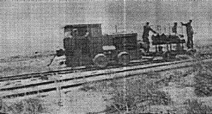
(Jay Reed believes this to be a Plymouth model DL)
.
.
Fort Tilden Locomotive Roster
builder |
c/n |
build date |
gauge |
wheel arrangement |
model | wheel dia |
cylinders |
acquired |
number / name |
disposition |
notes |
ref |
| H. K. Porter | 1887 | 8/1898 | 36" | 0-4-0T | 9" x 14" | new | [3] | |||||
| ALCo ? | 0-4-0T | sold 1929 | * | |||||||||
| Plymouth | B | DL(?) | 1929 | 8 Ton gas/electric |
* | |||||||
| truck | 1922 | * | ||||||||||
| speeder | B | * |
.
authors' notes:
Until it can be disproved, I am concluding there were two separate steam
locomotives to operate at Fort Tilden.
The H. K. Porter records are clear enough, but after searching the ALCo builders
records, I cannot locate any data thus far for an ALCo being sent to Fort
Tilden,
or any ALCo being purchased by the US Army that meets the specifications
as reported by Kevin Hanley.
If anyone can provide further information; please email me at:
bedt14@aol.com or
call: (845) 586-4672
* = please visit Ft Tilden webpage for loco information
.
.
For more information on the Fort Tilden installation, the specifications, guns and other equipment used, please visit the following websites
I highly recommend the first site on the list to anyone looking for the a comprehensive history of Fort Tilden:
| Coastal Defense Study Group website |
| History of Fort Tilden Website |
| Forgotten NY - Fort Tilden |
| Fort Tilden - Wikipedia Free Online Encyclopedia |
| NIKE Missile History and Sites |
Jay Reed
for assitance in identifying the Plymouth locomotive
Paul Strubeck
my assistant and co-researcher, for proofreading, editing and technical advice
Joseph Tanksley
my son, for sharing my hobbies, carrying my camera equipment and
10 million candlepower searchlight
Index:
Military
Railroads of the New York Metropolitan AreA | ||||
| EARLE N.A.D. N.W.S. EARLE | ||||
| FORT TOTTEN | Fort Terry | Fort Hancock / SANDY HOOK PROVING GROUNDS | ||
| . SIGN THE GUESTBOOK | ||||
.