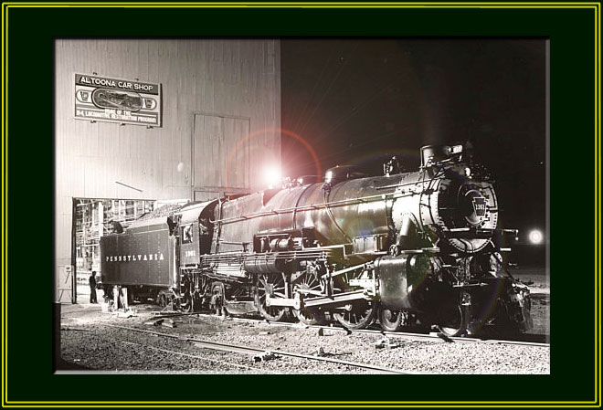
The PRR K-4s #1361
Steam Locomotive Restoration Project
Page 18
(This site is provided as a courtesy of the Altoona Railway Museum Club)
January 2005 K4 Update
These photographs were taken between July 2004 to January 2005 by Charles Cantrell, 1361 Volunteer.
.jpg) |
Stocker drive shafts return for McAdoo machine Company | .jpg) |
Close-up of shafts showing detail of the work performed |
.jpg) |
Another view of Stocker drive shafts comparing old to new. | .jpg) |
Close-up of gear teeth. |
.jpg) |
The stocker auger is mounted in Fixture to facilitate welding. The welding buildup process was necessary due to extreme wear of the auger flutes. | .jpg) |
Close-up showing the work in progress during the build up process. After Build up, the auger will be machined to the proper specifications. |
.jpg) |
After cutting, to proper size, bar stock is placed in the milling machine to begin millwork. The piece shown is the beginning of a new bonnet for the injector assembly. The original part was missing from the injector. | .jpg) |
Close-up of bonnets milling process 1. |
.jpg) |
Close-up of bonnets milling process 3. | .jpg) |
Close-up of bonnets milling process 3 |
.jpg) |
New bonnet mounted on injector assembly after completion. | .jpg) |
Rivets are removed to remove the tender floor. If you review earlier web updates, you will note that the tender floor must be replaced due to numerous large cracks and extensive wear. |
.jpg) |
Volunteer Charles Cantrell is shown removing rivets with an acetylene touch. Care must be used not to cut the tender side sheet. | .jpg) |
The rearmost tender floor section is removed after completing the rivet removal. The floor was removed in three sections to maintain alignment of the tender side sheets |
.jpg) |
Interior view of tender showing rear floor section removed. | .jpg) |
Another view of tender interior showing floor removed. |
.jpg) |
Volunteer Charles Cantrell maneuvers new tender floor section into place while volunteer Walter Elvidge maneuvers the crane. | .jpg) |
Volunteer Walter Elvidge manipulates rear floor section into place using a fork lift. At this point, the crane can no longer be used. |
.jpg) |
The next section of flooring is readied to be moved into position. | .jpg) |
. Interior view of tender showing the first two floor sections temporarily mounted into position. The sections are held in place using nuts and bolts until they are finally riveted into place. |
.jpg) |
Exterior view of tender showing new lower side sheets and tender floor. | .jpg) |
Interior view of tender showing the complete floor installed. Seems Will be welded prior to riveting. |
.jpg) |
Front view of tender showing new stocker side sheets and new left side slope sheet being fitted. The old right side slope sheet has yet to be removed. | .jpg) |
Front view of tender showing continued fitting of new stocker side sheets and new left and right slope sheets. At this point, the old cistern front sheets have been removed and the new sheets fabricated, drilled and replaced as well. |
.jpg) |
Another view of tender sheets being fitted. | .jpg) |
Interior view showing stocker side sheets and slope sheets being fitted. |
.jpg) |
Close-up of rear tender hold down plate after removal of old rivets. | .jpg) |
The scrap pile keeps growing. View of old tender floor sections after removal. |
.jpg) |
Section of tender floor nearest the front of the tender showing the extreme wear and rust. | .jpg) |
Tender brake lever being milled after build up work in the weld shop. |
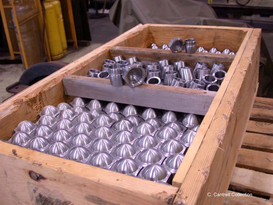 |
New stay bolt caps and sleeves arrive from Northwestern Stay Bolt Co. | 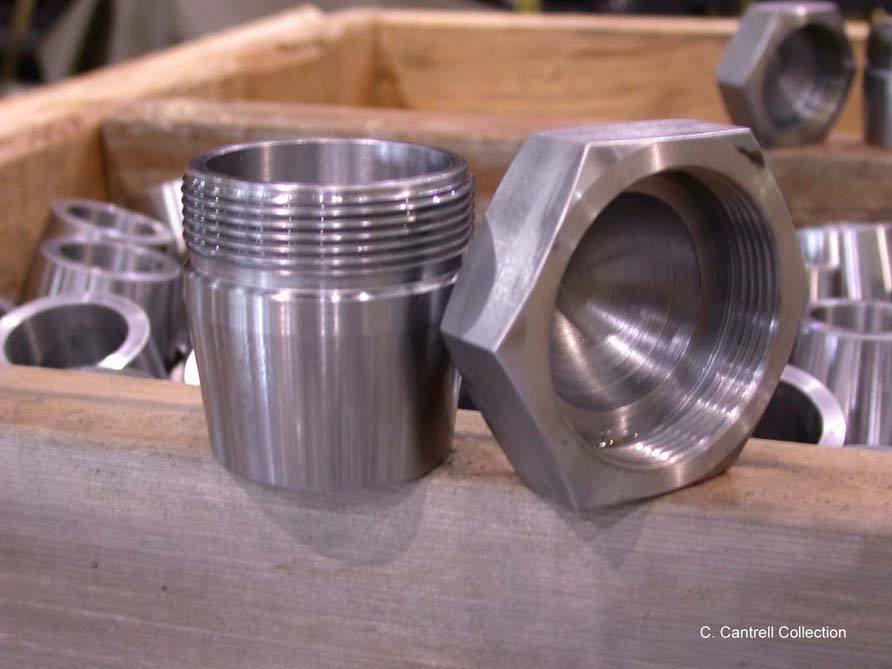 |
Close-up of cap and sleeve showing the quality of workmanship. |
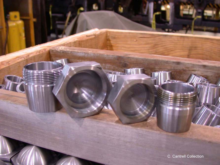 |
Another view of caps and sleeves. | 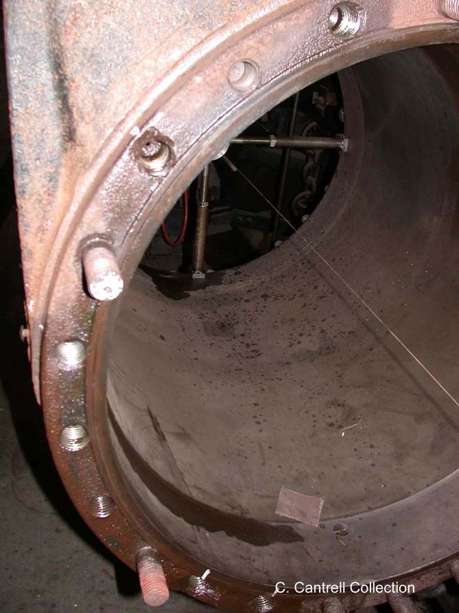 |
Close-up of front cylinder showing worn out cylinder cover studs. |
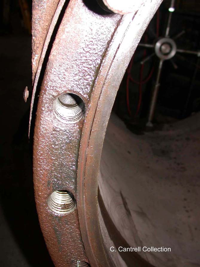 |
Close-up showing re-threading work on front cylinders. The front cylinders required re-threading to accept new cylinders cover studs due to the worn condition of the bolts and the wear on the cylinder threads. | 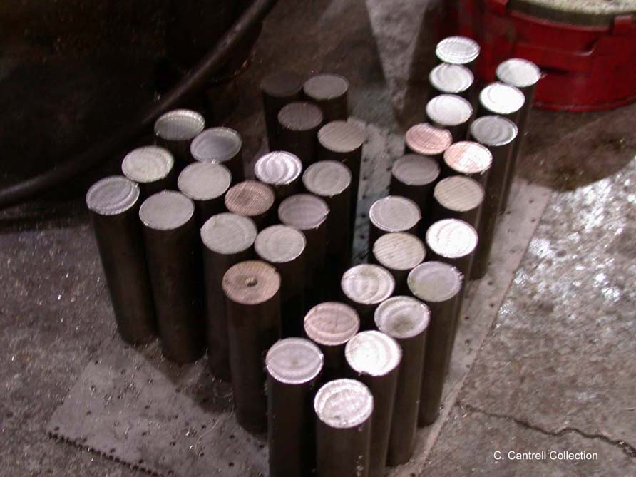 |
Bar stock is first cut to begin the manufacture of new cylinder head studs. |
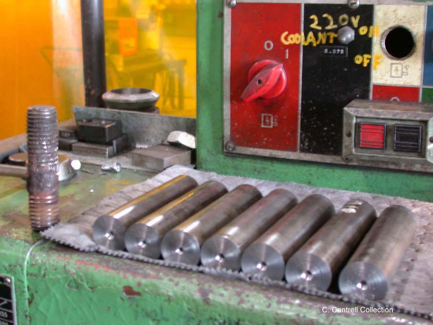 |
The bar stock is then faced and center drilled. | 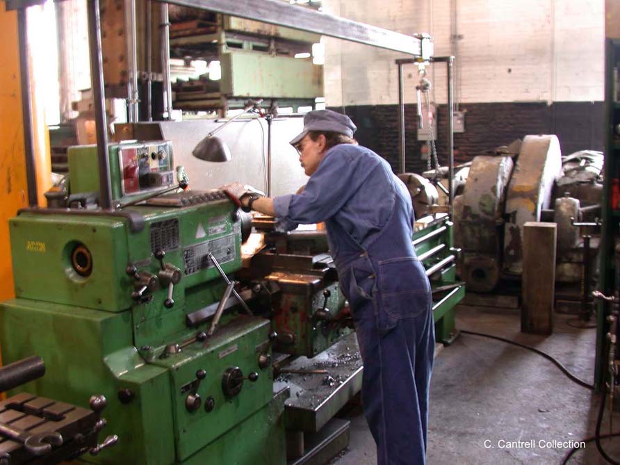 |
Volunteer Charles Cantrell at the lathe facing and center drilling new studs. |
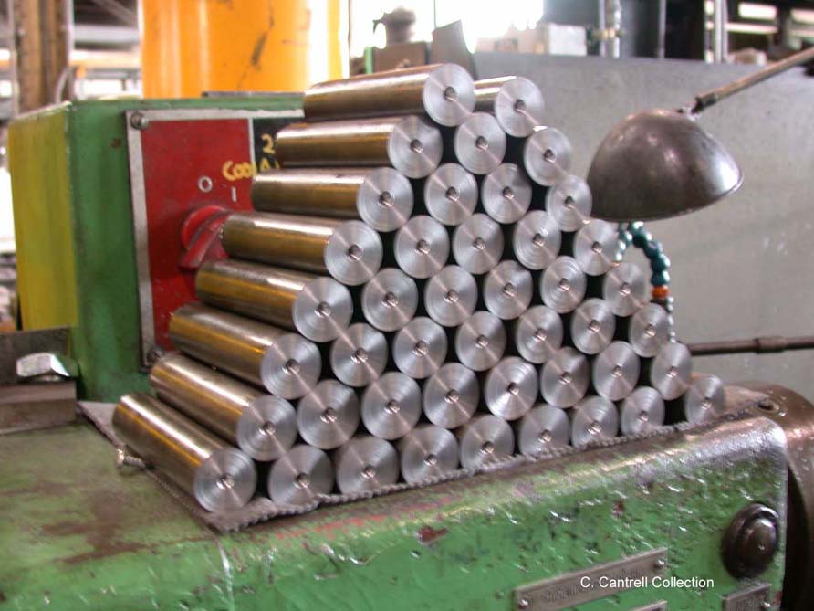 |
Close-up of finished work. Next the studs will be threaded to the proper thread size. Each stud will then be hand fitted to the cylinder and marked. | 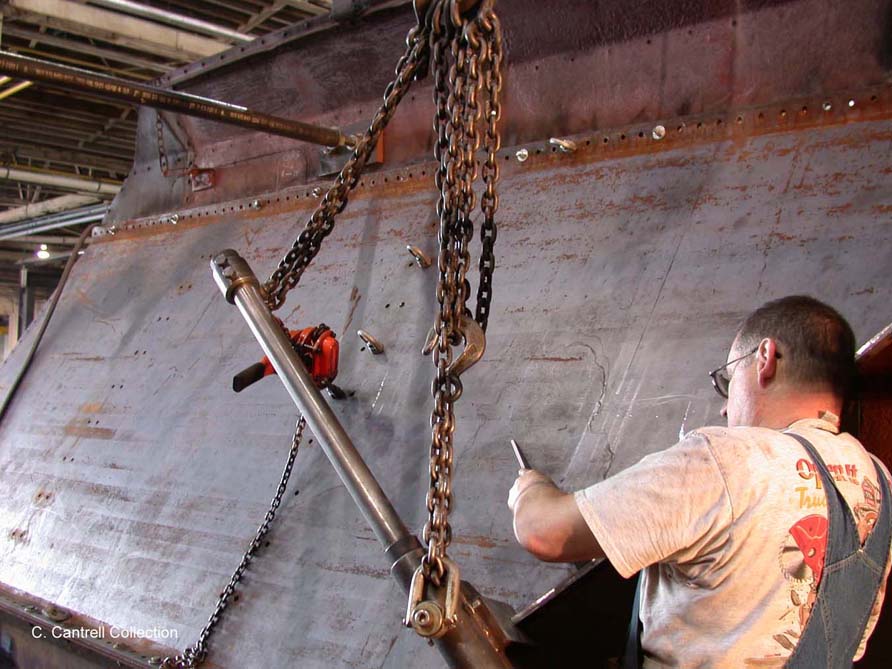 |
Volunteer Walter Elvidge checking new angle of side slope sheet lip after bending. The slope sheets required re-bending due to improper angle of the lip. Seen in the photo is the tool fabricated by the contractor to do the bending. Assisting Walter in the bending process were Charles Cantrell and the contractor. The re-bending of the two sheets took two full days to complete. |
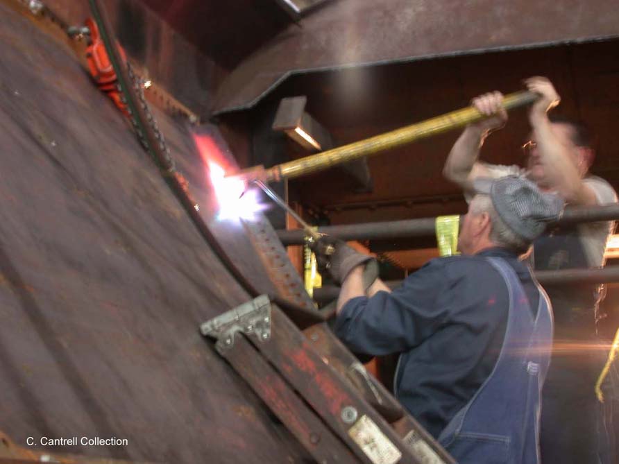 |
Due to the interference of the tenders curved side sheet, a torch was required to heat the lip to facilitate bending. | 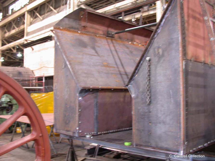 |
. View showing the front of the tender. The sheets are nearly completed with all corners fitted properly. |
Stay tuned for additional photographs of the PRR K-4s #1361 Restoration!!