


This page illustrates and describes the previous original and "NECST" generations of Tomix control and wiring systems, plus items from the current "Neo" system that are already retired. Controls and cords for turntables, working railway signals and so on are generally not included. The years of production are listed to the best of my ability and information sources.
Click here to see images and descriptions of present control system items.
The original Tomix line of controls, in the 5001-5011 series, features green cases. Connections are made by inserting stripped and tinned wire ends into push-release terminals. Tomix uses green 2-wire cables for AC and brown 2-wire cables for the DC track power. Points/turnouts use an AC 3-wire system (red, blue and yellow) from the control box to the points. Extension cables have bare wire ends at one end and a push-release terminal block at the other.
 |
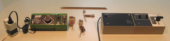
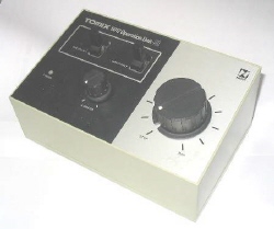
5001 Power Unit (1976-after 1977) - Input: 100 VAC 12 VA 50-60 Hz. Outputs: 0-12 VDC 0.3 A (dial control, center off, with directional indicator lights on either side) with tan push-release terminals, and 17 VAC 0.3 A with green push-release terminals. This original Tomix basic power unit has a small green case with a black sloped top. Note the lettering and the three-pointed design on the dial top. It has a lower volt-amp power rating than its replacement below, and does not seem to have a power switch or a circuit breaker. Tomix also sold the yellow Tomy 6600 power pack in the early years. |
 |
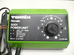
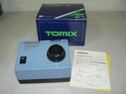
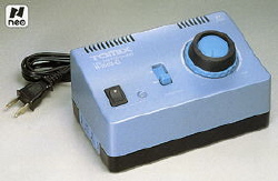
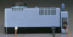
5001 New Power Unit (by 1980-1998) - Input: 100 VAC 16 VA 50-60 Hz. Outputs: 0-12 VDC 0.3 A (dial control, center off) with tan push-release terminals, and 17 VAC 0.3 A with green push-release terminals. This version is far more common than the original version above, and probably replaced that one early on. Contains an on/off rocker switch, push-reset circuit breaker, transformer, bridge rectifier, wire-wound rheostat, and two red directional indicator LEDs to the left and right of the rheostat dial. Note the revised lettering and the textured dial top with square notch. The unit does not say "New" but its blue cardboard box does. |
 |
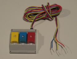
5002 Point Control Box (1976-1998) - Compatible green-cased control for electric points/turnouts. These boxes stack outward in a row from either side of the power unit, held in place by black plastic clips that mount under the cases. Each box has two green push-release input terminals and comes with a short two-wire green cable. These cables "daisy-chain" down the row of boxes to finally reach the AC output of the power unit. Each box has three push-release terminals (red, blue and yellow to match the cables) for attaching wires from the points/turnouts. The toggle handle is made to look like a real switch throw handle with a mounted circular target. |
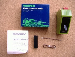 |
5003 Universal Switch Box (by 1980-1998) - This piece is similar in appearance to the Point Control box, but has a regular toggle handle, two tan input push-release terminals, and two red and two blue output terminals. It can be wired to provide control for block reversing, block on/off and reverse-loop situations. |
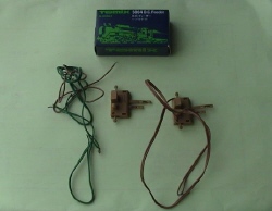 |
5004 DC Feeder (1976-1981) - Connects power unit 0-12 VDC output to track. Features a brown two-wire cable with bare wire ends at one end and a clip with two unequal-length prongs that slide under and contact one rail each on track pieces molded with recessed ballast near the center of the piece. This original version has a miniature push handle on each side for push-release terminals for the lead wires. Cast in brown plastic to match original Tomix brown track. This feeder was replaced by the 5014 version. |
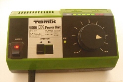 |
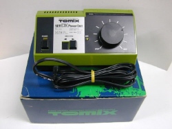
5006 DX Power Unit (1988-1998) - Input: 100 VAC 16 VA 50-60 Hz. Outputs: 0-12 VDC 0.7 A (dial control) with tan push-release terminals, and 17 VAC 0.3 A with green push-release terminals. Similar to 5001, but housed in a longer small green case with black sloped top. Differences include a power indicator LED built into the on/off rocker switch, pushbutton direction control, a continuous control dial without center off position, and a seven LED (5 green and 2 red) power level indicator bar above the dial. |
 |
5011 DX Power Unit (1984-1987) - Same input and output specifications as the later 5006 listed above. Outwardly and functionally similar to 5006, but the 5011 has a push on/off power switch with a separate green LED power indicator light above it. Note that this unit predates the similar 5006 above. |
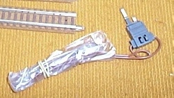 |
5014 NEW D.C. Feeder (1982) - Connects power unit 0-12 VDC output to track. This version has small square push-release terminals on the two-prong track clip, and it is cast in grey plastic to represent trackside apparatus. Replaced the 5004 and was itself replaced by the 5024. |
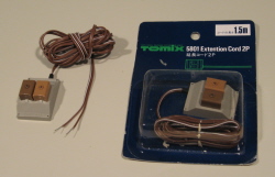 |
5801 Extension Cord 2P (1985-2001) - Extends the 2-wire track power connection. Features a 1.5 meter brown two-wire cable with bare wire ends at one end and a putty-colored terminal block with tan and brown push-release terminals at the other end. These cables lingered on in Tomix catalogs after the rest of the system had been withdrawn. |
 |
5802 Points Extension Cord 3P (1985-2001) - Extends the 3-wire connection from points/turnouts to control box. Features a 1.5 meter three-wire (red/blue/yellow) cable with bare wire ends at one end and a putty-colored terminal block with red, blue and yellow push-release terminals at the other end. |
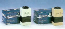 |
5901 A.C. Converter A (1984-1991) - Input: 110-130 VAC 65 W. Output: 100 VAC. Converts nominal 120 VAC commercial power with dual blade plug to 100 VAC for Japanese power units. 5902 A.C. Converter B (1984-1991) - Input: 220-240 VAC 20W. Output: 100 VAC. Similar to 5901, but converts from higher 220-240 VAC commercial power with dual pin plug. |
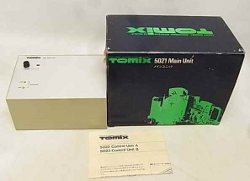 |
5021 Main Unit (1982-1985) - Input: 100 VAC, 50-60 Hz. Outputs: 12 VDC with red and black push-release terminals, and 17 VAC with green push-release terminals. This is a central power supply unit to provide power to other components. It features a pushbutton on/off power switch with red LED indicator alongside, plus push-reset breakers for both AC and DC outputs. |
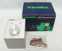 |
5022 Control Unit A (1982-1985) - Input: 12 VDC from 5021. Outputs: One 0-12 VDC output fed from a center-off control dial. Two LEDs indicate direction. Held against 5021 with a plastic clip underneath. (See center item in photo, between 5021 and 5023.) |
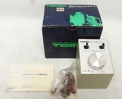 |
5023 Control Unit B (1982-1985) - Like 5022, but with Off-Max. control dial and two toggle switches for separate direction control of two DC outputs. Uses the same plastic clip. |
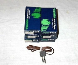 |
5024 DC Feeder SP Type (1982-1998) - Connects power unit 0-12 VDC output to track. This simplified version has the track prong clip permanently attached to the 2-wire 45 cm long brown cable. The cover is cast in grey plastic. There appear to be two versions of this basic design. One has silvery metal contact strips and the plastic cover has a pebbly texture, while the other has phosphor-bronze contact strips and a smooth texture on the plastic cover. |
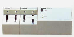 |
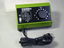
5025 Point Selection Unit (1983-1985) - Controls two points/turnouts with two toggle switches, taking power from the 5021. (Two units shown with 5021.) |
NECST, pronounced like "next," is an acronym for "N-gauge Electronic Control System of Tomix." Introduced in about 1989, the NECST control system offered much-improved power units over the rheostat-based original system, but retained the same basic cabling methods with bare wires and push-release terminals. Like the earlier 5021-series, the cases are larger and squared off, with a sloped top. The cases are putty-colored with black tops with silver accents. NECST units and packaging are marked with a stylized "N" logo with "NECST" below it.
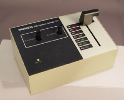  |
5015 Transistor Controller DU-1 (1986-1998) - Input: 17 VAC from 5040 (using included cable with white nylon connector). Outputs: Two 0-12 VDC, each with forward/off/reverse toggle switch (for handling reverse loop polarity situations) and tan and brown push-release terminals, total 1 A. This is a sophisticated solid state controller that simulates an actual single-handle train control. The lever handle has seven positions, each with an LED next to it. The center position (yellow LED) is neutral, maintaining a steady voltage level. Down from this position are three levels of acceleration (slow, medium and rapid), with one, two or all three green LEDS lit. Upward from the neutral position are two rates of deceleration (braking), with red LEDS acting similarly. The third upward position is an emergency brake; in this position, only its red LED is lit and the voltage goes immediately to zero. In operation, you pull down to accelerate the train at a chosen rate, then return to the neutral position to maintain that speed, then select a braking rate to slow or eventually stop the train. Includes a push-reset circuit breaker and putty-colored plastic plate with round lugs that holds the box from underneath to the side of the 5040 box. |
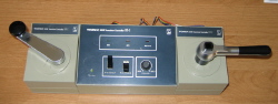 |
5016 Transistor Controller DU-2 (1987-1998) - If the DU-1 is sophisticated, then the DU-2 is even more sophisticated. It is a long three-box unit with replicas of older separate controller and brake handles at the left and right sides. Like the DU-1 it has a 17 VAC input from the 5040 Adapter Unit and two DC outputs with separate forward/off/reverse toggle switches, total 1 A capacity. It has four controller handle positions, with a small dial for setting min/max simulated momentum on acceleration, and four brake handle positions including emergency (immediate stop). Unlike the 5015 DU-1, when in "coast" position the train will gradually lose speed. LEDs indicate power (green), coast (yellow) and braking (red). |
 |
5017 Operation Unit-CL (1993-1998) - This is the first Tomix power unit with the CL (constant lighting) feature. Like the other NECST units, it takes power from the 5440 similar to the 5015. It has a dial control instead of a lever or handles, two DC outputs with separate forward/off/reverse toggle switches, a small dial for adjusting the constant lighting feature and a push-reset breaker. |
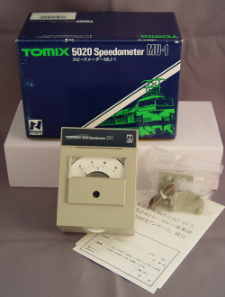 |
5020 Speedometer MU-1 (1989-1998) - This compatible box contains a voltmeter plus an adjuster thumbwheel. It includes alternate dial scales for 0-15 V, 0-160 Km/h and 0-300 Km/h (for shinkansen fans). It has input (red and black) and output (tan and black) push-release terminals, a putty-colored case and an attachment plate. It comes with a short 2-wire brown cable, so that it can be inserted into the output cabling between a controller and the track to indicate voltage or "speed." |
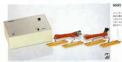 |
5030 Shuttle Operation Unit (1985-1987) - This automatic control unit takes power from a power supply and controls train speed and direction, plus up to two AC points/turnouts. It uses up to four included track sensors (on 70 mm straight track pieces) for activation. It has four modes of operation: back and forth on single track, back and forth with two-track terminal and two alternating trains, back and forth over a crossover (Z-shape), and an oval with passing siding with two alternating trains in opposite directions. |
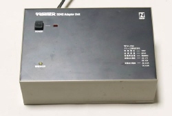 |
5040 Adapter Unit (1986-1998) - Input: 100 VAC 25 VA, 50-60 Hz. Outputs: 17 VAC 0.4 A with green push-release terminals, two 12 VDC 0.6 A with white nylon receptacles, and an unswitched 100 VAC 400 Watt receptacle. Another central supply unit to provide power to NECST control components. It houses a transformer and converts commercial power into various outputs. |
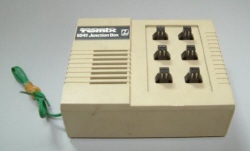 |
5041 Junction Box (1986-1998) - This box contains an 17 VAC to DC converter and allows up to six railway block signals to be plugged in. |
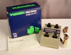 |
5042 Divider (1986-1998) - This unit takes a DC input and allows up to four railway block signals to be plugged in. These units can be daisy-chained to handle more signals. |
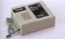 |
5550 TCS Converter Box (1993-2001) - Input: 17 VAC. Output: 12 VDC 1 A. This unit converts AC accessory power to DC power with connectors to support the introduction of early TCS cabling for signals and the automatic grade crossing. |
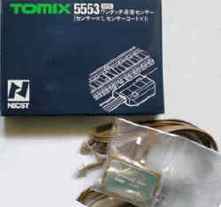 |
5553 TCS Track Sensor (1993-2001) - The first TCS track sensor, for use in activating the automatic grade crossing. Cast in brown plastic. |
The following items from the current "Neo" system have been retired.
 |
5501 Power Unit N-500 (1997-2007) - Input: 100 VAC 50-60 Hz. Outputs: 0-12 VDC 0.5 A (dial control, center off); and 12 VDC on left side for stackable points/turnout control boxes. This unit also has an on/off power switch and a power/fault indicator LED. |
  |
5502 Power Unit N-1000-CL (1997-2009) - Input: 100 VAC 50-60 Hz. Outputs: 0-12 VDC 0.7 A (dial control, forward/off/reverse toggle) with CL constant lighting outer ring adjustment dial; 12 VDC 0.2 A for TCS; 12 VDC 0.3 A on left side for stackable control boxes. This unit also has an on/off power switch and a power/fault (green/red) bi-color indicator LED. It contains no power transformer, being fully electronic, and has quick-acting fault protection, reset by turning the unit off and back on. Its actual output is reportedly 20 kHz 12-volt square pulses with Pulse Width Modulation (PWM) to control the average voltage level. This power form can light the train while stopped, while still providing speed control. It provides excellent slow speed control, but reportedly can damage some DCC decoders. Replaced by similar-looking 5506. Note: In July 2007 Tomix issued an electrical product recall for 5502 units built in May and June of that year, although they stated there was no problem in normal use. Affected units have serial numbers JF06501-JF10820 (on back of case). Lot numbers (on lower left of package barcode) include 20JF for 5502 packages, 51YJG for units in 90144 EX 485 Basic Set, and 59YJG for units in 90943 My Plan DX Set. |


