


TUESDAY NITE CHOIR BOYS ORIGIN
TUESDAY NITE CHOIR BOYS CLINIC #8
Timing
Tuesday Nite Choir Boys started with the first meeting May 18 1993.
The final meeting was #146, March 14th 2006 (13 years).
The move of the STR to BC was the reason for the discontinuing of the meetings of the Group.
It was a time to sit down and talk technical for a couple of hours which we never seemed to do before.
This was an informal group of Railroad Modellers with a variety of hobby backgrounds and experience. Some were long time Model Railroaders and others were beginners. They were from the Waterloo Region area and over time some stayed and others left and new people arrived. The purpose was to sit down as a group and discuss Model Railroad Subjects of interest to members present. Some were preplanned subjects from a list of potential items. Others were curent needs of ongoing members work. Meetings were held at the STR shops and on 2nd Tuesday Evening of each month.
The purpose was to help all the members with learning the technical and skill side of Model railroading. It was to share the shortcuts and avoid the time loss of the past pitfalls. Model Railroading is the most diversified hobby there is as far as skill and artistic needs are concerned. It takes a great number of hours to build a larger layout and anything that makes it more efficient and easier to do and still obtain a good level of results is worth some time spent talking, investigating and testing ideas. This is really helpful for the new modeller in the planning stages and in the beginning of collecting materials, equipment and building a layout. It helps engineer a layout which can be larger, more reliable, trouble free and lower cost, without frustration, disappointment and abandoning the hobby.
Mtg #1 - May 18, 1993 - attendees - John Orendi, Chris Savage, Cecil Spurgeon, Bill Ackland
We generated the original subject list for future meetings. We put priority on some of the categories.
1. Wiring: - General - Panels - Power Supplies - Priority 1
2. Track Planning General - Railroad Concept - Priority 2
3. Painting - Buildings - Cars
4. Decaling
5. Loco Power Trains
6. Scratch Building - Structures - Plastic - Wood
7. General Questions - Problems Current - 15 minutes per session
8. Scenery - Hard Shell
Discussed - Track - Blocks, turnouts, rev blocks, channel control. This was to explain from the history of layout wiring the original throttle (battery or power pack) per block system through cab control to today with DCC.
The understanding of these systems and the progress to today allows the new builder to select the system he wants for his concept and level of financing for the electrical construction. He can determine his needs for a running layout vs an operational layout. The discussion covered parrallel 2 wire system to the track vs common rail and then the feeder system for DCC. What does it mean for a reversing track block, wye or turntable. How to wire a turnout for control, track wiring, DCC wiring, block control, signals control. How to wire for DCC with feeders, reverse blocks and circuit protection.
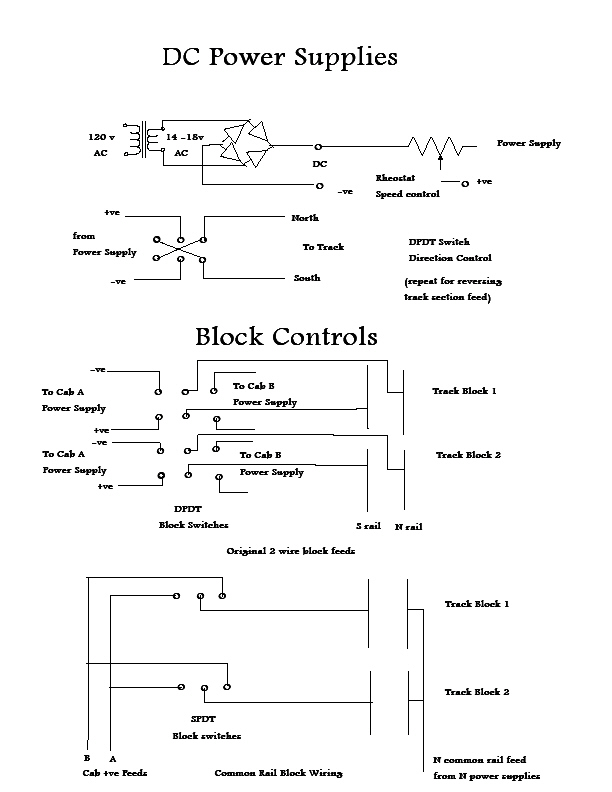
Originally in 1940's the power source for model railroads were car batteries. The speed control was rheostats. The reverse was a knife blade DPDT disconnect. It was obvious why they put a controller (rheostat and DPDT switch) on each block and powered all from 1 battery. If you ran the block you have a 50-50 chance of a short at the joint. This meant that through trains had to have each block preset for speed and direction before the train was handed off to the next engineer at the adjoining block. This was a hugh communication job on a large layout. When 12 volts and power packs (running from hydro) came along the same wiring was used and the power packs were added one per block. The next step was to run 2 wires from the 2 rails of a block to a block switch (DPDT) and then wire this to 2 separate power packs so that the blocks could be selected by the engineer on each power pack. By using higher multiple pole switches a number of power packs could be added. This became the original cab style control but the blocks were assigned to each engineer by a central dispatcher panel. This allowed one engineer to control several blocks with one power pack. The developement of a route cab rotary switch allowed the engineer to select his own blocks (block he is in and one ahead) and pick them up as he went forward and dropped the block behind. With these rotaries interlocked only one engineer at a time could hold his block. This was truly cab control. The bacic layout with 2 cabs and DPDT block switches became very popular with small layouts and 2 operators. The next step was common rail as the separate cabs were then wired with SPDT switches and controlled the south rail only. The north rail was the common rail and was wired to all power packs and a common bus wire. This also allowed the north rail to be gapped for signal blocks separately from the power blocks on the south rail. With common rail the reversing blocks had to be 2 wire connected through a separate DPDT switch to match polarities at each end of the block (or turntable). With the developement of DCC the wiring we reverted back to 2 wires, one for each rail north and south, fed at intervals (usually every rail piece) to common north and south bus wires. The south bus wires can be segmented for short circuit protection and identification. The north bus wire can be segmented for signal purposes.
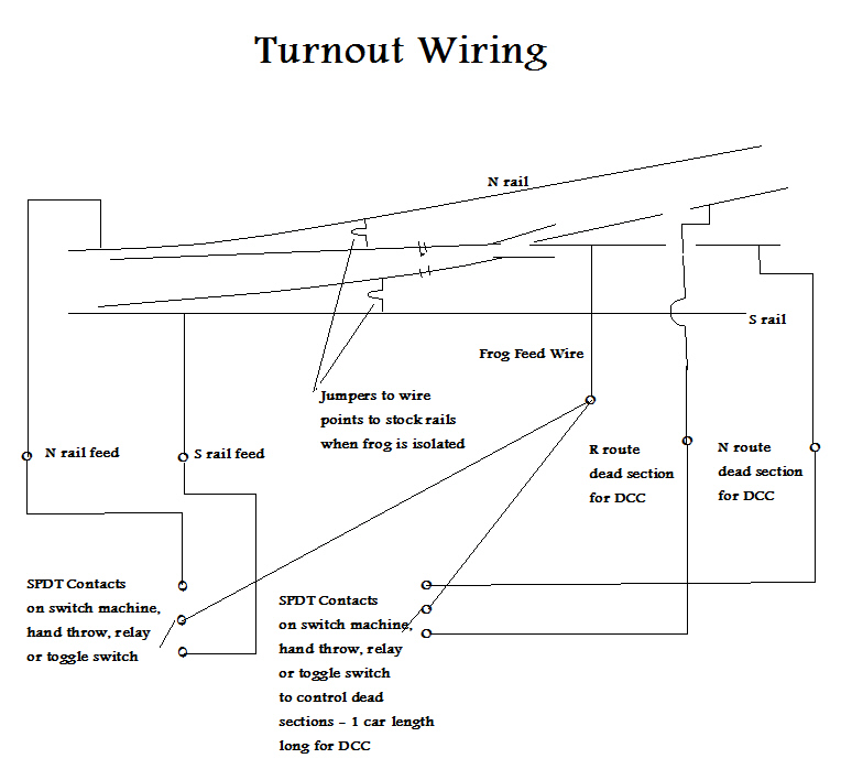
Turnout wiring involves several circuits for different electrical functions. The primary wiring is to control the turnout machine that throws the points. This is either a toggle switch or a push button type of control. The toggle switch control is usually a DPDT type controlling a motor machine. The push button control is usually for a 2 coil solenoid machine. There are also diode matrix circuits which feed the machines from a selection of push buttons on the panel which select routes rather than individual turnouts. Sometimes rotary switches and one push button are used. Also an electric wand with contacts on the panel are used. push buttons amd matrix circuits can be used on motor machines with relays in the circuits. The "X" block selects its power from the route block selected therefore a separate block switch is eliminated for the "X" block section.
The second part of the turnout wiring is the frog itself. Originally the frog was part of the point system. The points contacted the stock rails on either side and enegized the frog accordingly. This was not reliable as the points not always contacted the stock rails properly. The points also had to have a greater throw (wider gap between the stock rail and the point to prevent shorts on the back of the wheels) and this loaded the switch machine more. A wired frog is the most reliable system. The points with less throw can be wired to the stock rails with less throw and the frog is electrically independant. The switch machine or manual throw needs a SPDT function to select the stock rail power appropriate for the frog. This is also better than a dead frog with DCC wiring. The continuity of a live frog provides a more reliable power feed to the equipment passing through it.
The third part is any block wiring that the turnout is related to needs a DPDT function for each block related to the route on either side of the turnout. The wiring of an "X" block can be controlled by the turnout involved in the "X" block route. The power to a relay to controlling a reversing block can be run by another SPDT function on the turnout control. With DCC it is advisable to wire dead rails beyond the turnout for each route to prevent short circuits. A SPDT function can control this as well. This allows the dead rail to be powered from the frog on the selected side of the route. Passing track blocks can be energized on DC wiring with a SPDT function on the turnout machine there by eliminating the need for block switches.
The fourth part is signalling. Turnouts change routes and therebye need to change signals accordingly. A SPDT function on the machine or control can select the signal cicuit for the route selected.
The fifth part is the panel light system. A SPDT function can handle the control of the red and/or green bulb or led in the related panels. The wiring in a ladder track location can be cascaded from one machine to the next to setup the panel light logic and light the appropriate track light on the ladder.
The use of a 6PDT relay on a turnout machine will handle all of the functions discussed above. Very often a 4PDT is enough depending on how many of these functions you require.
DCC requires 2 main bus feeds around the layout so that all rails can be jumpered to either the North or South appropriate bus wire. The main bus wires are connected to the booster for the layout. Can be segmented for either circuit breaker protection and /or separate boosters on a larger layout. The main bus wires need to be fairly heavy wire (#18 or #16 for smaller layouts and #14 or #12 for larger layouts) especially if you are feeding switch machine control, lights and other accessories all from the DCC power source. The jumpers from each rail or electrical section, depends on the continuity and conductivity being very secure and having no poor connections or resistance losses. If your rails have good jumpered joints then a bus feed for each piece of rail is not necessary. But if you have long runs of rail in each electrical section on a larger layout then a feeder every 6 feet or so would be necessary. The feeders should be as short as possible and can be #20 or #18 wire. Make sure all solder or terminal joints are well done and electrially sound.
Power Supplies:
Throttles - Capacitor Discharge - Lights - Relays - Signals - Building Lights
Track:
Blocks - Turnouts - Reverse Blocks - Channel Control
Panels:
track Blocks - Turnouts - Lights
Other Items:
Throttles - diode Matrix - Panels Lights - Turnout Machines - Signal Circuits
©
Enjoy Model Railroading
Bill Ackland MMR


