Please allow about a minute for the animations to download
Note: These images are not thumbnails.
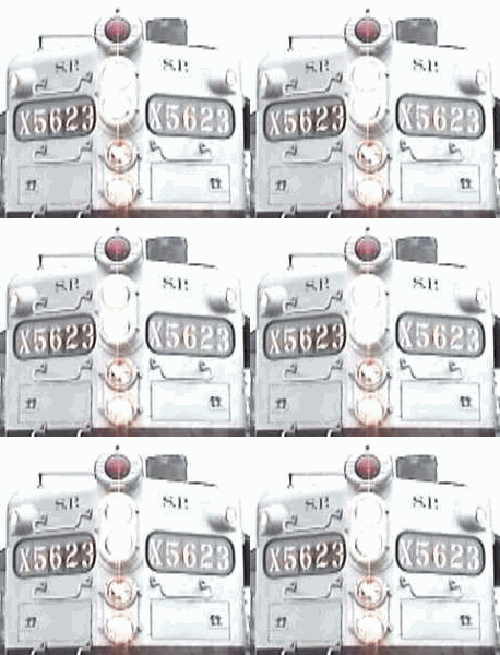 |
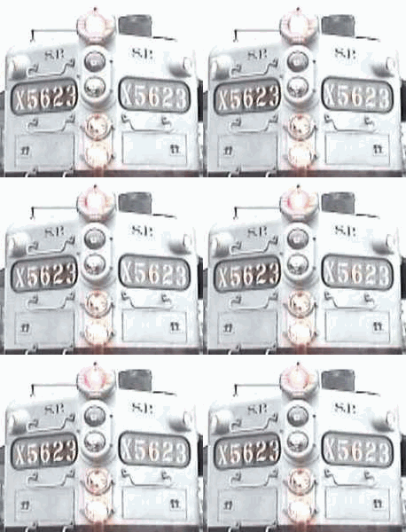 |
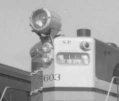
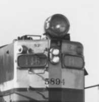
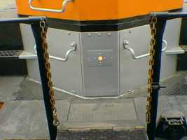
It has been said that the Southern Pacific designed a light package and then found a locomotive to fit it. They were not terribly consistent though as evidenced by the difference between the first 4 passenger geeps (5600-5603) and the last 4 (5621-5625). Even the freight geeps wore differences, depending on purchase dates. 5621 -5625 also sported number board access doors on both ends, unlike the 5600-5603.
 |
 |
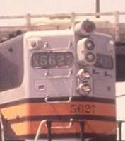 |
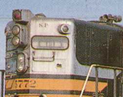 |
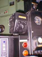
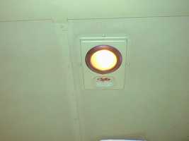
In the cab, there are 4 switches that affect the
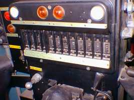
lights. First, there is the "Signal Light" breaker which turns the entire
system on or off. It is 6th from the right in the first photo. Next, there
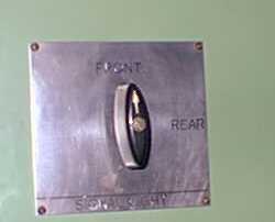
is a 2 position switch which selects the lights at either "Front" or "Rear"
of the locomotive. It is located behind the engineer, within reach on the
rear cab wall. Next, there is a control box at the engineers station with
2 switches. One is rotary with 4 positions which are marked "Off", "Red",
"Dim" and "Bright". Dim and Bright refer to the white lights only. Lastly,
there is a toggle switch (on the side of the box) marked "Run", "Off" and
"Inch" which controls the motor in the selected white Gyro light. Either
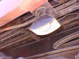
of the white Gyros can therefore be used as an auxiliary headlight by positioning
the motor so the light pattern is vertical and turning the motor off. There
are 2 ways to turn on the red light. With no pressure (or less than 40
pounds) in the train line and the "Signal Light" breaker turned on, the
red light will be running on both ends. When the train line pumps up to
more than 40 pounds, the red light will go out and if the rotary selector
switch is in either "Dim" or "Bright", the white Gyro light will illuminate
on one end. It is possible to turn on the red light on one end only by
using the "Red" position of the rotary switch but it will always oscillate.
If the train brakes go into emergency, the train line pressure goes to
zero. The 40 pound switch turns off which ever white light was on and turns
on both red lights. The red warning light in the left photo will be on
when either red oscillating light is on. The yellow light indicates that
the sanders are operating.
 |
 |
 |
 |
 |
 |
 |