


The Basic GP9
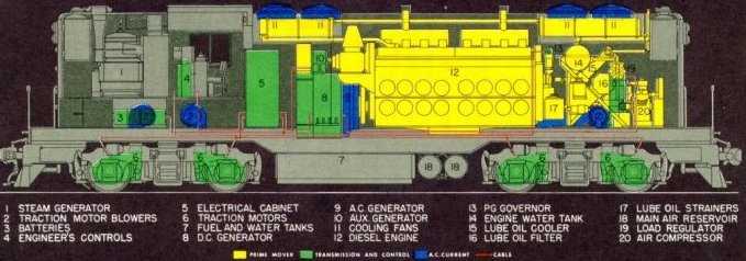
This drawing is of a pre-1959 GP9 as later versions
had 2-48" radiator fans rather than 4-36" fans. It does not have dynamic
brakes but with the air tanks under the frame, it is externally more representative
of SP5600 through 5603.
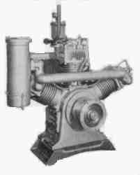
EMD 567C Engine
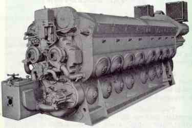
This is the front end of an EMD engine and faces
the rear of the locomotive. The main generator is mounted to the far end,
next to the cab. The square box to the left is part of the oil filtration
system. The governor is mounted vertically, between the snail-like water
pumps.
Auxiliary Generator
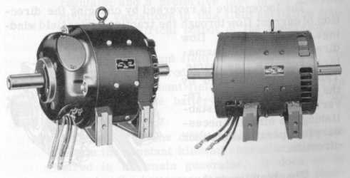
On the left is the standard 10,000 watt battery
charging generator. The 5623 is equipped with the optional 18,000 watt
generator because of the demands of the steam generator.
Main Generator
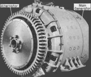
This view of the main generator is from the end which attaches to the flywheel on the engine crankshaft. The alternator is a variable voltage, variable frequency AC generator which is used to power the locomotive engine cooling fans and the 4 traction motor blowers. The generator is a DC machine with battery field excitation. While warning labels on locomotives normally say something like, "Danger 600 Volts", the generator is perfectly capable of putting out upwards of 1000 volts DC. It is also used to start the diesel engine by connecting the batteries to a special starting winding within the generator.
Typical Traction Motor

This drawing is representative of all EMD DC traction
motors. The gear on the right side is called the pinion and in our case,
has 15 teeth. It engages with the large gear pressed on the axle. The hole
just forward of the pinion is where the axle passes through the motor housing
and contains bearings on the left and right sides. The ear shown just forward
of the left hand axle hole is used to support the cover over the pinion
and axle gear. The four wires shown consist of 2 armature cables (A and
AA), and 2 field wires (F and FF). In the left rear corner of the top of
the motor is the hole where the traction motor cooling air is passed to
the motor interior.
 |
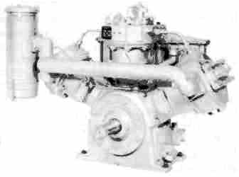 |
While these two Westinghouse air compressors have the same output capacity, the Model WBO tends to be more reliable because of the water cooling. That is, of course, unless one runs the engine out of water or lets the locomotive sit around in freezing weather. These are 3 cylinder, compound compressors. They have 2 low pressure and 1 high pressure cylinder. The low pressure cylinders take in atmospheric air, raise its pressure about 5 times and exhaust to the high pressure cylinder which boosts the pressure again. A locomotive runs a nominal 130 to 140 pounds in the resevoirs, depending on the railroad operating practice.
Steam Generator
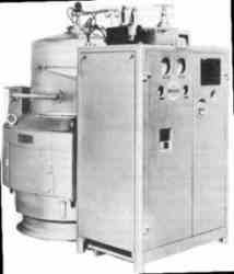
This photo shows the complete Vapor model OK4625
steam generator. The square box contains all of the control mechanism while
the cylindrical part is the boiler. With one of these in the nose of a
locomotive, there is little room for anything else.


