Almost all EMD locomotives have what is called an
Equipment Rack. It is a collection of parts that are not exactly part of the
engine but serve the engine systems. Included are the fuel pump, fuel filters,
oil filters, water expansion tank and oil cooler.
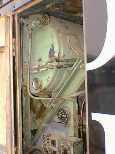
This view is from the engineer's side
of the rack. The tank at the top is the cooling water expansion tank. When
the engine is not running, water drains out of the radiators and into the
tank. At the top of the tank is a valve called the "G" valve. This valve is
opened when adding water to the system in order to prevent an air lock and
to tell when the proper level has been reached. At the bottom of the tank
is a temperature gauge and below the tank to the right is the oil pressure
gauge.
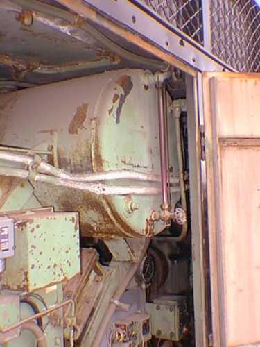
This is the view of the tank from
the other side of the door. Here, you can see the water level sight glass
which looks like a vertical pink strip. This is the color of the borate water
treatment compound we use to inhibit rust and corrosion.
The cylinder near the top of the photo
is the Michiana oil filter housing. It contains 4 oil filters, each about
6" in diameter and 3 feet long. Oil is pumped from the engine oil pan, through
a strainer (part of the "ice cream freezer" mounted to the engine block),
though the the Michiana filters, to the oil cooler and back to the pressure
side of the strainer housing where the pressure pump then picks it up and
forces it into the engine. There are actually 2 pressure pumps but more will
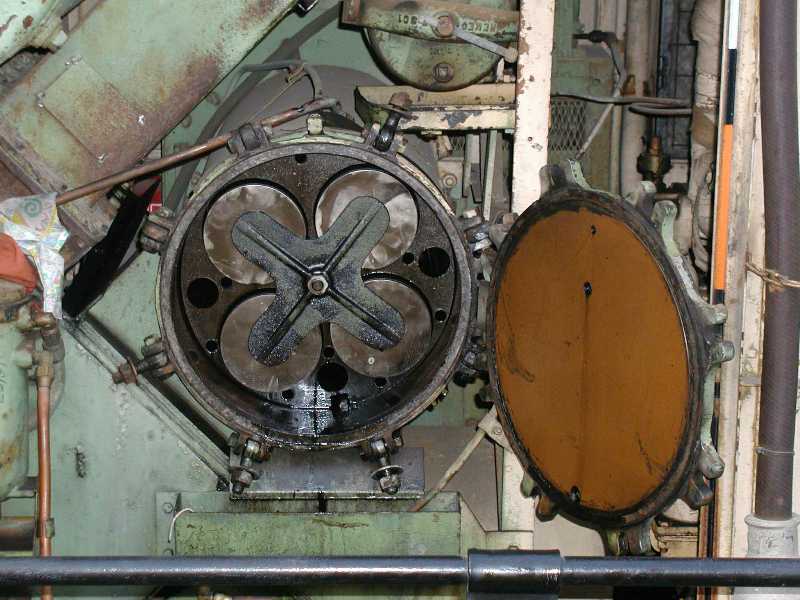
be found on that subject in the engine section. The right hand photo
shows the housing with the door open. The 4-leaf clover shaped piece
holds the 4 filter elements in place against their rubber seals and the housing
plate..
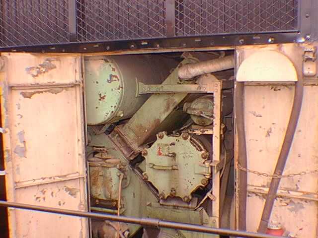
From this angle on the fireman's side,
one can see the relationship between the oil filter housing and the water
expansion tank. Between them, laying at an angle, is the oil cooler. The
pipe exiting it at the top and pointing to the right is the water line to
the rear radiators. The rack on the right hand door is for the storage of
the rear MU cable. The small cylinder above the Michiana housing and to the
right of the oil cooler is an additional fuel filter which the S.P. installed
but we do not use.
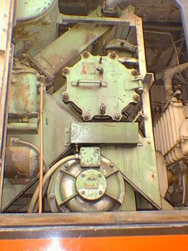
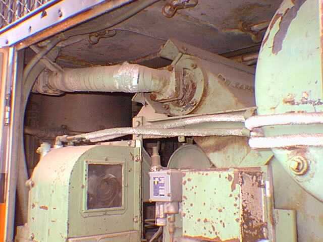
The oil cooler is a little less visible
on the engineer's side, but the outlet connection to the radiators is easily
seen. Below the elbow is the top of the load regulator, discussed in the electrical
section. The two horizontal pipes running across the center of the photo
are the oil lines which connect the governor to the load regulator.
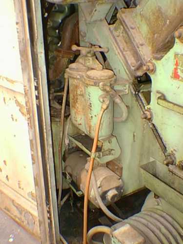
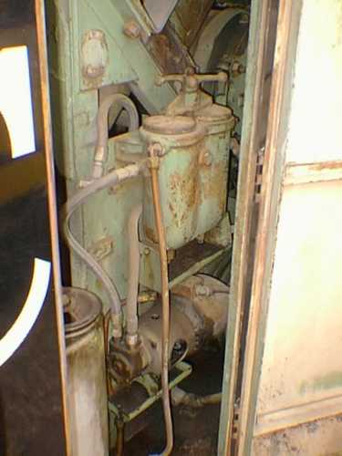
At the bottom of these photos is the
fuel pump and above it, a dual element fuel filter. The pump sucks fuel from
the tank through one filter (the right side) and then pumps it through the
filter element in the left side to the engine where it is filtered further
(further filtered?) by the spin-on cannisters mounted to the block.