The 5623 is powered by an EMD, 16 cylinder, 2
cycle, 1750 horsepower diesel engine. Being a 2 cycle engine means that
each cylinder fires every time it comes to the top of its stroke. So, in
one revolution, the engine fires 16 times which is why EMD's sound so smooth.
If one considers the cab end of a Geep to be the front end, the engine
is mounted in the locomotive backwards. The rear of the engine is the end
attached to the main generator and that, as we know, is next to the cab.
Why, you ask? The high voltage connections are much shorter this
way. With very few exceptions (really old Alcos come to mind), all diesel
electric locomotives are built this way.
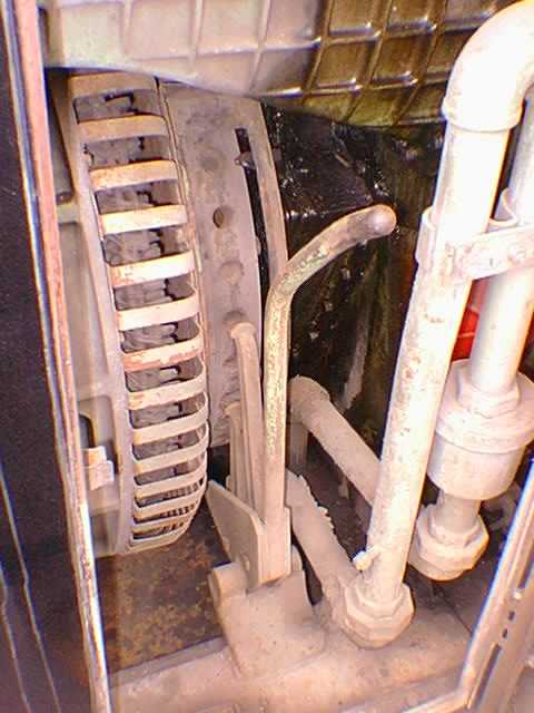
There are times when it is necessary
to turn the engine over by hand. Setting the valves and injector timing
requires precise positioning of the crankshaft for each cylinder. Inspecting
the pistons and liners for wear and checking the piston rings also necessitates
turning the engine manually. The bar shaped affair in this photo is called
an "engine jack" or "baring tool" and has ears that engage with holes in
the flywheel. Pushing the handle down causes the crankshaft to turn 4 degrees
and pulling it up, another 4. So, it takes 90 strokes of the jack to turn
the shaft over one revolution. This can get to be work.
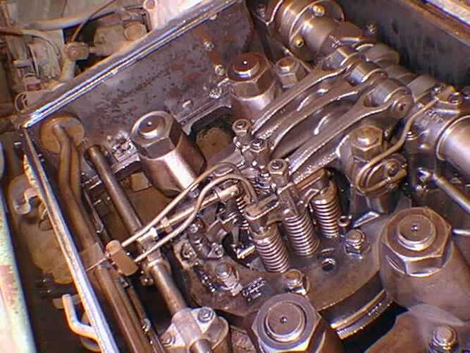
Each bank of cylinders has 1 camshaft,
driving 24 cam followers. There is one follower in the center of the cylinder
for the injector and, on either side of that, 1 follower activating 2 exhaust
valves each. The connecting link between the injector rack and the lay
shaft rack can be seen along with the adjustment nuts on the link. The
nuts are for adjusting the injector rack position which controls the amount
of fuel delivered to each cylinder each time the cam follower drives the
injector plunger down.
This is the view inside the left
hand airbox with the number 9 hand hold cover removed. You can see the
intake air ports in the side of the cylinder liner. By cranking the engine
by hand to the proper position, the piston rings can be made visible for
inspection through the ports. The large horizontal pipe in the photo is
the water manifold that carries cooling water from the pump. Each cylinder
has a jumper pipe that connects from the manifold to the liner. Cooling
water flows from the manifold, through the liner, up through the head and
then out through a jumper into the block.
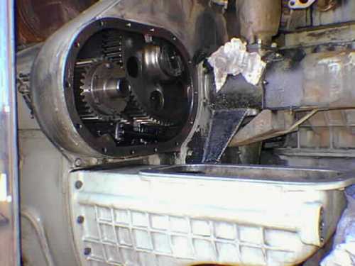
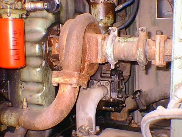
This is what the blower mount looks
like. The photo was taken on the Alameda Belt Line #44 at the time I was
changing out a blower. When the seal on the input shaft gets old, oil from
the gear train housing gets sucked into the blower and burned in the cylinders,
one of the causes of a condition known as "puking". The drive gears for
the blower and camshaft gear are visible in the photo. The blower bottom
housing leads to the "air box" which is pressurized by the blower and from
which fresh air enters the cylinders when the piston reaches the bottom
of its stroke.
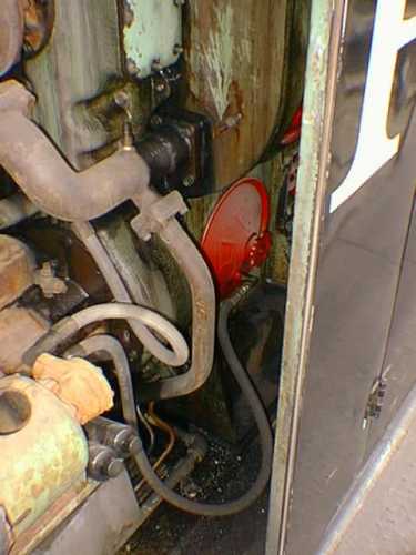
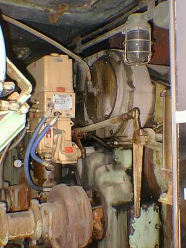
The rear of a roots blower is about
all one can see as most of it is hidden behind a body panel. The silver
colored box above the blower is one of the 2 dry element air cleaners found
on the intake of each blower. The tube exiting the rear cover drains excess
oil from the gear train inside the blower. The other photo is of the ABL
#44 during the blower replacement and shows clearly the blower mounting.
This motor drives an oil pump which
is used to pre-lubricate the engine. Since the 5623 sits for extended periods,
I installed the arrangement to fill the oil galleries in the engine and
insure that it was fully lubricated on startup. The pump sucks oil through
a pickup tube in the number 9 cylinder crank case inspection cover and
pumps it through a check valve into the oil pump outlet elbow. The pump
is controlled by a pressure valve which turns it off when engine oil pressure
reaches 4 pounds.
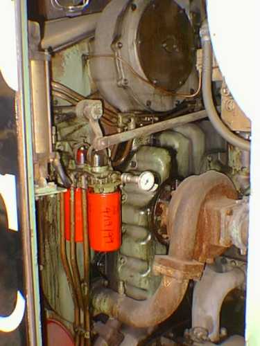
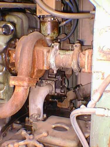
These views of the right side of
the block (locomotive left) show the 2 spin on fuel filters and the right
hand side water pump. The rod just above the center of the left hand photo
is the connection between the engine governor and the right bank of injectors.
The suction elbow between the ice cream freezer and the intake side of
the lube oil pressure pump is also visible.
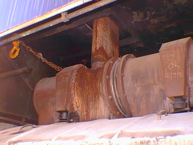
There are 4 mufflers (called "stacks")
on the engine, each handling the exhaust from 4 cylinders. The stacks are
joined in pairs with each pair exhausting through the carbody roof. The
front and rear stack pairs are mounted pointing opposite from each other.
Each stack has a cleanout port to allow the removal of accumulated carbon
trapped by cyclonic baffles inside the housing.
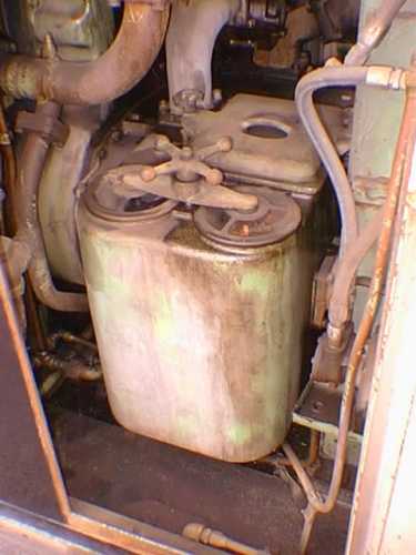
This is the "ice cream freezer",
so called because of its shape. It is actually 2 separate oil filters in
one housing. The square cover toward the rear is in the suction side of
the system and the 2 round covers are in the pressure side. There are no
"elements" inside the housing, just a screen strainer under each round
cover. The primary function of these filters is to catch nuts or bolts
or errant engine parts and prevent them from destroying the teeth in the
engine oil pressure pumps. Just below the water pump and to its right is
the engine lube oil pressure pump. This is actually 2 pumps in one housing.
One part supplies the engine lube oil and the other the piston cooling
oil through what are called "Pee Pipes".
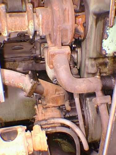
In the upper part of the left photo,
is the left bank water pump. Below that, in the center of the block, is
the lube oil suction pump. At the top of the front of the block, is the
engine governor. It is connected via rods to the injector racks on each
bank. The vertical handle is also connected to these racks and is used
to assist in engine starting. An electrical connection is on the other
side of the governor top.