The 5623 has 3 distinct electrical systems. A
set of 8, 8 volt batteries provide the 64 volt low voltage system, an alternator
built in to the main generator provides the 3-phase AC needed to run the
engine and traction motor cooling fans and the main generator supplies
the high voltage for the traction motors. Note: References are occasionally
made to a locomotive having a 72 or 74 volt low voltage system. In fact,
when the engine is running, the charging voltage applied to the batteries,
from a properly adjusted voltage regulator, is 72 volts DC, measured at
the battery switch. The regulator output is actually set at 74 volts because
of a dropping resistor between the generator and the batteries.
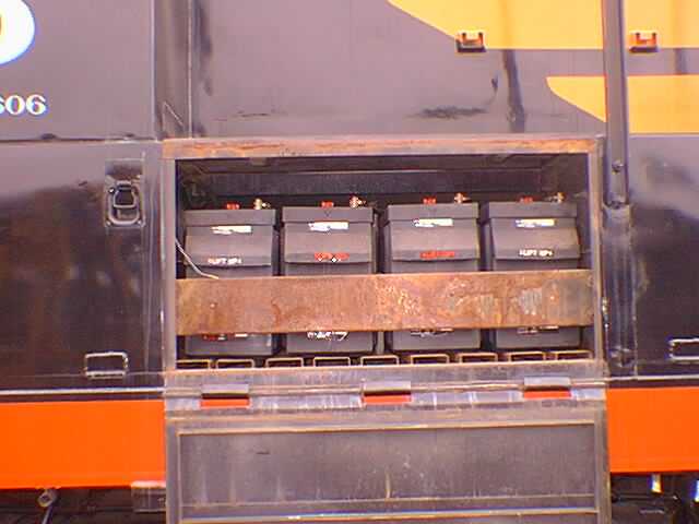
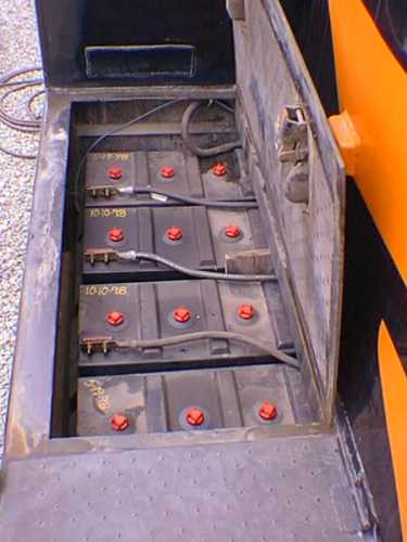
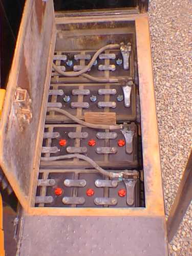
These are the battery compartments.
There are 8 batteries in the locomotive, 4 on each side. Each battery is
28" long, 11" high and 18.5" deep. They weigh 418 pounds each and at this
time in 1999, cost $3780 for a set. They are no fun to change but are removed
by sliding them out the side of the box.
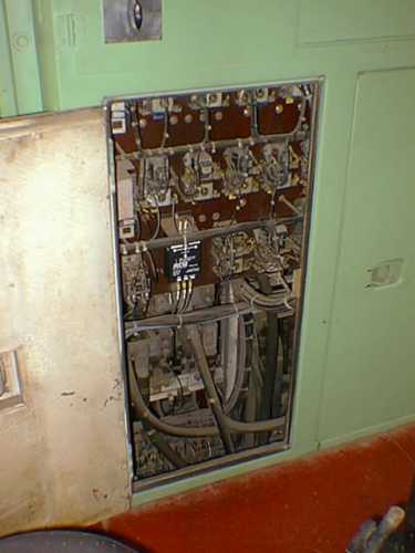
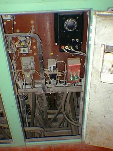
There are 3 electrical cabinets
in the rear wall of the cab. Their contents do not match a stock GP9 because
S.P. relocated almost everything during the GRIP rebuild. In the upper
right corner of the center cabinet, there is a battery trickle charge that
I installed. If the 5623 had dynamic brakes, the center cabinet would be
a good deal more complicated.
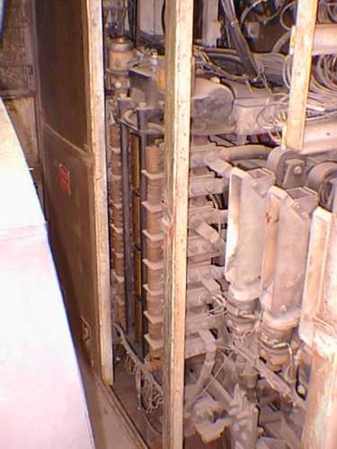
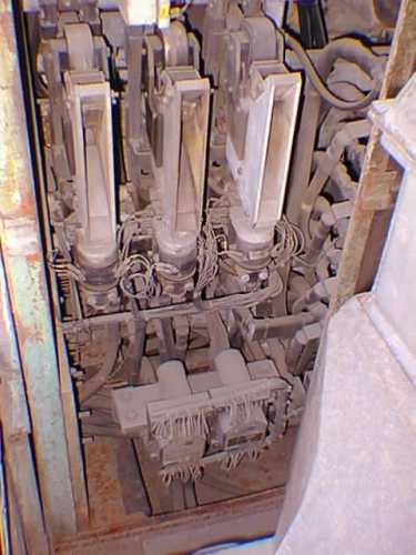
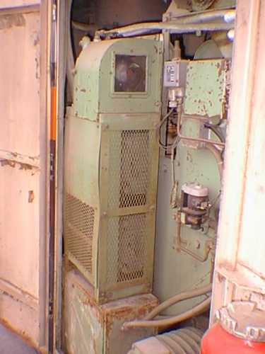
On the opposite side of the wall
from the photos above, are 3 cabinets containing the reverser (2nd photo),
power contactors, transition circuits,miscellaneous relays and a LOT of
wire. This is not a typical GP9 as S.P. had their own ideas on how to do
things and where to put parts. However, the reverser and power contactors
are in their stock locations.
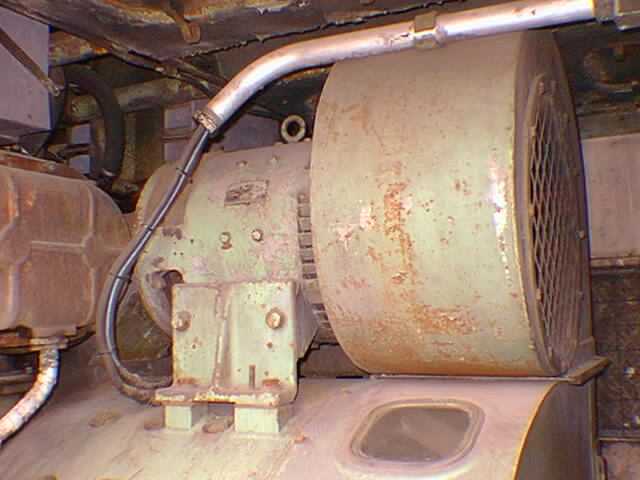
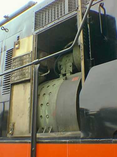
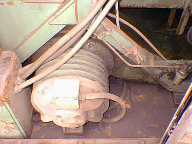
The auxiliary generator serves the
same function as the alternator on your car. It charges the batteries and
more importantly, provides the electricity to operate all the systems on
the vehicle while the engine is running. The 5623 has a 18KW version because
of the steam generator. Gp9's are usually equipped with a 14KW unit. The
main generator cooling blower is attached to the free end of the generator
armature.
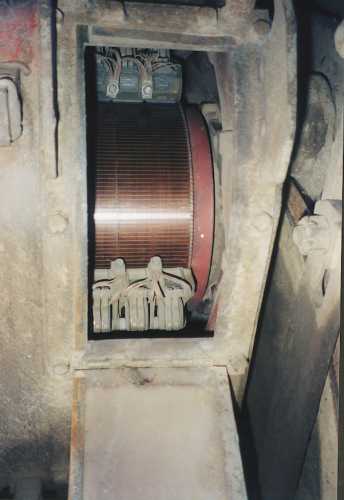
The alternator is 16 pole, 3 phase
machine, built intgrally with the main generator. Its output varies with
engine speed. The frequency is about 106 hz at 800 rpm and 36 hz at idle.
The voltage is about 208 at 800 rpm and 75 at idle. It receives its excitation
from the auxiliary generator through a set of slip rings on the free end
of the main generator armature. Since the alternator is part of the generator,
it is a bit hard to photograph, but this photo shows the location of the
stator windings, next to the engine flywheel. Connection is made to the
stator on the engineer's side, near the bottom of the generator.
The main generator is connected
to the rear of the diesel engine by a flexible plate coupling, bolted to
the engine flywheel. The generator is a DC machine with 12 brush holders,
6 negative and 6 positive. There is a winding built into the generator
which, with battery voltage applied, causes the generator to revolve in
the proper direction, cranking the diesel. The generator can put out over
1000 VDC and is capable of delivering about 6000 amps.
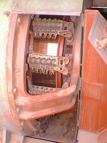
This is the view looking straight
up into a traction motor with the lower inspection cover open. Two of the
four brush holders can be seen. Each holder has 3 brushes. The GP9s were
built with EMD model D37 motors but they were upgraded to the D77 specification
during GRIP. This was done so that they were interchangeable between any
S.P. locomotive application.
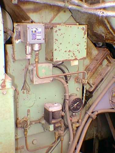
This collection of parts controls
the air compressor. At the top left is the pressure sensitive switch that
is adjusted to the compressor operating range. On the S.P., this was set
to stop pumping at 140 pounds and start at 130 pounds. Some railroads use
120-130 pounds. These are the usual settings, as the FRA mandates that
the main reservoir pressure shall be at least 15 pounds above the brake
pipe pressure. In passenger service, the brake pipe is usually set to 110
pounds and thus, the 130/140 pound setting, while in freight service, the
brake pipe is (west coast) normally 90 pounds.
The purpose of the load regulator
is to control the loading on the diesel engine. It is nothing more than
a hydraulically driven rheostat in the circuit between the batteries and
the battery field in the main generator. The engine governor controls the
rotary position of the rheostat based on the fuel demand of the engine.
If the engine begins to require too much fuel for a given rpm, the governor
will cause the load regulator to insert more resistance in the battery
field, thus decreasing excitation. The governor will attempt to keep the
load regulator at the highest excitation setting possible. The story is
a whole lot more complicated that this, like what happens when the engine
is at idle or during wheel slip or transition, but that's the general idea.
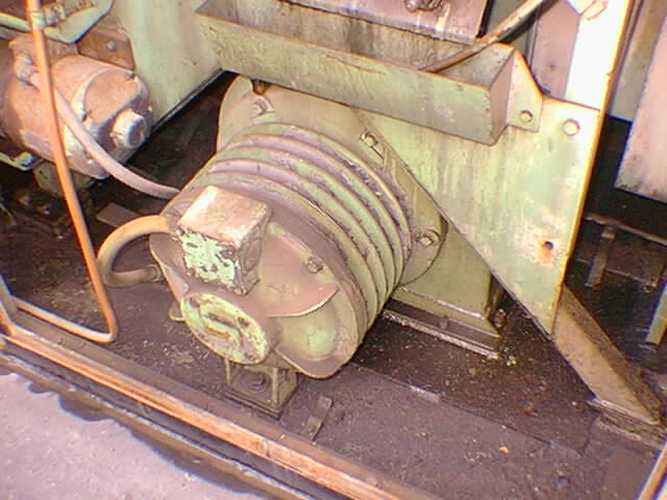
These are the rear traction motor
blowers. The near photo is the engineer's side and the other, the fireman's
side. In the near photo, the duct leading forward to the number 3 motor
can be seen. These motors are 3 phase, 4 pole, 5 HP, 3100 RPM (at full
engine speed) induction type. The front blowers are under the cab floor
and a bit hard to photograph.
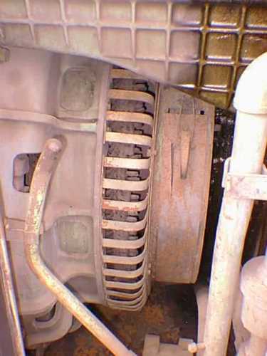
This is the underside of a radiator
cooling fan. These motors are 3 phase, 8 pole, 9 HP, 1550 RPM (at full
engine speed) induction motors. The fans are numbered 1,2,3 and 4 from
the short hood of the locomotive. The fans do not all turn on at once but
rather in a temperature controlled sequence. Number 1 turns on at 165 degrees,
then #3 at 168, then #4 turns on and the rear shutters open at 171, and
finally, the #2 fan turns on and the front shutters open at 180 degrees.
The hot engine alarm will ring at about 208 degrees.