


All 8 of the S.P. and 4 of the T&NO passenger geeps came equipped with dual controls. They had duplicate controls on each side of the cab so the locomotive could be run comfortably in either direction. For a 360 degree view of the cab, taken by Trainweb at Railfair '99, click here. Use your back button to return to this page from Trainweb.
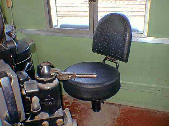
This is the engineers seat. What else is there
to say about that? The handle sticking out in the left lower corner of
the photo is the automatic (train) brake.
 |
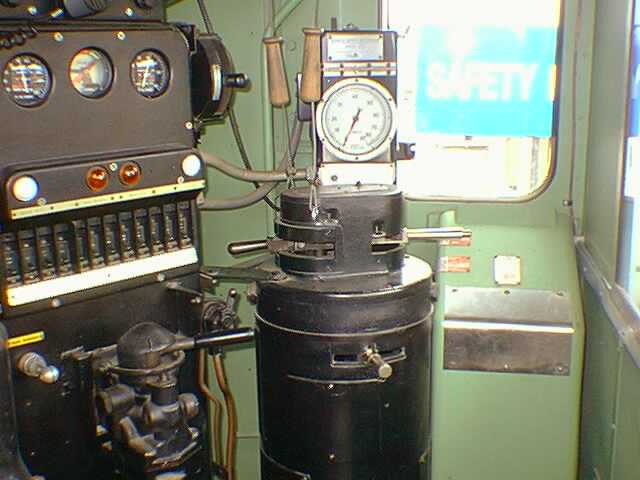
The 5623 is equipped with the "drum" type controller
found on EMD locomotives since the 1930's. It was not until about 1959
that the "AAR" control stand replaced the drum and the stand to the left
of it. The drum contains the selector switch (top left), throttle (top
right) and reverser (center). The selector switch had many functions over
the years but now, it is mainly used to control the strength of the dynamic
brake - which the 5623 does not have. The box to the right of the controller
is the engineer's cab heater, installed during the GRIP upgrade in 1977and
behind the controller is the Barco mechanical speedometer.
 |
The control stand has, at the bottom of the photo,
all of the switches required by the lights and the control of the locomotive.
The row of colored lenses are warning lights for various purposes and the
gauges are for the main air reservoir and brakes. At the left top is the
Gyrolight control and below it, a couple of indicator lights for the red
warning light and the sanders.
 |
On top of the control stand is the ammeter which,
by the way, shows the current being consumed by 1 traction motor. On top
of the ammeter is the non-original 96 channel radio. A telemetry (FRED)
receiver is mounted on a bracket to the right of the ammeter. The two wooden
handles visible to the right of the stand are for the horn. One valve admits
air through the horn through a restriction (choke) and gives a muted horn
sound.
 |
 |
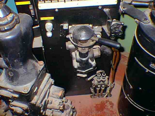
Below the switches is mounted the independent
(engine) brake valve. To its right is the bell valve and to its left is
the sander switch. The valve near the floor is called a "dual ported cut-out
cock" and is used to test the independent brake system.
 |
This is the fireman's side, where the other control
stand
used to be. To the left is the other cab heater. To the right is the control
head for our auxiliary radio which we keep tuned to our private channel.
The blue box behind the radio is the water cooler. To the left of the left
hand seat is the fireman's side cab heater. Over the top of the water cooler,
on the right is the conductor's emergency brake valve.
 |
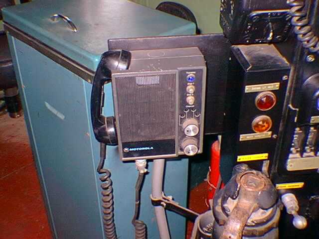
In the center of the photo is the control head
for the original S.P. 4 channel Micor radio. The radio itself is mounted
in the nose. On the right side of the head are, top to bottom, a blue transmit
indicator light, dispatcher tone 1 and tone 2 send buttons, the channel
selector switch and the volume control. Most of the face of the head is
occupied by a speaker, even though the handset includes one. The transmit
button is part of the handset.
 |
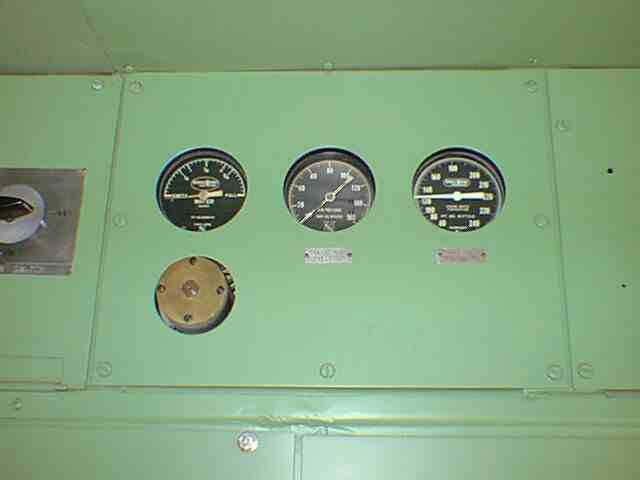
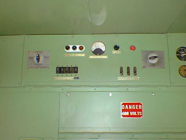
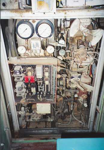
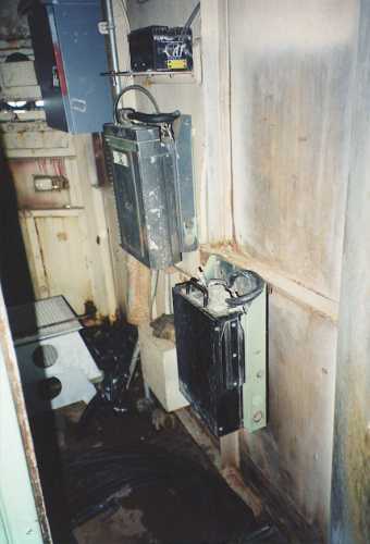
On the cab back wall are mounted a number of gauges
and control switches. These three are boiler water level, control air pressure
and engine temperature. In the other photo are the battery ammeter, alarm
lights, headlight control switch, isolation switch and miscellaneous switches.
 |
 |
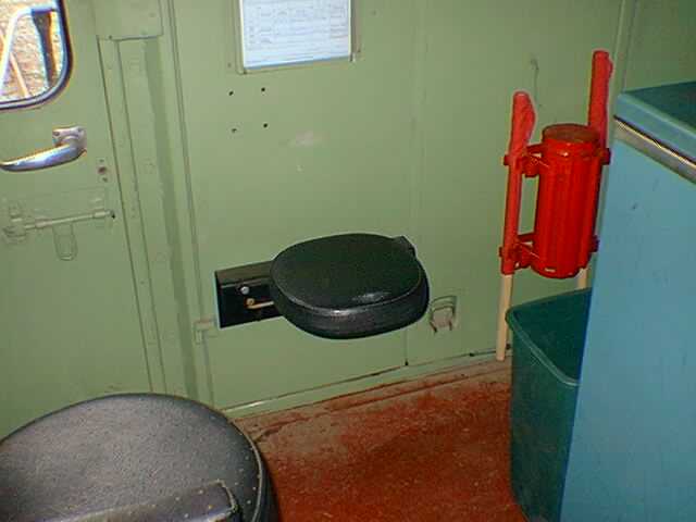
The left photo shows the brakeman's seat and the
fusee (flare) holder. The original seat was removed when the dual controls
were taken out in 1977. This seat came out of a S.P. passenger SD9. Ten
points off for authenticity. The front wall of the cab is occupied by the
access doors to the boiler controls and the door to the nose (on the right).
The two gauges visible are for boiler pressure and steam line pressure.
The all important FRA blue card is in its holder below the gauges.
 |
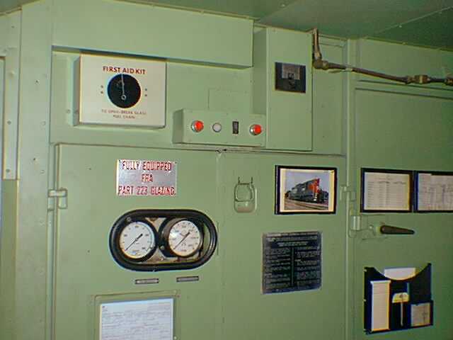 |
Inside the boiler doors are a bewildering array
of gauges, valves, pumps and electrical gadgets. At the top of the photo
are the same two gauges seen in the right hand photo above. The other photo
is taken through the nose door. Nearest the camera on the right is a 72
to 12 volt converter I installed for various uses. Behind and above that
is the Micor radio pack. Above that is a filter system for the telemetry
receiver.
 |
 |
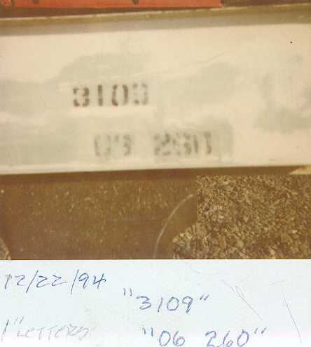
Below is a polaroid I took of the lettering on
a piece of metal from the front cab wall. It is interesting in that
the number "3109" appears. This must have been an error by the stencil
maker during the 1977 GRIP rebuild. When we got the locomotive, the
lettering had been painted over. Locomotive numbers are usually painted
on the cab interior, in view of the crew, so they know which locomotive
they are using.
 |


