


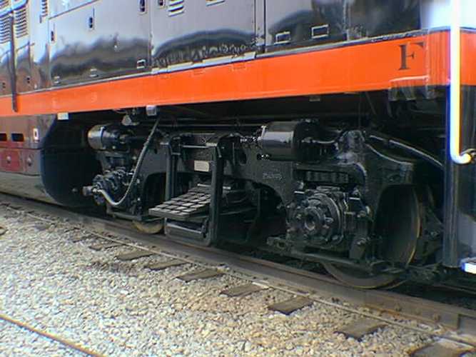
All 8 of the S.P. passenger geeps came equipped
with a custom made pilot on both ends. The T&NO locomotives came with
the standard EMD footboard passenger pilot of the era. I have never seen
an example of our pilot on another railroad. Have you?
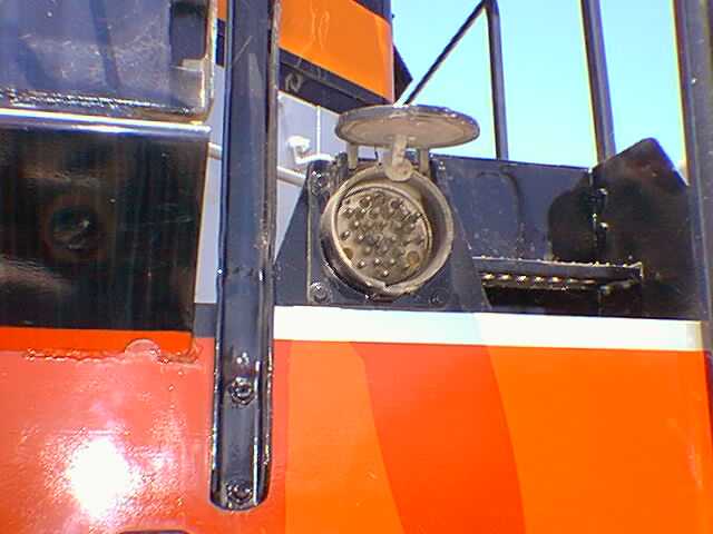
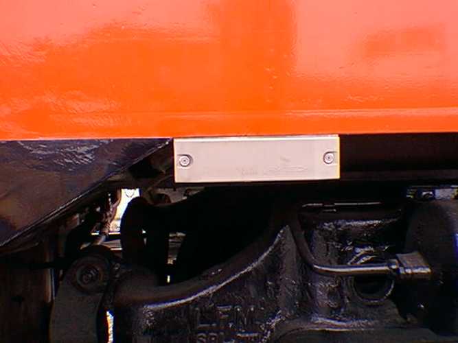
The custom pilot was designed to complement those
found on passenger steam locomotives of the day. The slotted metal plate
over the center of the pilot gives access to the steam line connection.
The plate is held on by 4 very large cotter key type devices and is quite
heavy, being made from 1/4" steel plate. In order to connect a car steam
line, the cover had to be removed and stored someplace. Needless to say,
the covers did not last long and were usually thrown away. Most photos
of the geeps do not show them.
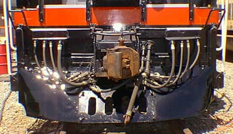 |
Each corner of the pilot has a small step built
in. These were intended to take the place of a regular footboard but are
only large enough for one average size foot so they were probably not too
popular with brakemen. After 1977, footboards and pilot steps were outlawed
by the FRA and a plate was welded over them. A removable cover has been
applied to each step on the 5623 for photographic purposes but the use
of the step is still illegal.
 |
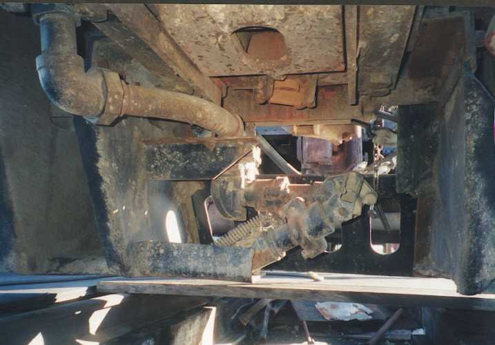
This is the view from underneath the locomotive,
looking out through the pilot. The steam connection is easily seen in the
center of the photograph with the feed line from the generator coming down
vertically in the left top of the first photo. The angular pieces seen
are braces that run from the pilot up to the locomotive frame.
 |
 |
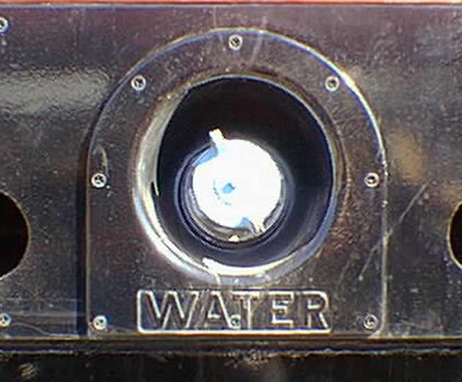
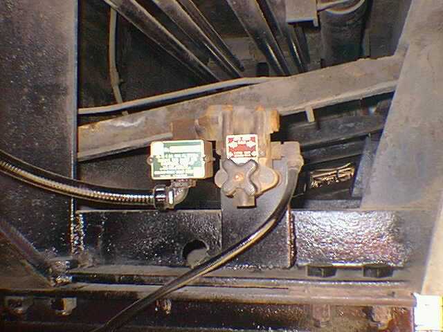
This is the steam line valve, located on each
end of the locomotive, just before the line reaches the pilot. In normal
use, the carman hooking up the cars would make the steam connection and
then carefully open this valve to feed steam to the consist. The other
photo is of the valve handle. The pointed thing in the photo is the engine
water filler.
 |
 |
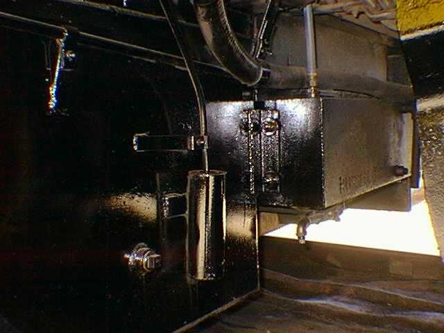
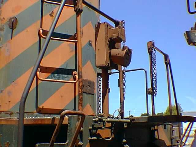
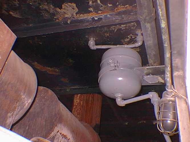
EMD locomotives have a two-cycle engine which
looses oil from the chambers pressurized by the superchargers. These chambers
are known as "air boxes". Normally, they are drained occasionally by opening
a valve on each side of the engine. In order to simplify this process,
we (as have many railroads) installed a retention tank into which the air
boxes can drain at their leisure. The box is attached to the two water
tanks, at the rear end of the locomotive. The blue hose seen coming straight
down into the top of the tank is connected to the air box on the fireman's
side of the engine. There is another one for the other side which cannot
be seen in this view.
 |
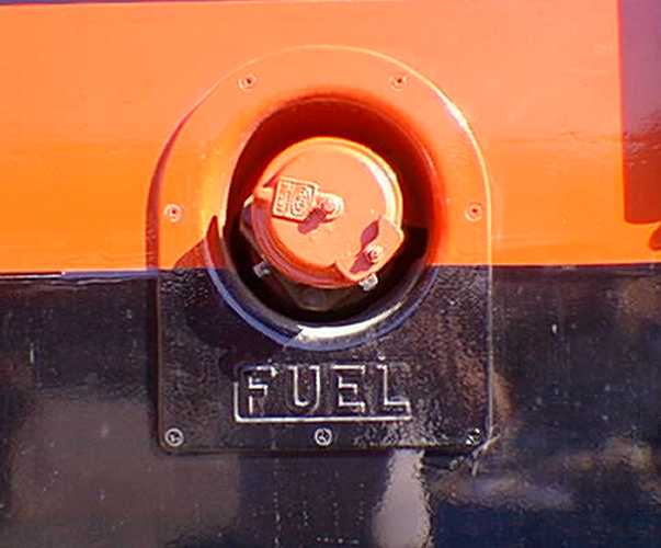
This is the fuel filler neck, one found on each
side. The two fillers connect to one tank, mounted under the center of
the frame of the locomotive. This type of filler is known as a "Snyder"
type because of the brand of the quick-connect hose coupling.
 |
 |
This is the water filler, one found on each side.
Each side feeds its own tank and the two tanks are connected together fore
and aft, at the bottom. The filler neck is a quick connect type but has
no specific name that I am aware of. The tanks have overflow pipes at the
front, under the skirting.
 |
 |
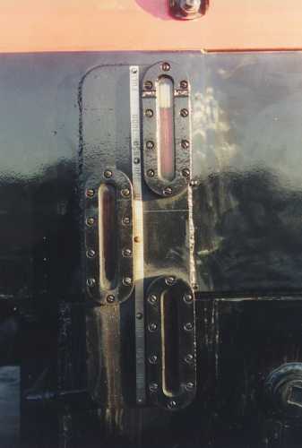
Because the fuel tank on the 5623 is buried under
and up into the frame and between the two water tanks, there are 2 systems
of measuring fuel level. From 500 to 1200 gallons, the level is indicated
by the 3 sight glasses in the photo below. There is an exact duplicate
of these glasses on the other side of the frame.
 |
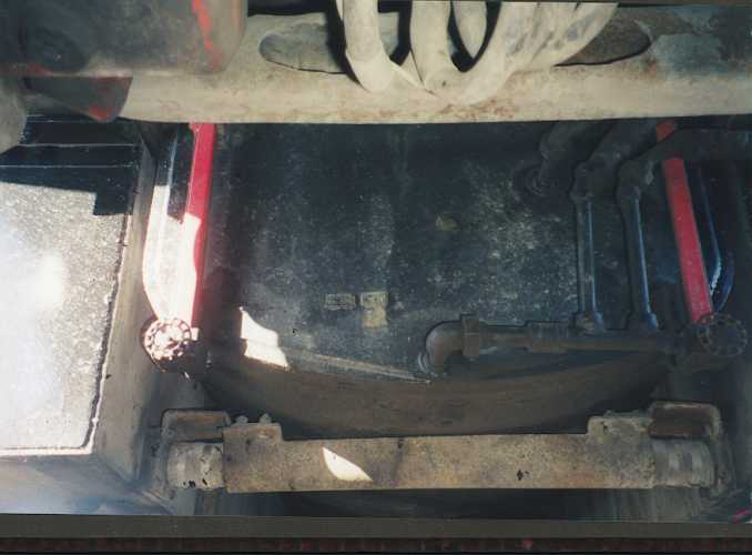
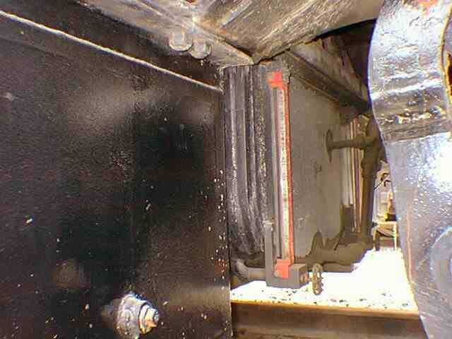
These are views of the front end of the fuel tank
and the 2 water tanks. The red gadgets are the shields over the fuel sight
glasses which indicate the first 500 gallons of fuel in the tank.
There are 2 so the fuel level can be seen from either side. Note that the
fuel tank is a separate piece from the water tank and the 2 water tanks
are connected together by pipes at the bottom
 |
 |
MU (multiple unit) is a term applied to the connecting
together of 2 or more locomotives in a manner by which they can all be
controlled from 1 unit. There are 2 types of connections; air pressure
and electrical. The electrical one is made through a 27 pin connector mounted
to each locomotive. The first photo is of the one on the 5623 (with the
cover propped open with a rock) and the other is of the WP713 which has
dynamic brakes. The square connector is for "Field Loop" and was EMD's
early method of hooking together units with dynamic brakes.
 |
 |
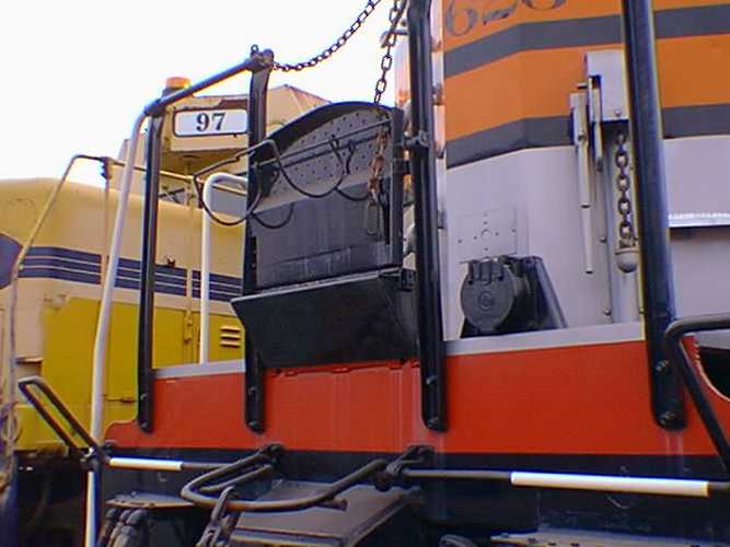
One aspect of MU is the ability to get from one
unit to another while the train is in motion. This may be necessaary
because of the need to reset alarms or check engines while in transit.
Most locomotives equipped with MU have a folding platform on each end of
the frame which allows a crewmember to walk across the area above the coupler.
Note that the platform on the 5623 is raised about 8 inches higher than
the one on the OTR 97. SP did this themselves in order to make the
geeps more compatible with the SD models which have a higher frame.
 |
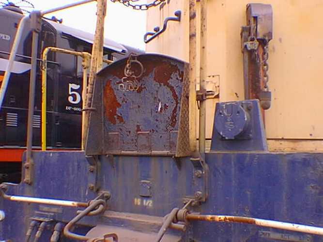 |
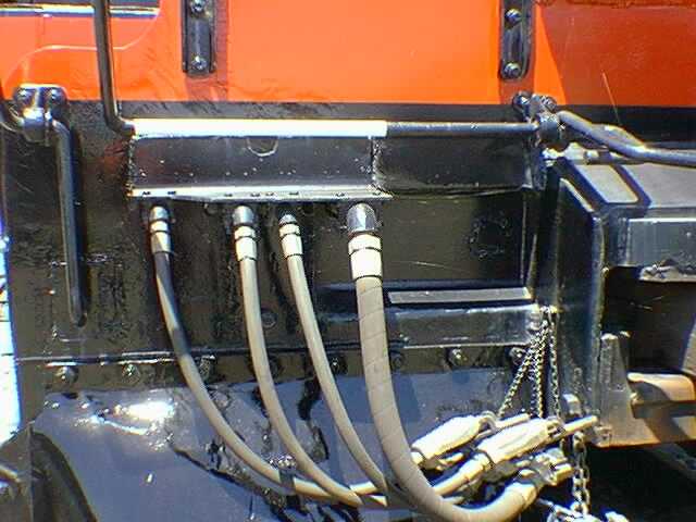
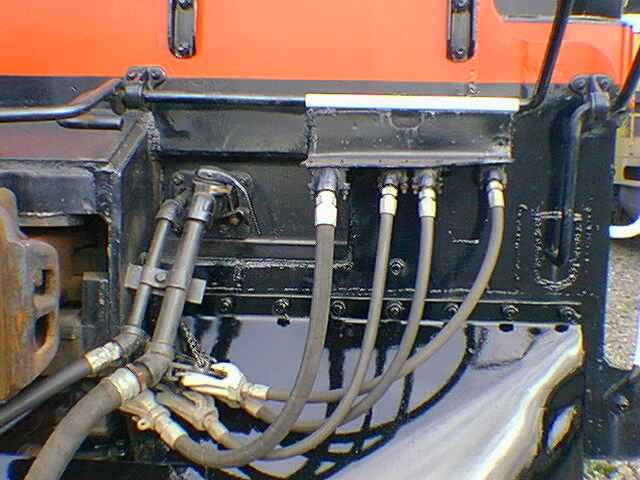
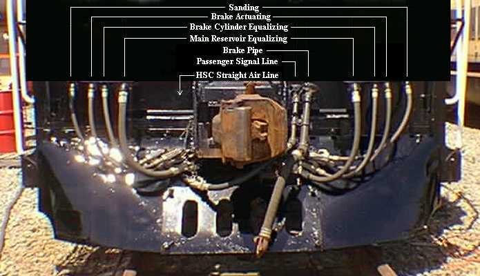
When the 5623 was built, it had a grand total of 13 air hoses on each end. Ten were for MU, two for the air brakes and a passenger signal line. The 5623 currently has 10 hoses as 1 MU hose was removed from each side and the HSC straight air hose was removed when the locomotive was converted to 24RL brakes. The first photo shows the 4 MU hoses remaining on the left side and to the right of them, a patch welded on the end sheet, covering the hole where the HSC line used to be.
Click here for the identity of all the air hoses.
 |
 |
The 5623 is still equipped with the original Barco
mechanical speedometer. This unit is driven by a chain-like cable which
connects to a drive head on the right side of the number 2 axle. A photo
of the Barco speedometer will be found in the "cab" section of "Details".
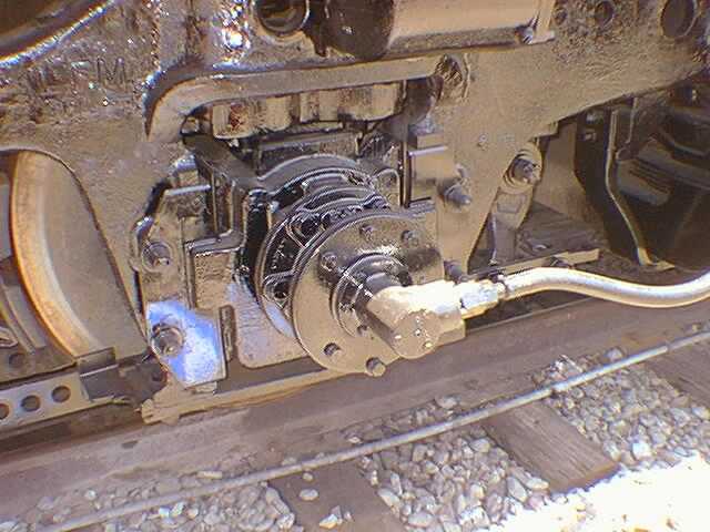 |
The law requires "that any train operated faster
than 30 miles per hour shall have an in-service event recorder in the lead
locomotive". In order to comply, we installed an event recorder and an
additional axle drive was attached to the left side of the number 1 axle.
This drive feeds speed information, which can not be obtained from the
mechanical speedometer, to the recorder.
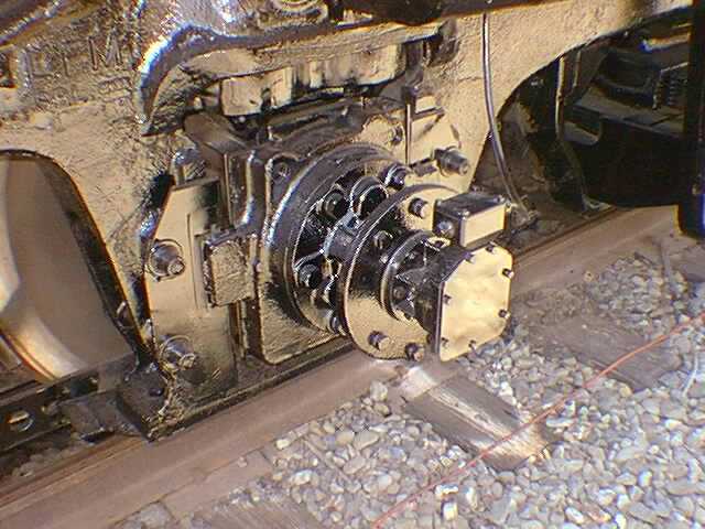 |
EMD trucks of this type are probably the most
common part to be swapped between locomotives. They are interchangeable
front to rear and between EMD locomotives of the same general weight. Both
of the trucks on the 5623 are not original. The front truck is from S.P.
8151, an F7B built 12/49. The rear truck is from S.P. GP9 3621, built in
1957 and rebuilt in Sacramento 3/77 into the 3757. Both trucks were rebuilt
in GRIP 3/77. Welded on plates on both trucks tell the story of these changes.
Interestingly, the rear truck has a rebuild plate from the Los Angeles
General Shops, in addition to the Sacramento plates. Thanks to Steve Wilhelm
for the historical data on the trucks.
 |
This is what is commonly refered to as a "ground
light". There is one on each side of the frame, near the center of the
front truck. Old timers have told me that they are used because it is nearly
impossible to tell when a diesel locomotive is moving a very slow speed
as there is no change in sound. A steam locomotive will give off an occasional
"Chuff" when starting but a diesel will just sit there and grrowl. The
lights give the engineer and fireman a visual reference to the ground.
 |
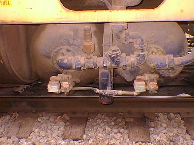
A common noise heard around locomotives is an
occasional heavy, quick exhaust of air. This is caused by devices attached
to the air resevoirs which expell water and gunk from the tanks. The 5623
has two of them, one to drain each pair of tanks. They are mounted under
the frame, at the end of each water tank. The valve handle can be turned
to manually open the drain. These are electrically operated by a timer
while some are operated by the control system for the air compressor.
 |
The left photo is of the ends of the air tanks
on a standard Geep. Note the automatic drain valve on the end of each tank.
The valve picks up water and gunk via a pipe that extends down into the
bottom of the tank. The other photo is of one of the moisture trap tanks
on the 5623. Each "torpedo tube" has a connection at its lowest point and
each pair is piped to one of these tanks which then connect to a drain
valve on each side of the frame, as shown in the photo above.
 |
 |
This is called an "AEI" (Automatic Equipment Identification)
tag. Back in the days of the S.P., we were required to put the devices
on the 5623 so they could keep track of us. It never had them when living
as the 3189. The tags are mounted right front and left rear and identify
their positions as well as the equipment initials and number.
 |
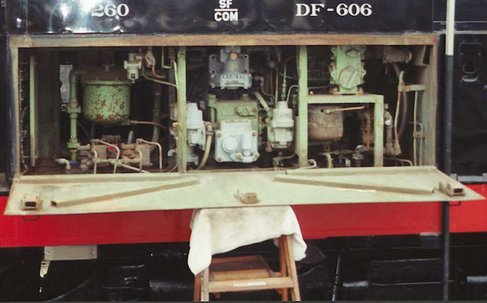
When you opens the door immediately below the
engineer's window, this is what you will see. What we have here are the
vast majority of the air brake control parts in the center and right of
the photo and the air brake filter system in the left. The cylindrical
grey thing on the bottom right side is the control pot for the passenger
signal whistile, located in the cab. Needless to say, all the parts have
names and most of them need to be cleaned or changed out every 1 or 2 years.
This, by the way, is a number 24 brake system.
 |


