


 |
Lynton and Barnstaple Railway Signalling at Lynton |
|
|||||||
|
|||||||||
This page describes the signalling at Lynton station on the former narrow-gauge Lynton & Barnstaple Railway (L&BR). Please see the separate Introduction to L&BR Signalling page for general background information and details of other pages on RailWest about the signalling of the L&BR. Click here for more general historical details about the L&BR and a Bibliography.
Any study of the signalling at Lynton is complicated by the fact that the track layout and associated signalling underwent a number of changes in the first few years of the railway's existence and there is very limited documentary or photographic evidence of the original arrangements. After this initial upheaval the layout remained basically unchanged for most of the life of the railway, except for some updating of the signalling equipment by the Southern Railway (SR) circa-1924. Most of the photographs and diagrams which have been published in books about the L&BR reflect only the later arrangements. Sadly no official signal-diagram for Lynton has come to light yet for any period during its existence, so there remain a number of unanswered questions about the installation.
 |
 |
|
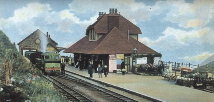
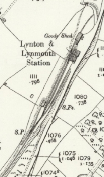
| A view and map of Lynton station in the early 1900s. | ||
The station at Lynton was laid out on an approximately south-west to north-east alignment, with the line from Barnstaple approaching from the south-west. Click here to see a map of the station, but note that this was surveyed in 1903 by which time the crossover at the northern end had been reversed (as can be seen also in the colour image above). Trains ran 'Down' to Lynton and 'Up' to Barnstaple. There was a platform on the east (Up) side of the main line, with the station building at its northern end. The western face of the platform served the main line, whilst along part of its eastern face at the southern end there was a shorter bay road. To the west of the main platform line there was a run-round loop, which was extended at its northern end to form a siding serving the goods-shed situated beyond the end of the platform. The engine-shed lay to the south-west of the station and was served by a separate siding on the west (Down) side of the single line. The point leading into this siding was combined with the point leading into the bay platform road as a double-slip, a rather unusual and complicated piece of trackwork for a narrow-gauge railway.
The original signalling equipment was installed by Evans O'Donnell (EoD), who were the L&BR's signalling contractor. The signal-box (SB) was a small wooden hut, similar in style to those used at the main intermediate stations, which was mounted at the back of the platform between the station building and the end of the bay platform. This might seem to be a strange location, as it was at the other end of the station from most of the points and signals, but it would have enabled the signalman to be employed on other station duties between trains. In common with the other small L&BR SBs the Electric Train Tablet instrument (for the single-line section to Woody Bay) was housed in the station building. In the absence of any official signal diagram for Lynton the outline diagram below is intended to show those features of the signalling which are believed to have existed at Lynton during the first few years of the railway's existence.
Probable features of the original signalling at Lynton circa-1898
Note: the signal and point letters and numbers shown on all the diagrams on this page are purely arbitrary and have been included merely for identification purposes within RailWest. With the exception of points A1 and A2 (see below), any points given the same prefix letter (eg B1, B2) are assumed to have been worked from the same lever.
On 4-May-1898 Lt Col HA Yorke inspected the L&BR on behalf of the Board of Trade (BoT) and his subsequent Inspection Report stated that the lever-frame had 7 levers (6 working and 1 spare); it is assumed that the frame was mounted at the rear of the SB in common with the other L&BR ground-level SBs of this type. At that time the provision of signals was actually less than that which is shown on the diagram above, as it is clear from photographic and documentary evidence that the Down Home (DH) originally had one arm only and that the only Up Starting signal provided was the one for the Bay line (UBS). It is unclear whether this arrangement was intentional, or simply a result of the fact that the installation work was incomplete and still in progress, especially as Col Yorke requested in his Report for "...the interlocking to be completed according to the table shown to me...". Certainly he added the suggestion that "...both the main and bay lines should be signalled for arrival and departure..." and the necessary alterations had been completed by the time of a further Inspection in September that year. The DH can be seen with one arm only in the background of a photograph of the 1898 opening ceremony (Ref [1] page 36) and in later photographs with two arms it is clear that no alteration had been made for the lampman to access the lower arm off the ladder.
L&BR facing points were fitted with 'economic' Facing Point Locks (FPL). In the 1898 layout at Lynton shown on the diagram above therefore there would have been economic FPLs on points B1, C, D1 and E1 only. There are a number of different ways in which the double-slip could have been worked; the more common arrangement (at each end both sets of point blades are worked by the same lever) only requires 2 levers, but the diagram has been drawn on the basis of a method requiring 3 levers. The reason for that assumption is the fact that early photographic evidence shows a run of 4 point rods from the SB alongside the outside of the loop towards the Barnstaple end of the layout; one of those rods worked point B1 and trap-point B2, the other 3 rods being for the double-slip complex and point D2 in the engine-shed siding.
If the signalling installation at the time of the BoT Inspection had only the UBS and a single arm on the DH, then those 2 signals and the 4 sets of point rods would account for the 6 working levers mentioned by Col Yorke. When the UMS and the second DH arm were added then the spare seventh lever must have been brought into use, but for which arm and how then was the other arm worked? Perhaps either the two DH arms or the two US arms were worked from one lever and 'selected' by point C, a common 'economic' feature? The precise details remain a frustrating mystery!
Engine Release Crossover. Photographic evidence from 1898 suggests, despite that the promixity of the engine-release crossover to the SB on the platform, points A1+A2 were not worked from the SB lever-frame; it is difficult to understand how this could have been accommodated anyway within the limited size of the lever-frame without using the spare seventh lever mentioned in the Inspection Report. It is believed that those two points were worked on the ground by separate local weighted hand-levers, as was certainly the case in later years (although none are visible in photographs from the circa-1898 period), given that an order for hand-levers placed by the L&BR in 1897 included the specific provision of two for Lynton (click here for more details). One 1898 photograph (Ref [1] page 68) shows the two points set for different (and conflicting) routes, with A1 set for the route across to the loop whereas A2 is set for the route towards the goods-shed, so clearly the points were not worked from the same lever.
Soon after the railway opened the direction of the engine release crossover (points A1+A2) was reversed so that it now faced incoming trains on the Main platform road, as can be seen here in the 1904 Ordnance Survey map (surveyed in 1903). However no FPL was fitted to point A1 after that change, even though it would have been possible for part of an incoming Down passenger train to pass over it in the facing direction. At some unknown later date, but apparently prior to 1912, a second siding was added in the goods yard; this was accessed by a new point (G) off the existing goods-shed siding, which was worked by an adjacent hand-lever.
Not long after the crossover alteration there were more extensive changes at the south end of the station, where the double-slip was removed and replaced by a single point (C) giving access to the Bay road. The original connection to the engine-shed road (points D1+D2) was removed and a new access provided into the north end of the engine-shed by a new point (B2) in the loop which replaced the original trap-point. It was probably at the same time that the SB was removed from the platform and relocated to a new position at the station throat; from photographic evidence of the hut in its new location it has been concluded that the lever-frame remained at the rear. The diagram below shows the revised layout circa-1910.
Revised signalling at Lynton circa-1910
The removal of the double-slip would have rendered at least 1 lever spare, but to what extent the lever-frame may have been re-locked for the revised layout is unknown. On the assumption that the new point C had an 'economic' FPL (in addition to the one already on point B1) then certainly the revised requirement for 2 points and 4 signals would have left 1 spare lever within a 7-lever frame. However there is some photographic evidence (eg Ref [1] page 82) which appears to show two rods going to point C, which would imply that in fact that point had an 'independent' FPL worked by its own lever.
The rod from the SB to points B1+B2 passed under the tracks in front of the SB and then bifurcated, one length running southwards to B1 and the other northwards to B2. The latter length ran past the engine shed until it reached the north end, where it turned right to pass under the track between the two points, then left to run between the main platform road and loop before turning left again to connect to B2. However by the end of 1924 the portion north of the engine-shed was re-routed to turn left in front the shed, cross under the engine shed road, then turn right and run along the outside of the loop to reach B2.
Points A1 and A2 were worked on the ground by individual local weighted hand-levers (as described above), both located on the outside of the loop, the lever for A1 being connected to its point by a rod running across underneath the loop line; it is presumed that this arrangement for A1 was used in order not to provide an obstruction to staff during shunting operations by positioning the lever between the tracks. (Note: that rod sometimes is mistakenly taken as evidence that the point was worked from the SB, despite the obvious absence of any extension of that rod alongside the loop towards the SB.) Also on the outside of the loop was the hand-lever for point G, which was almost toe-to-toe with point A2. Sadly all three hand-levers are often hidden in the undergrowth at the side of the track in most photographs of that area of the station.
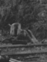 Hand-Levers. The original pair of hand-levers for points A1 and A2
were part of an 1877 order for such items to be supplied to the L&BR (click here for more details) and therefore may be presumed to be of the same pattern as
those used in the yard at
Pilton. The image shown here is an
extract from a larger photograph of the station taken circa-1935 and shows a
hand-lever of a different pattern on the outside of the loop line at the
approximate location of the toe of point G.
However a close examination of the larger source image suggests that this lever in fact
is working point A2 and that the lever for point G
was out-of-sight to the right with only the connecting rod to the point being
visible. It is not clear therefore whether the lever in the image was supplied
for point G, but somehow became swopped with the one at point
A2, or whether it was an early replacement (for some unknown
reason) of the A2 lever, in which the case the source and
pattern of the lever for point G remains unidentified.
Hand-Levers. The original pair of hand-levers for points A1 and A2
were part of an 1877 order for such items to be supplied to the L&BR (click here for more details) and therefore may be presumed to be of the same pattern as
those used in the yard at
Pilton. The image shown here is an
extract from a larger photograph of the station taken circa-1935 and shows a
hand-lever of a different pattern on the outside of the loop line at the
approximate location of the toe of point G.
However a close examination of the larger source image suggests that this lever in fact
is working point A2 and that the lever for point G
was out-of-sight to the right with only the connecting rod to the point being
visible. It is not clear therefore whether the lever in the image was supplied
for point G, but somehow became swopped with the one at point
A2, or whether it was an early replacement (for some unknown
reason) of the A2 lever, in which the case the source and
pattern of the lever for point G remains unidentified.
After these changes the general track layout remained unaltered for the rest of the life of the station, although there were further changes to the signalling installation during the subsequent period of Southern Railway ownership.
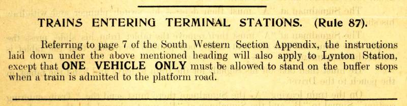
During the period of Southern Railway ownership from 1923 onwards some further changes were made to the signalling installation at Lynton. On 2-December-1924 (SR Signal Instruction No 25 of 1924) all the existing signals were replaced by 2 separate two-doll brackets, one acting as the Down Homes (DMH and DBH on the diagram below) and another situated on the platform as the Up Startings (UMS and UBS). (Click here to see the relevant extract from the Signal Instruction.) These bracket signals were of wooden construction to a former London and South Western Railway (L&SWR) design; some commentators have suggested that they were second-hand from replacement work elsewhere on the ex-L&SWR system, but it considered more likely that they were a new construction by a SR signal engineering department still working to 'traditional' ex-L&SWR designs. According to that Signal Instruction the Bay platform was designated as 'No 1 Road' and the Main platform as 'No 2 Road', which would equate with the SR practice of numbering the platforms at terminal stations from left to right as viewed from the buffer-stops end.
Southern Railway signalling at Lynton circa-1930
At some stage the 'economic' Facing Point Locks were replaced by the more usual 'independant' type which were operated by a separate lever from their respective point lever, and these are marked on the diagram as F1 and F2. (It is possible that point C may have been so fitted at a much earlier date, when it was introduced in place of the double-slip, but there would have been no need to alter point B1 at that time.) Photographic evidence of the rodding indicates that both the FPLs were worked from the same lever. It is quite likely that all the point rodding at Lynton was renewed as part of this work (including the alterations to the rodding to point B2 mentioned above), as there were many differences in later SR years from the pre-1923 equipment.
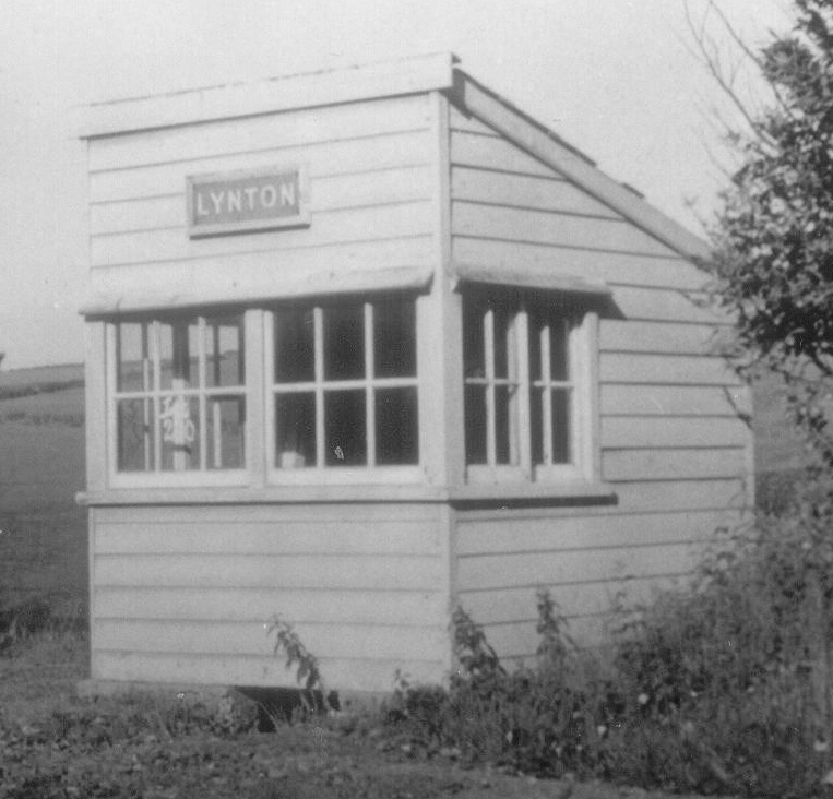
The L&BR-pattern SB hut was replaced by a L&SWR/SR-type pent-roof hut at the same location and fitted with a 'LYNTON' nameboard on the front wall above the window, as seen in this photo of the hut after closure of the line. This hut was listed as measuring 9'x8'x7'6" (average) in the Sale Catalogue after the railway closed in 1935. It is possible that the SR replaced the lever-frame as well, but it is known to have remained as 7 levers as it was listed as such in the Sale Catalogue. Assuming that the revised installation did not include any 'economy' measures such as push-pull levers and/or 'selection' of signals, then with 4 signals, 2 sets of points and 1 lever working both FPLs all 7 levers of the frame would have been in use.
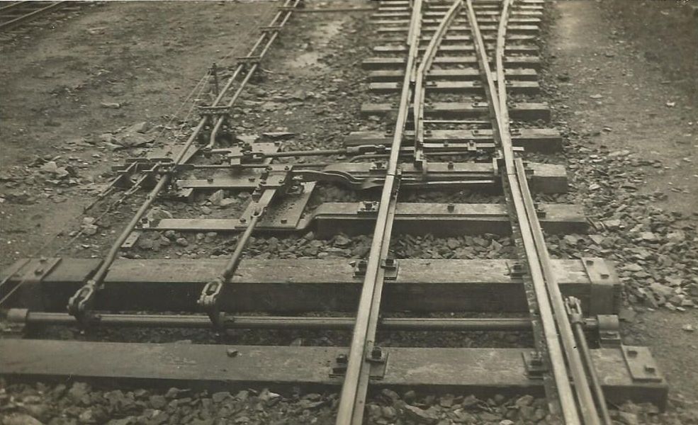
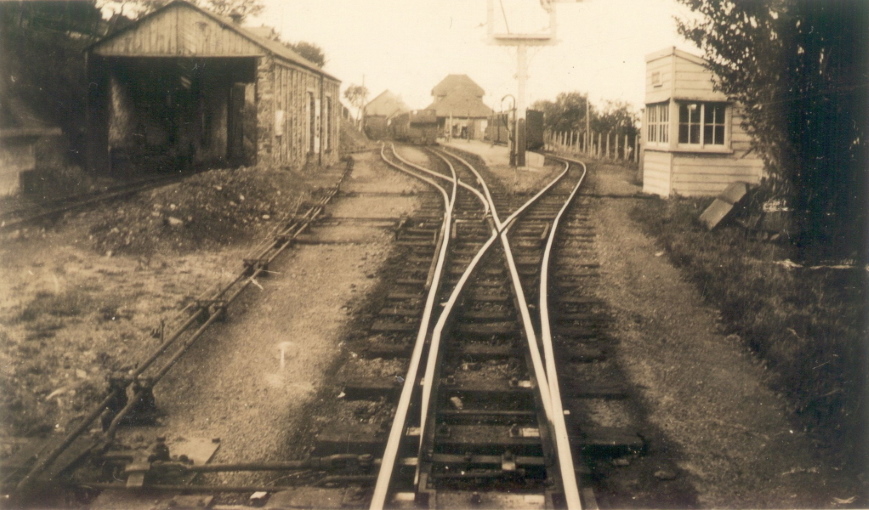
Two of the photographs shown below give a good illustration of the re-arranged pointwork, FPLs and rodding at the Woody Bay end of the station in the SR period. The left-hand image is known to have been taken in 1924; the middle image is undated, but is very similar to another known to have been taken in 1924 (not yet available on RailWest) and also showing the replacement bracket signals and SB hut. It is probable therefore (but not known for certain) that all the alterations took place at about the same time in 1924 as part of a general SR refurbishment programme. Thereafter the arrangement depicted in the circa-1930 diagram above remained in use until closure of the railway in 1935.
 |
 |
 |
The middle image above is a general view of the station 'throat' looking towards the actual station and shows most of point C (leading into the Bay platform) in the foreground with point B1 (leading into the Loop) beyond it. The left-hand image shows more detail of the 'toe' end of point C (out-of-sight in the foreground in the middle image) including the FPL mechanism and signal detector. Three rods emerged from the front of the SB and passed under the Bay platform line and point B1 to the wide cess on the Down side of the line. All three rods then turned left (southwards) towards the camera, but the middle rod bifurcated and also ran to the right (northwards) away from the camera; the portion coming southwards worked point B1 and the portion going northwards turned left under the engine shed siding to reach point B2. Once the set of three rods had reached the toe of point B1 the middle rod ended, the other two rods then continuing southwards with a gap between them; the rod nearer to the main line worked point C, whilst the rod further from the main line worked FPLs F1 and F2. The locking bar for FPL F2 can be seen on the outside of the right-hand rail in the left-hand photograph, whereas in the middle photograph the locking bar for FPL F1 can be seen on the outside of the left-hand rail.
The left-hand image gives a good view of the FPL and signal detector mechanisms associated with point C. On the far left can be seen the signal detector, this example having two signal slides parallel to the track, one for the wire to the Down Main Home (arm DMH) and the other for the wire to the Down Bay Home (DBH). At right-angles to those slides there is a single point slide, which is linked by rodding to a stretcher bar which connects the point's two switch-blades, but there is no slide to detect whether or not the FPL bolt is 'in'. The same stretcher bar is connected also to the point rod nearer to the track and forms part of the mechanism to move the point from one position to the other when the relevant lever in the SB is operated. There was a similar arrangement at point B1, except that its detector had only one signal slide as that point was in the route of the DMH only.
The transverse horizontal rod in the foreground between the two long point timbers forms part of the drive mechanism for FPL F2. Whenever the FPL lever in the SB is pulled or pushed the left-hand crank rotates the transverse rod on its axis and the right-hand crank causes the locking bar outside of the right-hand rail to rise and then fall again, thereby ensuring that F2 can not be operated if there is a train standing immediately in rear of the point. The middle crank is connected to the actual FPL lock plunger, which passes horizonally through slots in the two slide-bars which are attached separately to the two switch-blades. When the transverse rod is rotated towards the camera the FPL plunger is withdrawn, allowing the point to be moved; when the rod is rotated back away from the camera the plunger relocks the switch-blades. There were two slots in the slide-bars, side by side, as the point had to be locked for passenger train movements over both routes. A similar arrangement existed at point B1, except that its transverse rod was shorter as the locking bar - and hence the right-hand crank - was on the outside of the left-hand rail. Given that there were no passenger train movements on the route into the Loop it is possible that FPL F1 was not locked when the point was reversed and therefore there was only one slot in each slide-bar (for the route towards the Main platform), but the photographic coverage is not clear enough to clarify the issue.
© CJL Osment 2003-25
Acknowledgements to Michael Bishop and the Signalling Record Society
for archive information. OS map extract reproduced with permission of the National Library of Scotland,
trackwork photographs from L&BR Trust Archives courtesy Keith Vingoe,
all other images WCRA collection.
| Interested in the Lynton
& Barnstaple Railway? Then why not join the Lynton & Barnstaple Railway Trust and help to re-build England's premier narrow-gauge line? |
| Introduction | Original Layout | Revised Layout | SR Period | 1898 Diagram | 1910 Diagram | 1930 Diagram |
| © West Country Railway Archives 2003 Page last updated: 06 August 2025 |
URL:
E-Mail: |
||||||


