|
Home
The Railway Organisation
Plant Maintenance
|
Electrical Feeder Stations
A site visit to Kirkstall feeder station was undertaken; the main objective to look at the protection relays and to meet some engineers from Alstom. The Alstom engineers were trying to convince Railtrack to invest in some new protection relays.
Protection Relays Protection relays monitor the current and the voltage, measured by the current and voltage transformers. Knowing these values, the relay can then calculate the impedance between the OHL and the track. Impedance is similar to resistance, except that it only applies to AC electricity. Impedance, measured in Ohms, is known by the letter z, and is calculated in the following way: Impedance = voltage / current
On the OHL network, the value of impedance is relatively high. The voltage is approximately 25 000V and the current is approximately 600 A. Therefore the impedance is approximately 42 Ohms. If the value of impedance were to drop by an amount, outside of a set tolerance, the protection relay would initiate the contact breakers into opening, and therefore cut off the supply. Reasons for the impedance dropping can vary. These can be:
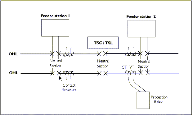
Neutral Sections These are in place to separate the voltage between two feeder stations. The simple following diagram emphasises this point.

The neutral sections are, as the term applies, void of electricity. If the pantograph of
an electric train were to stop under a neutral section, the train would not be able to
start again. This may seem like bad design, but this is the only way of keeping the different
electricity supplies apart.
The reason for keeping apart the electricity supplies is in case two different supplies are
in different phases. Each supply is single phase, but can be one of many phases. If two
different phased electricity supplies where to clash, big problems would be presented.

At the neutral section between the feeder stations, a Track Section Location (TSL) or a
Track Section Cabin (TSC) can be found.
Current and voltage transformers
These are in place to measure and transform the current and the voltage to the overhead line.
These are directly linked to the protection relays.
Circuit breakers
These ensure the flow of electricity to the OHL. Circuit breakers are basically large
switches and can cut off the flow of electricity to the OHL. Usually, all being well, the
breakers are in the position to make the circuit, that is, electricity will flow. Should the
protection relay detect a problem with the OHL, specifically, a drop in impedance, it will
operate the relevant breakers to cut off the power.
These circuit breakers can also be operated by the Electrical Control Operator (ECO) in the
case of possessions and emergency work.
These breakers can now be found indoors, but the initial trend was to place them on
structures.
Structure Mounted Outdoor Switchgear (SMOS)
SMOS is the equipment found at feeder stations, which is mounted onto masts or other
structures. For a while, this kind of equipment was considered to be the best, but engineers
are starting to realise that indoor switchgear is much more effective.

An overall simplified diagram of The OHL structure can be seen below:

Track Section Locations / Cabins (TSL / TSC)
A site visit to Leeds, Armley was also undertaken, to look at a TSL. This falls under
distribution, and the job of a TSL is to provide an electrical bypass. The Leeds area is
shown below.
A simplified version of the TSL is seen below.

A TSL and a TSC do exactly the same thing. The difference between them is that the
TSC is housed indoors whereas a TSL is not. If the power supply was to fail at a feeder
station, the electricity from the next feeder station along could be bypassed the neutral
section via the TSL and used to supply the next section.
| ||||||||||||