TrainWeb.org Facebook Page
Member Profile -- David Derway

This page has moved permanently. If you are not redirected automatically, follow the link to https://nrmrc.org/info/members/david-derway

Track Spacer

NRMRC Logo

Member Profile
David Derway

Photo of David Derway


Track Spacer

Table of Contents

Profile — David Derway

  Personal Profile

  Home Layout Profile

  Module Profiles

Modules Page

Roster Page

NRMRC Home

Click on title for desired topic.

Personal Profile — David Derway

by Jan Poff

David Derway was born in Burlington, Vermont, and spent his first eight years growing up in the north. He and his brother were introduced to model trains one Christmas by their father, John. A twin oval track layout installed on a piece of plywood ran 2 Lionel trains. The Rutland Railroad right of way passed through their property along the shore of Lake Champlain, and John would tell his sons many stories of what happened along the tracks when the Rutland was in operation. 1965 saw the family move south with the work transfer of their father with IBM to Raleigh, and ultimately the Research Triangle Park. The Lionel trains moved south as well, but didn't manage to get reassembled. After several years of no trains, David's brother, Allen, came home with the news that he had seen a neat new small train set at the local hobby store and if they pooled their allowance for awhile, they could purchase it. Within a few months, the Aurora Postage Stamp Train Set was

brought home with several additional pieces of track. The bedroom floor (thankfully a wood floor) became the impromptu setup area and months of fun ensued.

Soon High School and then College became the priority, and in 1981, he received his Bachelor of Science in Mechanical Engineering from North Carolina State University in Raleigh, N.C. Over the years, he worked as a Designer, a Design Engineer, a Project Engineer and then as a Product Engineer for various firms. He married his wife, Joanne, in 1985. She is, in fact, the reason he regained his interest in trains.

David's DG&N layout is a freelanced pike of the 60's to 90's era. Although he has been actively reading about model railroading for years, he just started work on his layout in late 1999. He has always enjoyed working with his hands and seeing the results of his work in whatever he attempts. Sometimes the results aren't exactly what were expected, but that is part of the fun.

Beside working on his DG&N layout, David and his wife enjoy camping and traveling in their motor home.

How I Ended Up in N-Scale
"It's my wife's fault!" I exclaimed after someone asked how I got back into N-scale. My first foray into N-scale began with the purchase of an Aurora Postage Stamp Train Set back in the early 70's. My brother and I paid for it out of our combined allowance, and it took months before we could bring it home. After playing with it for quite some time, it was dutifully put back up and carted around North Carolina for the next 17 years, seeing only occasional use. Within a few years of being married, my wife had had enough of my restlessness. You see, I liked to keep busy fixing things, building things, doing stuff with my hands. One winter, I had managed to fix the cars, fix the appliances in the unit we were renting, had built all of the stuff we needed, and now I was driving my wife nuts by constantly getting in her way.

Finally she said "Don't you have a train or something packed away that you can mess with and stay out of my hair?" The little light bulb went off over my head and I immediately went into the storage room and dug out the little Postage Stamp Train Set and original power pack. The dining room table was commandeered for a simple oval of track (the first hint for my wife that she may be in trouble), and within minutes, the 17 year old train was running around it. "Cool!" I said as I watched the engine and cars go around and around.

Later that evening, I wondered how much more there was to this train thing. Off to the local newsstand where I obtained my first issue of Model Railroader. "Holy Smokes!" I thought as I read every article several times and marveled at the photographs. My wife made me show her that I hadn't hidden a Playboy magazine in it after several hours of not hearing from me on the couch. Now all that little oval needed was some switches, some new cars, and maybe even a new locomotive or two. A quick look in the back of Model Railroader showed me the closest hobby shop — The Antique Barn & Train Shop (AB&TS) in Wilson. My wife and I planned a trip that weekend to go both train shopping and Barbeque eating in one journey.

When we arrived at the AB&TS, I took two steps into the door and stopped dead. "Ohmighod" was all that came out of my mouth. My wife gave me a shove in the back, and I stumbled toward the N-scale stuff. After looking for quite some time, I meandered over to the HO scale stuff and noticed how much more of it there was, both in selection and quantity. Uh-oh. A dilemma of monumental proportions was taking hold. Now what do I do? Do I stay with N-scale or go to HO? Realizing that a life changing decision would have to be made (at least that's how it seemed at the time), I decided to make the first purchase a small one. I picked up a couple of Atlas switches, some flextrack, and a couple of freight cars.

Upon getting home, I put the switches and flextrack into the oval (still on the table) and noticed how quickly the overall size increased. Hmmm. The more I read about the different scales, the more I realized that N-scale would allow me to get MORE railroad into a SMALLER area, and have MORE scenery than track. Hmmm. My eyesight was still pretty good so putting the cars and locomotive on the track wasn't a problem. Hmmm. My previous dealings with HO-scale had not shown it to be better … just bigger. Hmmmm. I figured that I could build a small N-scale layout that could be easily put up out of the way, while a small HO-scale layout would be much more difficult to maneuver. OK, decision made. Stick with N-scale.

It's a decision that I have not regretted, even if my eyesight isn't what it used to be. After all, isn't that why they have all those different magnifying products?

David is also the author of the article "N-Scale Atlas Shay DCC Installation" published in the May 2005 issue of Scale Rails, the magazine of the National Model Railroad Association.


Top


Modules Page


Roster Page


NRMRC Home


Track Spacer
Home Layout Profile
Adventures In Model Railroading

How My Railroad Came to Life
This was it. I had finally decided to get busy and build my DG&N Railroad. Somehow during the 15 years I had been dreaming about the freelance pike, it hadn't materialized out of thin air. The countless issues of Model Railroader, N Scale, and other publications too numerous to mention had been followed by hours and hours of perusing videos on how to build a model railroad. No doubt that I was read...or so I thought.
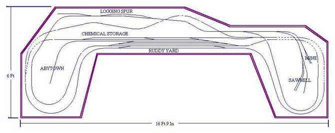
Step 1 — Track Plan
As an Engineer by trade, this part comes naturally. Engineers love to plan things to death before doing anything, so it only took around 7 years from my first scratchings to a real track plan. With a Christmas present from a sibling of RailCad several years ago, John Armstrong's Track Planning For Realistic Operation, and Lord knows how many published track plans and planning guides at my disposal, I'm surprised that I actually made up my mind at all. The final track plan was developed (at least the final one for now) and printed out on trusty 8 X 11 sheets. Unfortunately the layout is 6' X 17', so it took a LOT of paper and tape. Need I say that the latest track plan barely resembles my original scratchings?
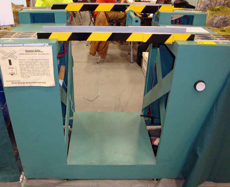
Step 2 — Benchwork
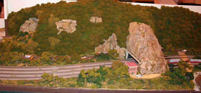
Now for something to put my hands on! Real wood, screws, glue, table saws, cut fingers, splinters..oops, I digress. It's surprising how heavy a 1" thick, 4' x 8' 11-ply sheet of plywood weighs. Mental note..get help on second trip to lumber store, I'm not as young (or as strong) as I used to be. Thank goodness the 2" foam board was easy to maneuver (at least until it got sideways in 20 MPH winds). But the payoff..Yea!, I'm actually building something! Thankfully RailCad had allowed me to draw up the benchwork while the track plan was underway, so again, I had a good drawing to go by (there's that Engineer thing again). To make a long story short, the benchwork was built in 3 sections as this was the only way to get it upstairs into the family room. After completion, I realized that it might be slightly overbuilt for N scale, as I could probably drive my car onto it without damage. I had learned one lesson though. A neighbor helped me move the sections upstairs, and I gladly gave him the six-pack of beer I promised.

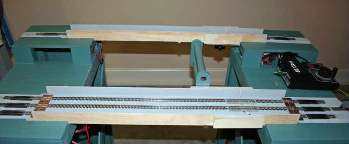
Step 3 — Tracklaying
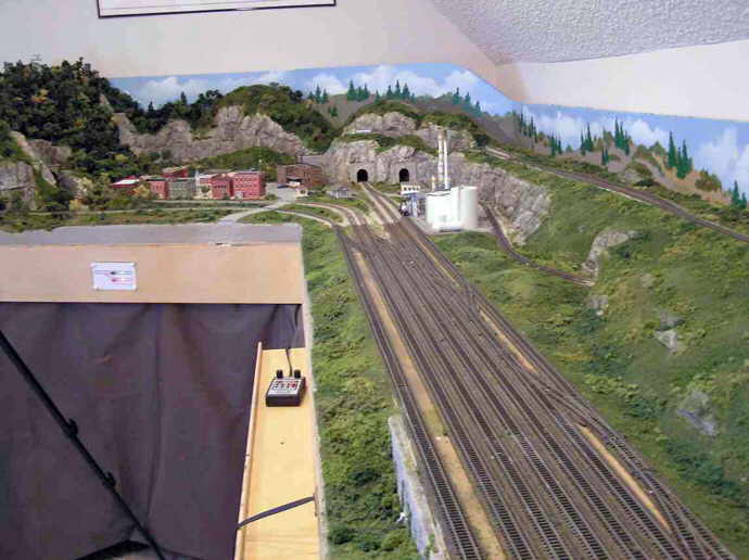
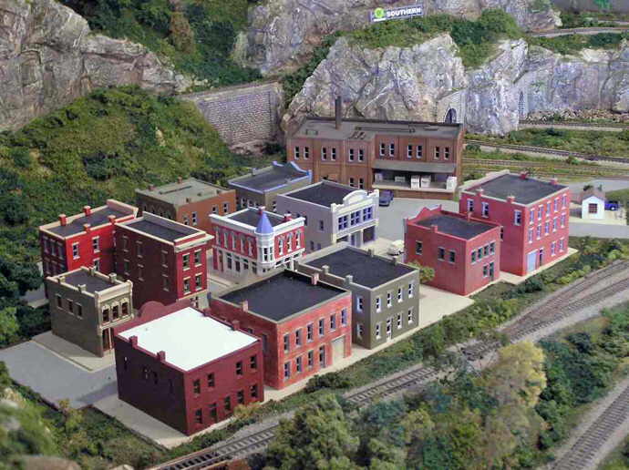
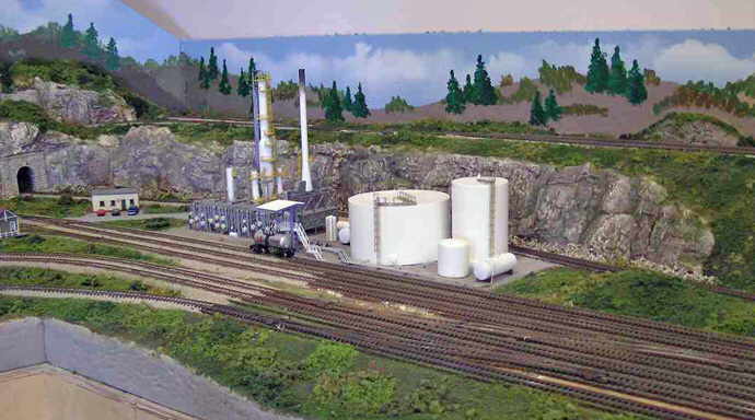
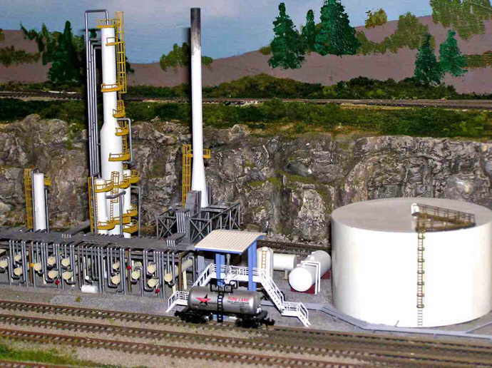
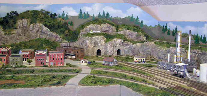
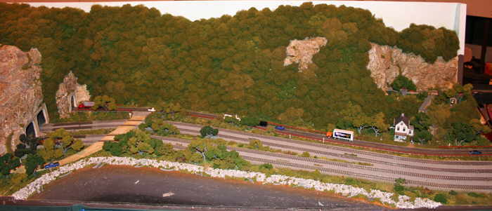
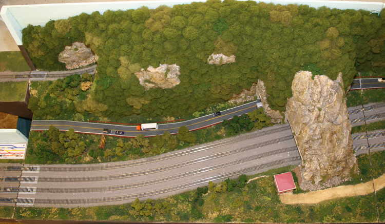
For track, I am using Peco Finescale code 55 track on 3/8" plywood splines on top of 2" foam. Don't ask me how in the world I came up with this combination. I must have seen it SOMEWHERE. Cork subroadbed was glued to the splines and the track was tacked to the cork with super glue. I keep a bottle of super glue debonder handy just in case. For me, not the track. This part was uneventful, except for the last minute change in the track plan (so carefully thought out years earlier) while the track was being put down. Lets see..take this out..add this..move this over. Since the layout has 2 areas (one town and one industrial) for switching interests that would interfere with building scenery in a couple of places, I decided to complete most of the tracklaying, wiring and start the scenery before laying track in those 2 areas.

Step 4 — Wiring
My plans are to go DCC, but I wanted to start simple, so after an exhaustive and unproductive search to find my old DC power pack, a new Tech II power pack was purchased. 20 AWG solid wires are used as feeders every 18" or so and are tied into a 14 AWG buss wire. Luckily for me I still had a spool of this wiring left over from wiring my garage. A total of 3 bus wires were run to different areas for overcurrent protection, but temporarily tied together. After reading Allen Gartner's web page on Wiring For DCC, I modified a tester I had to troubleshoot the wiring. This proved invaluable as wrapping the 20 AWG feeders onto the 14 AWG busses was a little difficult since I ran out of one wire color close to the end of the wiring job, and my enthusiasm for seeing a train actually running on the track was clouding my judgment. Lets see..did I run out of red, and then use green? Or did I run out of black and then use green? Drats.

Step 5 — Run Trains (Intermediary)
Once all of the wiring was debugged, it was time to hook up the power pack and watch those trains run! Well, at least that's what I thought as I watched the first loco lurch and wobble it's way down the track. Mental note 2..clean locomotives if it has been over 8 years since they have been run. Fortunately, once cleaned and properly lubricated, the little SW1200 glided down the track smooth as silk. Success! Although it was running on unballasted track on a sea of blue foam, it was running and running well. It had taken almost 8 months from the time I printed out the "final" track plan to make it this far, and I was pleased with the result. Time to take a break and enjoy running different trains before the next step, scenery.

But how long could I run trains before getting to the scenery? Quite a while, in fact. 3 months of digging out engines and cleaning them up, finding cars that run well, then building trains and watching them run seemed to fly by. OK, I must confess, this was the stage at which two previous attempts to build a layout on a smaller scale had succumbed to being another pile of lumber and partially laid track. But I was determined that this time, scenery was going to happen. The advice from many publications was to start scenery in one area, instead of trying to do the whole thing at one time. This turned out to be the best piece of advice I had read. First things first, I had to find any scenery materials that had been purchased over the years, determine if they were still usable, and then get to work.

Two weeks of digging through the storage areas under the eaves of my home brought forth quite a number of Woodland Scenics tree kits, turf, and the most curious collection of now worthless odds and ends. Off to the not-so-local hobby shop to pick up additional supplies to begin my layouts' transformation!

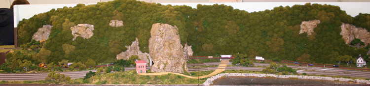
Step 6 — Basic Landforms and Plaster Cloth
Since the model magazines always showed this part in only a couple of pictures, it had to go fast, right? Not a chance. I ended up using a combination of carved foam scraps and malleable screen wire for the mountainous area, and ½" thick pink foamboard as the backdrop. On to putting the plaster cloth over the combination and creating real mountains. Of course, usually making a mess is fun, and this was no different. Mental Note....change into old clothes before slinging plaster! Thankfully I had covered the track with tape and the floor with plastic sheeting. The plaster cloths' packaging says "Covers 10 Square Feet". I have news for them, it doesn't. Another mental note — determine how much plaster cloth you need and DOUBLE IT! But at the end of 2 more weeks, I now had mountains . . . sort of, actually more like big bulges of white plaster. Lets see, how do I add the wonderful detail I've been reading about for years — of course, rock castings!

Step 7 — Rock Casting and Lightweight Hydrocal
Back to the hobby shop for some boxes of lightweight Hydrocal, a rock mold and more odds and ends. Since I don't plan in getting into trouble with my wife by using her measuring cups, and the instructions show a roughly one to one and a little bit ratio, I determine that mixing by eye and maybe being a little off wouldn't hurt. Wrong again. Most of the castings go real well, but with others, the mix sets up before I can pour it, and yet some take 2 days to solidify. Lesson learned. On my next trip to the hobby shop to get more Hydrocal (now on third box), I stop by a Family Dollar store and pick up two 4 cup plastic measuring cups. I also made some castings using an alternate plaster from Wal-Mart and some Sculptamold that I had on hand.

Now armed with many castings, I start the task of trial fitting them in place. Immediately I realize "How in the world can I keep them in order?" Simple solution, put a number or letter on the back of each casting and on the part of the mountain it goes on. Doing only 5 or 6 castings at a time, this goes very well for the first couple of days. Each casting is blended into the one next to it with additional Hydrocal. On day 3, I notice that the previous castings are taking on a pinkish hue. "What in the world?" Then I remember, I used a red marker for the letters, and since plaster is porous – DUH!

After letting my first now-complete and getting-redder rock face dry for several days, I decide its time to start the staining stage. Careful review of The Clinic Video from Woodland Scenics leads me to gain much needed confidence. The stains are mixed up and applied randomly to the rock face, immediately followed by a thin black wash. My hopes leap upward as the reddish hue disappears and is replaced by a good looking greyish tint. Earth colored stain is used on the top of the mountain area where grass will eventually be, and then matte medium is sprayed over the entire mountain to fix the stains. I let this sit for a week to see if the red would reappear, and luckily for me it did not. On to the next rock face.

This one went much better until I put the stain on. One big casting just wouldn't take the stain like the others and stood out like a sore thumb. Some of you have probably already guessed it – yep, it was a casting made out of the alternate plaster. This was my lesson that all plasters are not created equal. Add one day to separate all of the Wal-Mart plaster and Sculptamold castings to the schedule, one day to dig out and replace the carefully applied casting and yet another to stain the new casting to match the rest of the rock face.

By now I was noticing that those little 2 lb boxes of Hydrocal were disappearing at a rapid rate. After much discussion with the Budget Foreman, it was decided to make a bulk purchase of Hydrocal. Woodland Scenics promises 20 lbs in their bulk package, and they didn't disappoint. Soon 27 lbs of it appeared on my doorstep, along with quite a collection of grass, turf and clump foliage. It turns out that the Budget Foreman has a good eye for what looks right and what doesn't, and she in turn chose the colors and textures for the weeds and bushes. I am also wondering at this point if Woodland Scenics is on the stock market as I believe I am single-handedly keeping them in business!

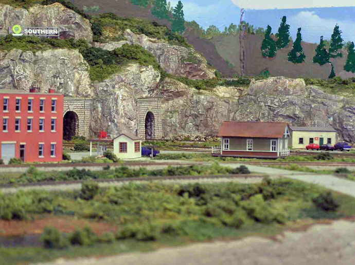
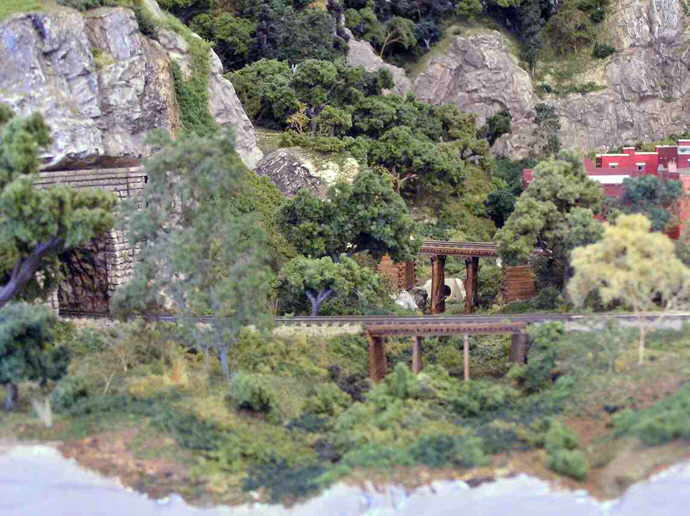
The weeks pass by as I make even more castings (with additional molds won in a now-you-have-it, now-you-don't gift exchange), set them around tunnel portals and make even more rock faces. I stand back and review my work so far. I'm again pleased with the results. It may not be Reid Brothers quality or John Allen's awe-inspiring scope, but for a beginner, it isn't bad. Time to pull up the tape, clean the tracks and run some more trains before putting down some foliage and trees. Anyone need some Hydrocal?

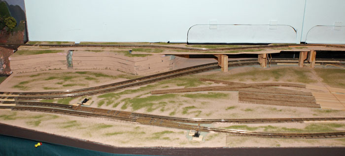
Step 8 — Earth and Foliage
My plan was to take up the non-stick masking tape, clean the track and run some trains, but I decided that while the track was protected, I might as well go ahead and try my hand at putting down dirt and some foliage. At least this is the reasoning I used to finish off the Woodland Scenics Landscaping Learning Kit I had purchased before. Then I'll do the track and find out if the locomotives will clear the tunnel portals and if I've missed any spots of track-covering plaster.

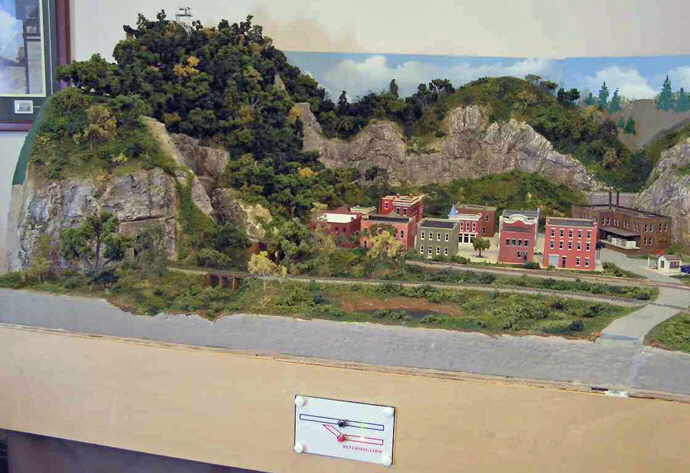
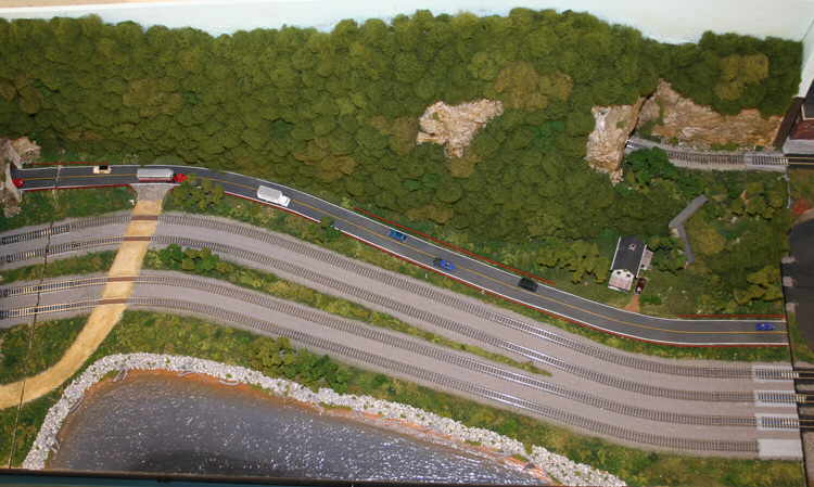
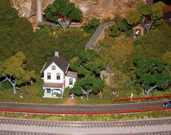
Following the instructions of the kit (to the amazement of the Budget Foreman), I mixed up the earth stain and covered the remaining white plaster areas. Fine soil turf was flyspecked onto the rock faces, and fine green blend turf was used to cover the area that had just been stained earth color. The turf was applied at different thicknesses to vary the color and grass effect. Then other color fine turf was applied in random areas. Next weeds (heavy turf) and finally bushes (clump foliage) were applied, paying attention to where they would normally be found in the landforms. The clump foliage was glued to the layout with Hob-e-Tac, a rubber type cement. A side note on this adhesive — whoever came up with this stuff is evil. The bottle says "Bonds on Contact" and they aren't kidding. Get some on your fingers, and every piece of clump foliage you try to place on the layout will find it's way to your fingers, and it won't let go! A layer of Scenic Cement was applied over the entire scenicked area, which was now about 2 feet by 3 feet. The cement was allowed to dry and minor touch ups were completed. The Budget Forman played an important part here by letting me know what looked "right" and what didn't. Now it's time to clean track and run some trains!

Step 9 —Track Cleaning
As I carefully pull up the non-stick tape, I notice little black lines arranged neatly on the underside of the tape. Uh-oh. It seems that the paint I used to carefully weather the track has an affinity for the non-stick tape. Well, it appears that I will have a chance to hone my airbrushing skills once more. This is also the time that I notice some of the tape is buried under 1/8" of plaster in some areas (of course only visible from certain angles that weren't used when applying the plaster). Another mental note – find out where all that plaster is going before adding more! A Bright Boy cleaning block and emery paper was used to clean off the rail tops and to clean up the turnout points. Dental tools were used to clean plaster from between the ties and to reform the ditches that were accidentally filled with plaster during mountain making. Careful vacuuming removed the errant plaster chips and other debris. Oopppps! Was that some weeds and shrubs that just disappeared into the vacuum cleaner?

Step 10 — Run Trains
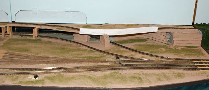
The good 'ol DC power pack was hooked up and several days of running trains took place. Although the portals located on curves are a tight squeeze, everything clears. I can see how this could be a problem for folks running big diesels or articulated steam locomotives, however.

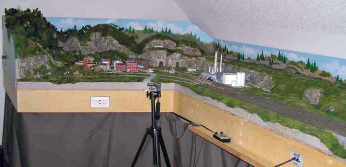
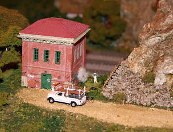
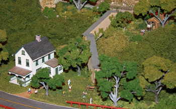
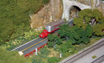
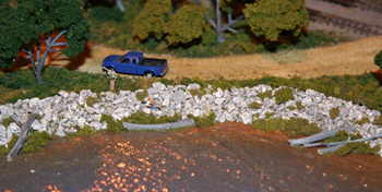
After running trains, I repeated the above steps 2 more times (with lessons learned) to expand the scenicked areas and rock faces to approximately 18 square feet total, about 1/3 of the layout. It is hard to explain the feeling of accomplishment I felt as I watched the trains go through the newly scenicked areas. Although I was originally worried about how it would turn out, I finally took the plunge to try scenery, and it has really paid off. Hey, if I can do it, anybody can!


Track Plan

Derway Home Track Plan


Photographs

Derway Layout 1
Derway Layout 2
Derway Layout 3
Derway Layout 4
Derway Layout 5
Derway Layout 6
Derway Layout 7
Derway Layout 8
Derway Layout 9


Top


Modules Page


Roster Page


NRMRC Home


Track Spacer
NTRAK Module Profile

Breakneck Mountain, NY


Geezer Gate


Rockin' Toxin


Legend

All descriptions refer to looking at the front of the module.
CCW = Counter-clockwise; CW = Clockwise
Crossovers indicate travel from left to right.
Div, Divn = Division
Mountain Division = Green Track
Mtn = Mountain


Module: Breakneck Mountain, NY

Owner Name:

David Derway

Builder Name:

David Derway & David McDowell

Date Built:

2001 – 2006

Status:

Complete

Module Type:

Standard 8' module with Orange Track and Mountain Division

Length:

8' (2 x 4')

Width:

2' + Mtn Divn extends 3" from skyboard rear

Passing Sidings:

None

Other Tracks:

Orange + Mountain Division

Industrial Spurs:

None

Yard Tracks:

None

Engine Service:

None

Crossovers:

None

Electrical:

Track Buses:

12-Gauge Wire with Powerpole Connectors

12VDC Bus (White):

12-Gauge Wire with Powerpole Connectors

Accessory Bus (Brown):

Not installed

LocoNet Bus:

Installed

Module Photograph

Breakneck Mountain Left Front

Breakneck Mountain Right Front
Breakneck Mountain, NY (Top photo = Left half of module; Lower photo = Right half)

Breakneck Mountain Full Front
Breakneck Mountain, NY (Full view)

Track Plan

Breakneck Mountain Track Plan Left

Breakneck Mountain Track Plan Right
Breakneck Mountain, NY (Top photo = Left half of module; Bottom photo = Right half)

Description
Breakneck Mountain is a freelanced interpretation of the upstate area of New York and is loosely based on the module pair built by Dick Christianson and featured in Model Railroader Magazine, April and May issues of 1988. The module frames, initial wiring, track work and extruded form landscape base was built by David McDowell with help from several club members. David donated the pink foam covered modules to NRMRC, and were subsequently adopted by David Derway. David added the mountain division and brought Breakneck to the current level of completion, including rewiring with new 12-gauge bus wires and Powerpole connectors. The farm house was built by Jan Poff and the pump house was built with DPM modular sections by David Derway.

Additional Photographs

Breakneck Mountain 01  Breakneck Mountain 03

Breakneck Mountain 02   Breakneck Mountain 04

Breakneck Mountain 05


Top


Modules Page


Roster Page


NRMRC Home


Module: Geezer Gate

Owner Name:

David Derway

Builder Name:

David Derway

Date Built:

2007

Status:

Final Construction/Finishing

Module Type:

Special 4' module with Lift Bridge and Mountain Division

Length:

4'

Width:

2'

Passing Sidings:

None

Other Tracks:

Mountain Division

Industrial Spurs:

None

Yard Tracks:

None

Engine Service:

None

Crossovers:

None

Electrical:

Track Buses:

12-Gauge Wire with Powerpole Connectors

12VDC Bus (White):

Not installed

Accessory Bus (Brown):

Not installed

LocoNet Bus:

Not installed

Special:

Geezer Gate should be the LAST module to be clamped into the layout. Adjacent modules should be level to each other before putting Geezer Gate in place.

Geezer Gate must be unclamped before any module line up it is part of is racked.

Module Photograph

Geezer Gate Front

Track Plan

Geezer Gate Track Plan

Description
Geezer Gate provides an easier means of ingress/egress to the inner portion of NTRAK layouts by means of a lift bridge, which raises the NTRAK main and mountain tracks to allow a person to pass through module. The features of Geezer Gate are the following:

  • Counterweighted to hold bridges in open position.
  • Both bridges lift and lower simultaneously by a single handle.
  • Adjustable bridge length to accommodate humidity and temperature changes.
  • Electromagnet lockdowns for secure holding and horizontal alignment.
  • Alignment pins for precise vertical bridge alignment.
  • Bridge track rail ends soldered to PC board for alignment and maintaining track gauge. Also staggered and tapered so track gaps are not aligned.
  • Gaurdrails placed to trap wheels along rail, keeping other rail from jumping opposite gap.
  • Big push buttons for ease of operation when releasing electromagnets.
  • Electrical relay circuit shuts down power to entire module when either button is pushed and/or bridge is in up position. Buttons are momentary only.
  • Adjacent modules can be added to the stopped blocks with the addition of track bus extension cables.
  • Interior adjustable feet for strength and height adjustment.

The design of this module is based on an article titled "Build a Walk-Through Bridge" by Wayne Roderick, published in the August 2005 issue of Model Railroader.

Operating Instructions
The following operating rules are intended to permit safe operation of the bridge without disrupting train operations:

Basic Operation: Push the button to release the bridges. Lift the handle straight up till the bridges are vertical (or leaning slightly backwards from the closing side), walk through. The pushbutton may be released as soon as the bridges are about 1" above their closed position. Immediately turn around, and use the handle (top or bottom rung) to gently lower the bridges straight down to their closed position.

IMPORTANT ITEMS TO REMEMBER AT ALL TIMES!!!!!!!!!!!!

  • YOU are responsible for making sure a train is not on or entering the module when you push the button and lift that handle!

  • USE THE HANDLE !!! DO NOT lift or lower the bridges by the bridges themselves! Lift straight up and lower straight down.

  • Make sure the bridges are vertical (or leaning slightly backwards from the closing side) and are held by the counterweight before turning the bridge handle loose. DO NOT let the bridges slam down!

  • Once through the geezer gate, make sure you CLOSE the bridges (by the handle) immediately! DO NOT let the bridges slam down!

  • NEVER force the handle open or slam it shut. If the magnets haven't released when you push the button, or the alignment pins have locked the gate closed or they won't allow the bridges to close, use another means to get inside or outside of the layout and contact David Derway, the owner of the geezer gate immediately.

  • Did we mention…ALWAYS USE THE HANDLE?!?!?!

Additional detailed information: This module is a lift-bridge design, with electrical interlocking to remove power from switched rails when the bridges are open. The electrical interlocking is accomplished through a relay and electromagnet circuit. The circuit operates as follows:

  • During normal operation, power is provided to the switched tracks through the relays. The relays get this power directly from splices off the 12AWG Main Through Power Bus.

  • The power to close the relay circuit is provided by a 800MA 12VDC wallwart, routed through a pair of momentary hand operated push button switches, and through bridge location switches for each bridge. This power circuit also provides power to the bridge hold down electromagnets.

  • To operate the bridge, push one of the large momentary switches. This opens the relay/electromagnet circuit, cutting power to the electromagnet (which releases the bridges), and causes the relay to switch to the normally closed position, cutting power to the switched tracks.

  • The bridges are raised via the handle, which open the bridge location switches, and the push button switches may be released. The open bridge location switches maintain the open circuit, which keeps power to the electromagnets and relays off.

  • Once ingress/egress has been completed, the bridges are lowered via the handle to their closed positions. The lockdown circuit will be activated once the bridges have centered on their respective centering pins and have traveled far enough to close the bridge location switches. This will pull the mating plate firmly against the electromagnet and also restores power to the switched tracks.


Top


Modules Page


Roster Page


NRMRC Home


Module: Rockin' Toxin

Under Construction

Owner Name:

David Derway

Builder Name:

David Derway

Date Built:

2009

Status:

Under Construction

Module Type:

8' Module (2 x 4') with major Industrial area

Length:

4'

Width:

2'-6"'

Passing Sidings:


Other Tracks:

Mountain Division, Orange

Industrial Spurs:


Yard Tracks:


Engine Service:

None

Crossovers:

Red-to-Orange; Orange-to-Red

Electrical:

Track Buses:

12-Gauge Wire with Powerpole Connectors

12VDC Bus (White):

12-Gauge Wire with Powerpole Connectors

Accessory Bus (Brown):

12-Gauge Wire with Powerpole Connectors

LocoNet Bus:

Installed

Special:


Module Photograph

Rockin' Toxin Front Left
Rockin' Toxin Left Side

Rockin' Toxin Front Right
Rockin' Toxin Right Side

Track Plan

Description


Top


Modules Page


Roster Page


NRMRC Home


Track Spacer

Copyright © 2006–2010 North Raleigh Model Railroad Club. All rights reserved.
The NRMRC is a Not-For-Profit Corporation incorporated in North Carolina.
The various logos and heralds shown here are the property of their respective organizations.

Last updated: Tuesday March 9, 2010


North Raleigh Model Railroad Club
Webmaster: John M Wallis (Email)