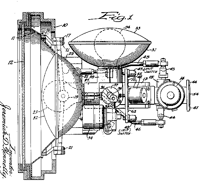


Figure 1 is a plan or top view of the light unit.
Figure 2 is a side view.
Figure 3 is the lamp support.
This light unit uses 2 lights: one white for regular operation and the other red to indicate danger. A subframe 16 carries 2 light sources 23 and 24. The sockets 27 and 28 of these lamps carry reflectors 29 and 31 which can be closed by glazed covers 32 and 33.
Support 25 is turned by motor 34. This in effect, turns one of the desired lamps into the operable position as a warning light, while at the same time rotating the other lamp out of way. Limiting switches stop the motor 34 when the desired position is reached.
Oscillatory motion of subframe 16 is accomplished by motor 14,
through gear box 15, through cranks 43 and 44, through links
45 and 46, to rings 17 and 18.
Link 45 rocks ring 17 about it's vertical pivots, while
link 46 will rock the ring 18 about it's horizontal pivots on ring
17.
By properly relating speeds of the links 45 and 46
and angular displacement, any desired pattern could be obtained.
Cranks 43 and 44 may be driven at different speeds to obtain
patterns such as the "FIGURE 8".