Beam spread (or Beamwidth):
I've usually seen beamwidth described as the boundary at which the light intensity is 50% that of the intensity at the center, or most intense portion.
Dave VanHorn
We use a Tektronix J16 Digital
Photometer with a remote probe.
Mount the probe on the wall of the darkroom.
Mount the light on a 2-axis swivel (calibrated in degrees) and move it through
various angles measuring the light output at each point.
Half-power points are the beam width. Unless the customer specifies a
particular pattern.
�Roy Gordon - LUMINATOR, Plano, TX
GE has confirmed that this is also the way that
beam spread is defined. It is the conical section at which the light intensity
falls to 50% of the maximum brightness.
The following isocandela information is taken from the Final Report (July 1995) of the US Department of Transportation and the Federal Railroad Administration entitled: Safety of Highway-Railroad Grade Crossings - Use of Auxiliary External Alerting Devices to Improve Locomotive Conspicuity DOT/FRA/ORD-95/13 DOT-VNTSC-FRA-95-10
Appendix C of the above referenced report shows 2 independent isocandela diagrams of the GE 200PAR bulb (200W 30V PAR-56):
1) The USCG results show a max. candela of the bulb of 265,000 @ 30V. The beam spread is stated to be 5� in the vertical direction and 5� in the horizontal direction.
2) The Quest Corporation (North Royalton, OH) submitted data show a max. candela of 217,500 @ 30V. The beam spread looks (from isocandela diagrams) like it is in the vicinity of 4.5� in both vertical and horizontal directions. The Quest Corporation states that isocandela diagrams which they submitted for the above report were from the bulb manufacturers, which, in this case was GE. The Electrical Aspects page also has information on this.
I consistently measured and calculated a value of 4.6� (both vert. and horz. directions) for 2 GE bulbs. These were used bulbs. The max. candela I measured at 27V was 193,000 (using a light meter with 5% accuracy which read in foot-candles). The candela was computed by multiplying foot-candle reading by the distance squared - from light source to light meter probe).
The GE PAR-56 200 watt, 30 volt locomotive sealed beam bulbs are documented as having a beam spread of 9� (both vert. and horz. directions).
I contacted OSRAM SYLVANIA and asked them if the stated value of the 200W 30V PAR-56 bulbs that they sell were accurately documented as the 4� beam spread (both vert. and horz. directions) @ 50% max. candela. I asked if the value was accurate to a tenth of a degree - and they affirmed it was.
The isocandela diagrams do not show perfect circle contours due to the manufacturing process. The theoretical perfect parabolic reflector with the filament at the exact focal point (and existing as a point) is not realized. Any manufacturing bias will have and effect on the contour configurations in the isocandela diagrams. There is apparently an averaging that takes place in arriving at published values.
In view of the confusion of the GE information, I have used OSRAM SYLVANIA's beam spread of 4� in the following diagrams.
In the following beam patterns, the centerlines of the beam are illustrated. One would have to construct a parallel curved line to this centerline, 2� on each side, to depict the observed beam coverage.
The beam patterns were arrived at using the
following procedure:
Keychain laser
pointers were used. The watch batteries did not have the capacity, so a 3 AA
supply was used. Holes to accommodate each pointer were drilled in 7"
plywood strips. These strips were centered in each of the headlight openings
using inner tube strips to hold them secure against the bulb plate. (The strips
for the Mars light units would have to be cut to accommodate the characteristic
lamp mounts which use the spring bars.) Each pointer was centered. A paper to
accommodate the pattern was taped to the ceiling. The 20585 Gyralites were
removed from the cases. They were leveled up on the floor, using shims where
necessary. The 17570 unit is built into it's case. The Mars 200 light was
tested with the cover removed.
Using a plumb-bob,
the points to the middle of the universal bearing, as well as the points to
determine the axis of the mechanism were marked on the ceiling mounted paper.
The points of the 2 pointers in the "straight-ahead" (parallel the
floor) position were also marked. (The sideways pivot points were used for
reference in the Mars 200 Light.)
Power was applied to the motor as well as the pointers. The pattern was traced out on the paper.
The distance attributed to the inclination of the universal bearing was measured (d1).The distance from the center of the universal bearing to its plumbed point on the paper was measured (d2).
Using the Tangent Inverse Function:
Beam Spread Angle for the sweep attributed to the inclination of the universal
bearing =
arctan(d1�d2) x 2
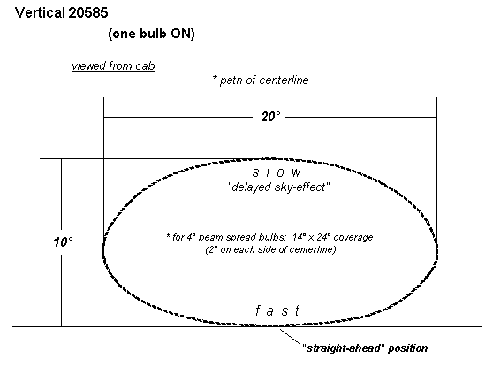
This value consistently proved to be 10�.
The Beam Spread Angle in the other perpendicular direction was obtained by measuring the perpendicular distance on the projected pattern and using the proportionate value (d1, 10�) to determine the degree value in this direction. The pattern on the paper was redrawn (see below).
In the following Right and Left will be taken to mean the side of locomotive for a mounted unit.
The convention of beam sweep is clockwise as viewed from the cab of the locomotive.
The 20585 Gyralite is available in 2 mechanisms.

The following illustration from US Pat. 2,677,121 illustrates measurements taken on the unit as configured as a Vertical 20585 Gyralite. The Horizontal 20585 Gyralite uses an offset pulley and the slide mechanism is 5.9" from the center of this offset pulley.

The beam pattern for the Vertical 20585 Gyralites with one bulb illuminated is shown below. Both sides of the pattern are symmetrical. The top of the ellipse shows increased curvature, whereas the bottom is flat. The rate of sweep is slow on the top and fast on the bottom. The slow sweep rate at the top is responsible for the phenomenon mentioned in the patent as the "delayed-sky effect".

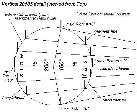
The length of the slide assembly which is
attached to the pulley is a constant so the illustration of angular settings
are shown at the intersection of the circular path of the slide attachment with
the centerline of the slide assembly. 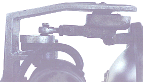
In the case of the Vertical 20585, the distance from the center of the circular
path (center of pulley) to the slide bearing bolt is 4-1/8". The closeness
of the slide bearing bolt to the circular path determines the size of the
differential on one side of the path and the other.
The part of the circular path near the slide bearing bolt is the fastest and shortest interval. For going from one angle to the next, notice that the interval on the side of the path nearest the slide bearing is small and the one on the side farthest from said bearing is large. Therefore, the part of the circular path farthest from the slide bearing bolt is the slowest and longest interval. This part is responsible for pulling the bulb plate upward, towards the sky. For the Vertical 20585, this means a slow "spectacular sky effect" and a fast traversing along the ground. (The centerline of the beam is parallel to the track. However, there is a 2� downward directed beam from the 4� sealed beam bulbs.)
The lines labeled gradient lines are drawn perpendicular to the axis centerline of the movement. These lines represent the up and down positions of the bulb plate for the various centerline angles of the slide assembly. In this case, the center of the pulley, the slide bearing bolt, and the centerline of the bulbs lie in a single plane.
One should notice that the gradient lines are symmetrical on each side of the axis centerline. In going from gradient line to gradient line on the side nearest the slide bearing, the difference is small - which results in a LINEAR bottom sweep. The differences on the opposite or far side of the circular path are large - which results in a CURVING top sweep.
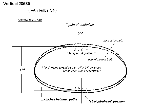
The Vertical 20585 Gyralite with both bulbs on is a reinforced pattern. The 2 bulbs are 8.5 inches center-center. The projected pattern results in two patterns, one above the other, with a distance of 8.5 inches between. An increased distance to this unit would make these bulbs appear as one bright source.
The Horizontal 20585 Gyralite pattern is shown below. The pulley is offset to the side so as to rotate the horizontal sweep of the Vertical 20585 to make the bottom of the pattern equal to the "straight-ahead" position. The rate of sweep is slow on the right and fast on the left (viewed from cab).
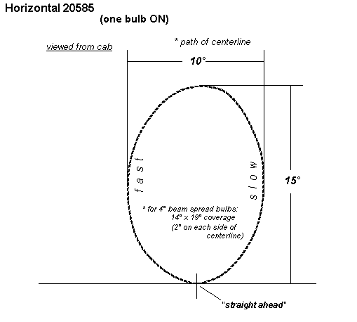
The length of the slide assembly is again taken as a constant. In this case the perpendicular distance is 5.9". The pulley in the Horiz. 20585 is displaced away from the axis centerline of the Vertical 20585 by 0.7". (away from case hinges). What this does is create a new axis centerline. The up and down swing of the Vertical 20585 was controlled by the back and forth rocking of the bulb plate via the universal bearing and the sideways beam was controlled by the pivoting via the slide bearing. The Horiz. 20585, and 17570 (or 17550) reverses this.
The pulley was displaced by the circular path's radius in order to have the bottom of the beam pattern's centerline correspond with the "straight-ahead" position of the locomotive. The gradient lines are not that symmetrical on each side. The 5.9" slide assembly causes the intervals between angles to differ less. There is a less drastic shape in going from the slow CURVING right sweep to the less LINEAR left sweep.
The switching of the axis causes maximum upward sweep to not occur at 180�, but 14� off this point.

The Horizontal 20585 Gyralite with both bulbs on is a reinforced pattern. The 2 bulbs are 8.5 inches center-center. The projected pattern results in two patterns, one on side the other, with a distance of 8.5 inches between. An increased distance to this unit would make these bulbs appear as one bright source.
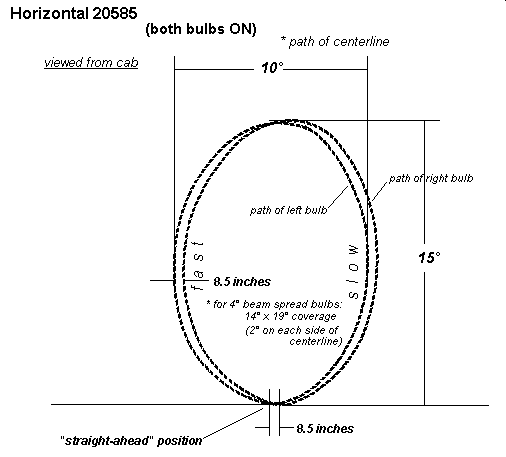
In both the Vertical and Horizontal 20585 Gyralites, the actual pivot point (center of universal bearing) of the bulb plate is not equidistant between the bulbs, but is closer to the lower bulb in a Vertical (or right bulb in Horizontal). This amounts to 0.5".
The 17570 Gyralite has the slide assembly also offset in order to make the bottom of the projected beam pattern equal to the straight-ahead, parallel to the track position. In this light, the centerline of the bulb is offset from its point of attachment to the slide mechanism by 0.7 inches. This contributes to the tilt observed in the pattern. Also the rate of sweep is fast on the right and slow on the left (viewed from cab). This is due to the slide being on the left side of the light, whereas in the Horizontal 20585 Gyralite, it is on the right (viewed from cab).

The length of the slide assembly is again taken
as a constant. Again, the perpendicular distance is 5.9" and the crank
block is displaced from the axis centerline of the Vertical 20585 by 0.7".
Whereas the slide bearing bolt was on the right side of a Horiz. 20585, it is
located on the left in the 17570. Instead of the pulley being displaced (as in
the Horiz. 20585) the slide bearing bolt is. It is displaced towards the top of
the mounted unit by 0.7". 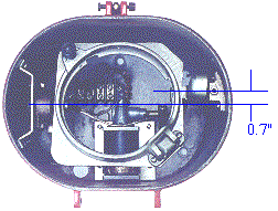 This would
create a diagonal sweep of the beam, so the centerline of the bulb plate was
offset back by 0.7". This means that the bulb plate's attachment to the
slide assembly is 0.7" from the plane of the universal bearing and the
center of the bulb. This 0.7� correction results in a tilted elliptical pattern
with a bias to the Right (as viewed from the cab).
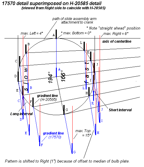
In the H-20585, the left and right extremes of the pattern were 5� on each side of the lowest, or "straight-ahead" position. The 17570 has the pattern shifted to the right by 1�, resulting in the left extreme of the path being 4� and the right being 6�.
The gradient lines for the 17570 are projected to those of the H-20585 to illustrate the tilting effect that the offset slide attachment has. The slow portion of the beam pattern is on the left in this case and the fast part on the right. The illustrated 17570 pattern could be said to be typical of 175x0 units.
All these Gyralites have a "straight-ahead" position in which they can function as a headlight.
The Mars SB-WR-2-200 Light had a compressed "figure 8" pattern.
The mounting orientation was vertically with had the motor at the top. This is
the apparent intended mounting of the light according to the orientation of the
tag as well as the numbers on the terminal board.

 The gearbox in this light has a vertical to
horizontal oscillation ratio of 2:1: The inner gimbal is rocked up and down at
2x the rate of the outer gimbal - which is rocked from left to right.
This light was tested to see if any other "figure 8" configuration was possible and checked to see if the unit could produce the "straight-ahead" headlight function. The threaded rods were adjusted so that the "straight-ahead" position of the light was achieved. This was done via the threaded rod from the gearbox to the inner gimbal. The outer gimbal was made parallel to the back plate via the threaded rod from the gearbox to this outer gimbal. The threaded rod linking the 2 bulbs was checked to assure that both bulbs would have identical vertical movement (both are already fixed to be in horizontal synchronization). The resulting pattern yielded that shown in the diagram. The distance between the 2 intersecting points should be 9 inches (the center to center distance of the bulbs). The wheels to which the linkages are attached at the gearbox are secured to the gearbox output shafts by set screws. These screws merely secure the wheels to the threaded output shafts of the gearbox (the wheels screw on to these threaded shafts). The pattern can be adjusted by the combinations of wheel relationships. Also, the one wheel which goes to the linkage that produces sideways motion has an inner and outer threaded hole - selectable for a wide or narrow pattern width.
It will be noted that the angular spread of the pattern for coverage is numerically like that of the vertical 20585 Gyralite. On either side of the intersecting point in the beam pattern, the path of the beam falls below this point by what appears to be around 0.4� (graphical interpretation). The Mars units boast of a horizontal "figure 8" beam pattern which insures adequate warning regardless of whether the crossing is above, below, or at grade. This dip below the point of intersection (headlight position where beam is parallel to track) was promoted as being advantageous for illumination of the right of way.
There is a "double flash" effect with the Mars units as the pattern almost double backs on itself. The "figure 8 " pattern, being traversed in 1 second would give an observed double flash each second. (This "double flash" effect was seen desirable in Pyle-National's latest series of reflector Gyralites.) Also, the upper apex on one side (left) of the pattern is narrow, coming to a sharp point at the apex. The other side (right) is broad, exhibiting a less acute apex. The beam on the narrow or acute side appears fastest. The relationship of the eccentric wheels on the gearbox enhances this unsymmetrical pattern. The radius of the path on the eccentric wheel which controls the horizontal motion is greater than that of the radius on the eccentric wheel controlling the vertical motion of the bulbs. There is less gimbal motion at the portions of the wheels in the regions parallel to the mounting plate. The increase of the radius of the one eccentric wheel over the other produces a situation of little horizontal deflection for a large vertical deflection under certain conditions. The right side can be made the narrow beam portion by adjusting the setting the eccentric wheels.

Eccentric wheels are 1-1/2" in diameter. The radius from center of bearing
bolt on linkage ends to center of wheel is greater for the wheel on the right.
This wheel controls the angular beam swing in the horizontal direction of this
light (as mounted vertically on the locomotive). Setting up the mechanism
utilizing the second threaded hole on this wheel would decrease the angular
sweep on each side of the tracks.
The design criteria used for these lights seemed to agree with those of the vertical dual 20585 Gyralites. The pattern of the centerline was determined to be 10� x 20� for these Gyralites. The 200 dual Mars above approaches this (12� x 22�). The "straight-ahead" headlight position is also found in both the Gyralites and this Mars Light (dual 200). The beam path of the vertical 20585 shows a large traverse sweep of the lower path or ground. The SB- WR-2-200, however, illustrates a pattern that has less of this ground sweep.
In order to maintain the given "figure 8" pattern, the gearbox ratio has to be maintained at 2:1 for both motions. The beam pattern could give increased ground coverage, but this would lead to an accompanying decrease in the height of the pattern. The ratio of the diameters of the crank wheels could be increased or decreased to give a desired height or width. This was accomplished (as stated) by having 2 selectable threaded holes for the linkage attachment on the wheel which controls the sideways motion of the bulb plate. The control for the dual Mars units could include the provision for "inching" the light into a desired setting. The setting could bring the beam(s) into the "straight-ahead" headlight position, if desired. It would seem that the "inching" of a Mars could be difficult for an engineer used to "inching" a Gyralite. Also, as mentioned, the ground sweep of the vertical 20585 is greater than that of the SB-WR-2-200 pattern illustrated above and would have increased coverage for manual scanning of the area ahead.
Update:
The beam pattern was close to symmetrical. The horizontal coverage on the one
measured was 13.6� and the vertical coverage was 7.9�. (14� x 8�) The dip on
each side of "straight ahead" position was shown to be 0.7�.


The patterns possible with this light range from a "U" to a "8". The position relationship of the 2 eccentric wheels attached to the gearbox output shafts determine the pattern. It was found possible to have the unit mounted in a horizontal position and still have the "headlight" or "straight-ahead" position. In this case the beam pattern would be an "8" which would be 8� in the horiz. direction and 14� in the vertical direction.
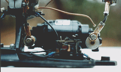
The 1" diameter eccentric wheel on the left (inner) controls the
horizontal sweep of the beam whereas the 1-1/4" diameter wheel on the
right (outer) controls the vertical motion of the light beam. This is the
situation for a vertically mounted unit on the locomotive. For a horizontal
mounting, the situation is reversed. Reference to the "outer" and
"inner" eccentric wheels are made in the following discussion.
Adjustments to obtain the various beam patterns were made by bumping the motor
to get the inner wheel to the points (2) where the bulb plate would be level
horizontally. The outer gearbox was removed via the 3 screws on the Bodine
motor (these are nuts on the "Mars" motor), and the outer wheel
rotated at selected settings and reassembled to the motor. The linkage was
lengthened or shortened make the plate level at this setting. The mechanism was
bench tested with back mounting plate horizontal (In other words, if bulbs were
in place, beams would be directed upwards.) upwards
Horizontal
Mars dual units in ALCOs:
The NKP did have a few (I think low-nose, #865 - #873; and two high-nose, #874 & #875) ALCo RS-36's. The low-snouts came with the horizontally-mounted dual clear lights, as did one lone C-420 (#578). When they got around to ordering EMD GP30's, the oscillating lights were back up between the numberboards in the vertical orientation, and the dual sealed-beam headlights were on the nose horizontally. One possibility is that these were put on without consideration of the pattern, and since these last low-nosed ALCo's were on the property before the GP30's, maybe somebody in the operating department figured it out in between the orders. Still, that C-420 was delivered after the first NKP GP30, so maybe no one ever cared (or noticed) that things were not working right. Based on the use of Mars lights (not Gyralites) in the two high-nosed (passenger service) NKP RS-36 units, I don't think the Gyralite was probably ever contemplated, as that would foul up the materials/mechanical department and rock the boat.
Griff
Hamilton
If the wheel and linkages are adjusted for the �headlight position� down the centerline of the tracks and a symmetrical pattern on both sides of this centerline, the following pattern is possible:
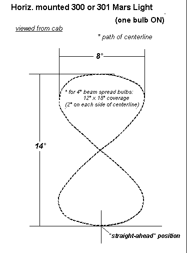
Many patterns are possible with the Mars 300/301 units. The following patterns were achieved with the back of the mechanism on the floor and projecting to the ceiling:

Notice the switch in direction as the pattern emerges out of the collapsed �U� state.
The mechanism:
The following is the way I aligned the light based
on many projections of the beam pattern using laser pointers that were placed
in the center of the bulb openings in the bulb plates using supports. The
pattern desired would be one in which there was the "straight ahead"
parallel to the tracks position at dead center and one that allowed a dip on
either side to illuminate areas below grade as was promoted in literature on
these lights. The patterns for a vertical installation of the light in which
the motor is at the TOP or BOTTOM of the light unit proved to be similar. The
light I used in this beam testing had an outer threaded linkage rod that only
left a few threads on each end to be screwed into the rod end bearings in order
to get the 4-3/4 inch (motor at bottom) length. This unit was most likely mounted
with the motor at the TOP. This was probably done for the convenience of input
of wiring into the light case in order to get to the terminal board at the end
of the unit opposite the motor. This bulb plate was symmetrical. It has a
threaded hole in the boss at each end to which the outer linkage rod end
bearing was attached. The one possibility of the 2 bosses with the threaded
holes would be to have both the sealed beams mounted with the arrows pointing
upwards. This seemed to be the convention. (The Oscitrols, however had one
arrow pointed up and the other down.) The plate could be rotated 180� to
accommodate the upward directed arrows, if desired.
The following
technique was used with a motor having a field winding in series with the
brushes (Bodine motor), making one direction of rotation, regardless of the
polarity of the supply. In this case the brushes were nearest to the END of the
light. Facing the side of linkage attachment to the gearboxes, both wheels
rotated counterclockwise.
It should be
noted that a unit having a motor with a Mars tag will have its own unique
linkage lengths. The output shafts of the gearboxes on these motors are below
those of the Bodine motors.
1) The motor supply leads are found on the
terminal board for energizing the motor directly.
2) The voltage to the motor can be decreased
to 24 VDC, which will help in getting the desired settings. A speed control
(pulsed) would also be most advantageous.
3) The linkages to the motor are disconnected
from both the bulb plate and mid section.
4) The inner
threaded linkage is adjusted to a length of 3-3/4" (center to center of
bearing ends). If the motor is to be at the TOP, adjust the outer linkage to
3-3/4". With the motor at the BOTTOM, the linkage should be close to
4-3/4". [Undergoing the testing for the plate being level will mean some
deviations from these values. For the "motor at TOP" evaluation, a
final value of both linkages (center to center of bearing) was 3-5/8".]
5) The linkages
are both reconnected. These linkages are positioned so that the center of
curvature of each of the bends in the threaded rods are pointing towards the
opposite linkage [i.e. the bends of the rod protrude outward]. (see 10
below)
6) By turning the
motor ON and Off, the following settings are found: The right and left maximum
swings are measured from the light mechanism base to the middle of the bolts
through the upper DSP4 bearings on each side of the support. These must be
equal and at the minimum value. A value close to 4-7/8" should be read.
The motor is "inched" to get equal minimum values on both sides of
the light using the base of the mechanism and the center of the bearing bolts
as a reference. An equal value close to 5-3/16" should be read on each
side at the center position (between the 2 right and left minimums). This
position should also coincide with the inner gearbox wheel having its linkage
attachment towards the other gearbox at the other end of motor.
7) The base of the
mechanism is carefully leveled in both directions using hand level(s) and
shimming up the base to accomplish this. A level placed on the mid section of
the bulb plate parallel to the upper pair of DSP4 bearings should show the bulb
plate as level in this direction.
8) The outside
linkage to the bulb plate is disconnected.
9) The other
(outside) linkage is adjusted by first deciding if it is desired to have the
motor at the bottom of the light or at the top. The 3 screws attaching the
outer gearbox to the motor are unscrewed and the gearbox is allowed to be retrieved
(worm gear and worm disengaged) so that the wheel to which the linkage is
attached may be rotated.
In the following, it should be noted that
"OUTER" refers to the side that is opposite to the center of the
light mechanism. whereas "INNER" refers to the side that is closest
to the center of the light mechanism.
Motor at TOP
The center of the
gearbox wheel and the center of the bolt through the linkage rod end bearing
(to which it is attached) should be brought into place at near the highest
point (towards bulb plate) on the wheel so that both are on a vertical axis
perpendicular to the mechanism base. In order to have a "dip" below
the headlight/track centerline position, the OUTER edge of the 3/16"
gearbox shaft is lined up with an OUTER flat surface of the 7/16" hex bolt
securing the linkage to the eccentric offset on the gearbox wheel. The hex bolt
is ABOVE the gearbox shaft. Having the bulb plate level at this position
assures that there is a downward plunge at the highest point of travel on the
wheel.
Motor at BOTTOM
The center of the
gearbox wheel and the center of the bolt through the linkage rod end bearing
(to which it is attached) should be brought into place at near the highest
point (towards bulb plate) on the wheel so that both are on a vertical axis
perpendicular to the mechanism base. In order to have a "dip" below
the headlight/track centerline position, the INNER edge of the 3/16"
gearbox shaft is lined up with an INNER flat surface of the 7/16" hex bolt
securing the linkage to the eccentric offset on the gearbox wheel. The hex bolt
is BELOW the gearbox shaft. Having the bulb plate level at this position
assures that there is a downward plunge at the highest point of travel on the
wheel.
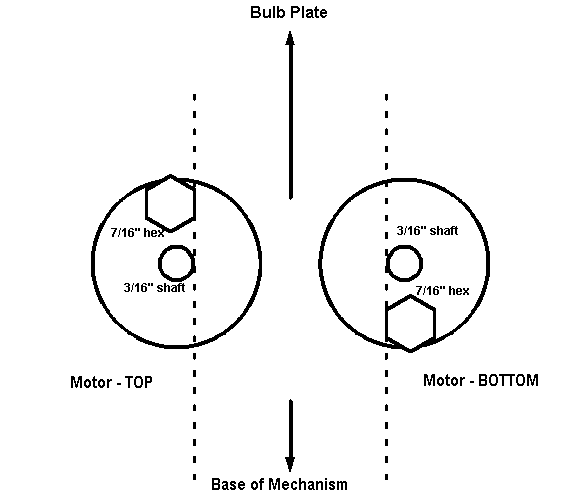
The gearbox is reinstalled and position of
wheel rechecked.
10) The linkage is
reconnected to the bulb plate. One thing to make sure that on operation, the
rod end bearing attached to the gearbox wheel doesn't rub against this wheel.
The threaded linkage rod is tightened into position (locking nuts) so the curve
center is toward the center of the light. [i.e. the bend of rod is protrudes
outward, away from the middle of the light]. The linkage may be also rotated
slightly - away from the gearbox wheel to avoid the contact of this end with
the aluminum wheel. This may have been a problem with the longer 4- 3/4"
lengths (motor at BOTTOM). The 3-5/8" lengths (motor at TOP) seem to be
less critical in this adjustment.
11) With everything
in its leveled up position, a level is placed across the long axis of the bulb
plate. The threaded rod is adjusted to whatever will make the bulb plate level.
12) The motor is
allowed to run and all should be rechecked for the bulb plate being level in
both directions and that the conditions of the outer gearbox wheel shaft
center/linkage bolt center are in correct alignment as above. There are 2
positions on the inner wheel in which the bulb plate should be level in both
directions. These should coincide with the selected position on the outer
wheel. If there is a discrepancy, this should be corrected by rechecking for
midpoint level position (see 6 above). This is critical due to producing
the desired beam pattern. The outside gearbox wheel is positioned in a way
which allows for a dip of the bulb plate below the leveled position that was
attained above. This was a promotion of the light in being able to illuminate
areas on each side of the track below grade
The selection on
the "best" pattern and method of obtaining this pattern is based on
what may have been the desired pattern. No literature seems to have any
specifications for the "best" pattern or any way of setting this
pattern on the light unit. It should also be noted that there are other positions
on wheel that could be set for a similar pattern, but the positions selected
was the most easy to reference for the critical setting.
___________________________________________________