
HO MODULE SPECIFICATIONS
Revision 2
April 2000
Table of Contents
GENERAL DESCRIPTION
General
Scope
Club Modules
TRACK WORK FOR BASIC MODULEFRAMEWORK FOR BASIC MODULE
Side and End Frames
Deck
Assembly
General Dimensions
Caring Handle
Painting
Module Mating
Legs
Fascia Board
WIRING AND CONNECTIONS
General
Wiring Diagram
Through Track Connections
Inter module Connections
Power Pack Connections
Insulating Gaps
Mainline Crossover
Walk Around Throttle
SCENERY
General
Ground Cover
Clearances
Elevations
Sky board
Telephone Poles
South of Mainline
Mainline Ballast
List of Figures
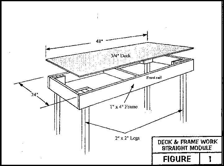
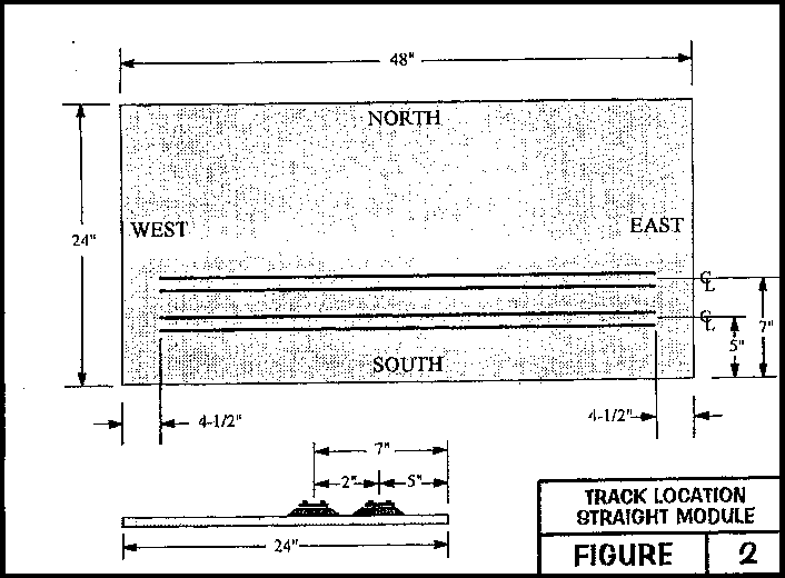
Figure 1 - DECK AND FRAME WORK - STRAIGHT MODULEFigure 2 - MAINLINE TRACK LOCATION - STRAIGHT MODULE
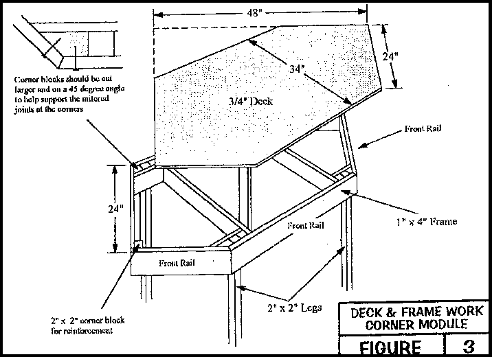
Figure 3 - DECK AND FRAME WORK - CORNER MODULE
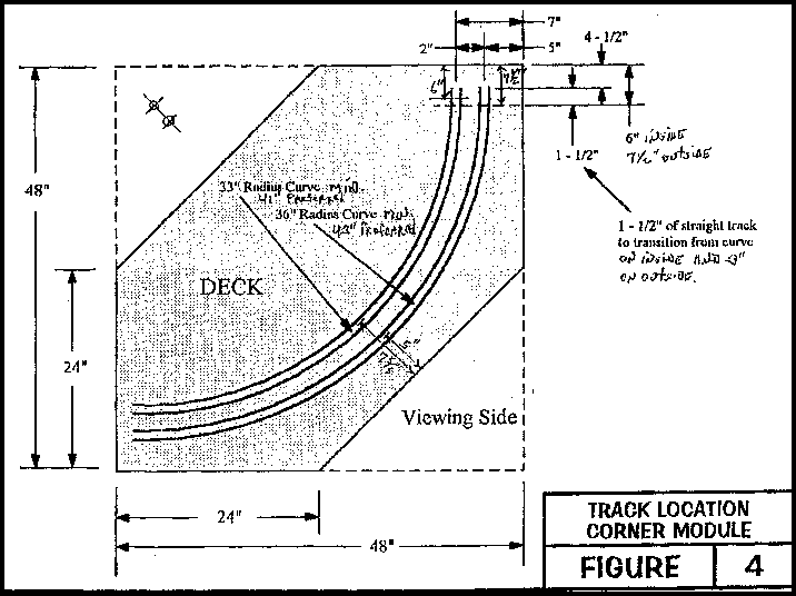
Figure 4 - MAINLINE TRACK LOCATION - CORNER MODULE
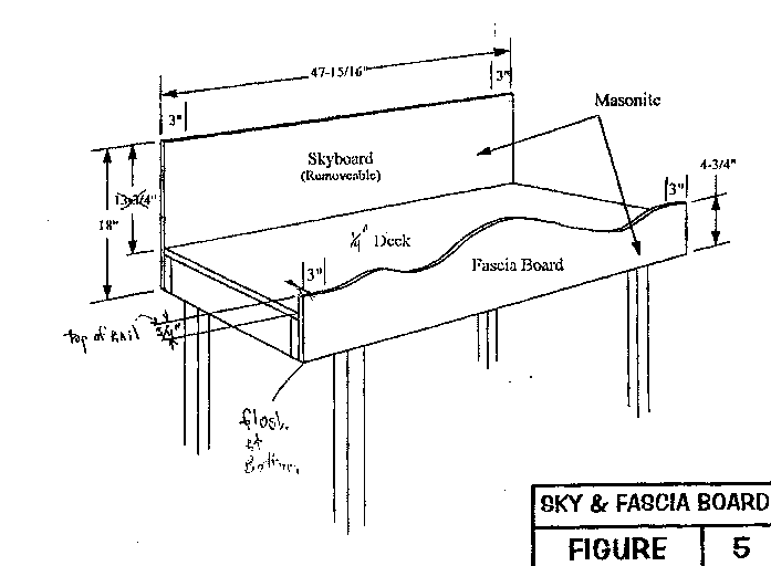
Figure 5 - SKY & FASCIA BOARDS
Figure 8 - WIRING SCHEMATIC
GENERAL DESCRIPTION
General
The modular concept is such that members can each build relatively simple, portable sections which can be combined in any arrangement and number to form a larger operating layout. All basic modules are interchangeable in any location on the layout. The module can be quickly and simply connected, or disconnected to other modules. They can be a basis for a permanent layout and can allow for a wide range of individual expression, from simple to complex track and minimal to full scenery.Scope
Each module should meet the following goals as a minimum, in order to provide the inter changeability necessary to allow the modular concept to work. Each module should adhere to all of the standards presented within this specification. The modules must be fully portable, relatively equal in size and be constructed of readily available materials to minimize expense and provide for ease of manipulation. The track work should consist of large radius curves with two mainline tracks that will result in two continuous loops for two train operation without interference or overseeing required by the operators.FRAMEWORK FOR BASIC MODULESince the features described above require uniform standards of construction in order to operate interchangeably, the following sections provide the details of these specifications. Any deviations to the specified standards will require the approval of the standards committee, before the module will be permitted to be used in the club layout. By specifying and following these standards, we can provide a basic foundation for all models to share their particular skills and interests, while maintaining a loosely organized structure that everyone can live with.
Club Modules
The Club may purchase specific modules from time to time if the member who owns that module anticipates leaving the club. Specific modules are defined as those integral to the Club's theme for the overall layout. The maximum the club will pay for the module is the cost of materials that were put into the module.
General
The intent of the modular concept is such that each module will mate with all others. Each module must conform to the dimensions and standards provided herein.
Side and End FramesThe frames should be constructed of 1x4 nominal lumber, such as common pine. The boards should be straight, solid, free of excessive knots and will be sanded smooth.
DeckThe deck can be constructed of any materials that equal a composite total of 3/4". This must consist of material that will provide strength to the module surface, as well as provide the type of surface needed for the particular module scenery concept. For example, the deck could be a single piece of 3/4" plywood, good one side (AC). It could also consist of a 1/4" piece of plywood that has 1/2" homosote glued and screwed to the top. The deck could also be a combination of plywood, foam, homosote or other materials. The intent is to provide a solid (not open grid) bench top that will stand up to the forces involved with frequent moving, adjusting and disassembling of the modules. The pre assembled modules will come with a deck of 1/4" Luan plywood, as a base.
Assembly
The deck and frames are to be joined with glue and screws to provide strength during movement.
General Dimensions
The height of the frames and deck will be 4", +/- 1/4". The module will be a minimum of 24" wide and 48" long, and the module must be square. Any deviations to these dimensions will require approval of the standards committee.
Carrying HandleA drawer handle, or hinged tool box handle, on the rear side of the module is optional. The use of such a handle will make carrying the module easier.
Painting
All visible surfaces of the module, when it is assembled, will be painted a semi gloss black.
Legs
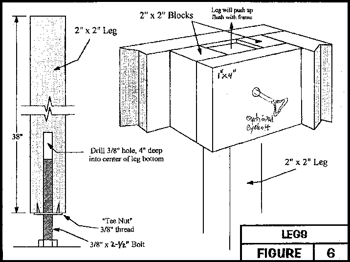
Each module is to have four (4), removable, 2x2 legs. Legs must have 3 1/2" long adjustment bolts, as shown in Figures 1, 3, 5 and 6, to allow for a total of 2" of leveling. With the adjustment bolt 1" out, the measurement from the floor to the top of the mainline rails is to be 40". With the deck and rail heights previously described, this necessitates a leg length of 38". The legs will be positioned as depicted in Figures 1 and 3, for both side and corner modules. The legs will fit into pockets in each location, as shown, and will not require additional attachment to the module when being used in a club, interconnected layout. If any additional leg attachment is desired, an eyebolt through a hole drilled in the leg pocket and leg can be used.
Facsia Board
A masonite fascia board will be provided on the front of each straight module and on the three front sides of each corner module, as shown in Figure 5. The top of the fascia board will be at the same height as the top of the mainline rails (40" from floor) at each end of the module, for a distance of 3" on either end. The area in-between these points can accommodate any fascia height required to effectively blend into the overall scenery of the module. The fascia board will only be fastened to the side frames of the module, using flat head screws. These screws and attachment areas will be covered by the skirting used around the front of the modules.
TRACK WORK FOR BASIC MODULE
Track
The mainline track will be Atlas brand (#168), nickel silver, Code 100, flex track with black, plastic ties.
Turnouts
The mainline turnouts will be Atlas nickel silver #6 (model #283 LH and 284 RH). Number 4 switches and other brands are optional for non mainline turnouts. All turnouts must be wired to give dependable electrical and mechanical performance. The mainline turnouts will be fitted with Atlas manual or remote switch machines (manual = Atlas #62 and 63, remote = Atlas # 52 and 53).or Caboose Ind Manual Ground Throws.
MainlinesTwo mainlines, on Midwest #3013 cork roadbed, with location dimensions as shown in Figures 2 and 4 will be provided as a minimum on each module. The mainlines can be curved or straight, but the last 3 1/2" of each end of the mainlines must be straight and parallel to the front edge of the module, centered at 5" & 7" from the front edge of the module. Each track will end 4 1/2" from the extreme edge of the module to allow for connecting tracks and rail joiners. A crossover between mainlines, using the previously mentioned #6 switches, is optional. If installed, the crossover must have insulating rail joiners on both rails. Any deviations from these specifications must be obtained from the standards committee.
For mainlines on corner modules, the above standards will apply, except that the last 1 1/2" of the inside mainline and 3" of the outside mainline will be straight before the 4 1/2" space required for connecting tracks is encountered. Refer to Figure 4 for the corner module specifications.
Branch LinesBranch lines are optional on all modules. If used, they must conform to these track, switch and wiring standards, and all branch lines will be insulated from the mainline track, using plastic rail joiners on both rails. The exception to the standards for branch lines is that these lines do not require the use of cork roadbed if desired.
Route Convention
Facing the module, with the two mainlines closest to you, the mainlines run East (to the right) and West (to the left), with North being on the rear of the module and South being on the front edge of the module. Refer to Figure 2 for this nomenclature.
Minimum RadiusMainlines will have a minimum radius of 33". Branch lines will have a minimum of 18". Any deviations will require approval form the standards committee.
ClearancesAll clearances must conform to those dictated by a standard NMRA HO Track Gauge. The track center line, for branch line tracks in front of the mainline, Eastbound track, will be a minimum of 3" from the outside edge of the module to prevent equipment from falling to the floor if a derailment should occur.
Switch MachinesSwitch machines are required for all mainlines turnouts and are to be as specified previously. All other turnouts are to have positive locking switch machines, whether they are manual or electric, under table or above.
Module Connector TracksThe mainlines will be connected from one module to the next be use of a standard 9" piece of snap track, Atlas brand nickel silver with black plastic ties, model #821. It is optional to use 9" snap track rerailers. If used, these must be Atlas #844
The rail joiners used at the module connections should be arranged so that they can be pushed all the way back on the mainline, such that the connector tracks can be dropped in and then the rail joiners pushed onto the connector tracks. This will necessitate the mainline track ends' ties being modified to allow the rail joiners to be pushed backwards.
Uncoupling RampsAll uncoupling ramps located on the mainline, must be KD, electromagnetic type, #307.
WIRING AND CONNECTIONS
GeneralEach module will provide through connections and outlets for variable DC track power. Each module will have the mainline tracks wired for interchangeable operations. The interconnected layout is designed to be operated from a single location, but each module can have a power pack with provisions to mount and connect it, to provide power for branch line operations.
Wiring Diagram
Refer to Figures 7 and 8 for all wiring specifications for standard modules.Through Track Connections
In order to provide through track connections from module to module, two 4 position/8 screw terminal connectors will be mounted on the inside, back rail of each module. These terminal connectors will be Radio Shack part number 274-658, or equivalent. The terminal connectors will be on the NE and NW corners of the module, as shown in Figure 4.
The purpose of the terminal strips is to provide power to the mainlines from power packs other than the central one, as might be used for single module operations. Additional terminal strips may need to be mounted to provide power connections for branch line operations. If this is the case, then the terminal strips will be the same style as the mainline ones and will be located sufficiently away from the required mainline ones so as to not be easily confused with the others. Adequate labeling is required for all terminal connections.
Mainline through (buss) wiring will be 16 gauge, four color hookup wire, adhering to the color conventions presented below. Track drops to the 16 gauge wires may be of a smaller gauge wire, but no less than 22 gauge (Bell type) wire.
TRACK CONNECTION COLOR
- South Rail, South Mainline (closest rail to front edge) RED 1
- North Rail, South Mainline GREEN 2
- South Rail, North Mainline BLUE 3
- North Rail, North Mainline (farthest rail from edge) WHITE 4
1. Use different colors from the above wiring scheme for all branch line track wiring.
2. The terminal screw numbers
are from left to right while looking at the front of the terminal strip
(i.e. #1 is on the left, #4 on the right - see Figure A, below)
FIGURE A
The mainline buss wires will be connected to the terminal strips by use of open end spade connectors that are either crimped or crimped and soldered to the wires.
Inter Module ConnectionsEach module will provide a 2' long, 4 wire, 16 gague connector cord with open end spade connectors on one end and RCA jacks on the other end. The RCA jacks will be male on the left (facing the front of the module) and female on the right.
PowerPack Connections
Mainline tracks will be powered from 2 centrally located DCC power modules that will utilize the under table wiring and plug connectors to provide power to all mainlines. The mainlines may be powered by using the terminal strips when the modules are being used individually.
Branch line tracks will be powered by connection with the mainline power buss to which the track is connected. The branch line terminal strips and the black and white wiring conventions described above will be used. The branch line electrical connection shall include a double pole switch which will electrically isolate the branch line tracks.
Insulating GapsAll insulating gaps must be filled to preserve gap and gage. If insulated rail joiners are used, they must be painted to match the color of the rails.
Mainline Crosover
It is recommended that crossovers be used when possible. These must have insulating gaps to isolate the two mainlines from each other.
Walkaround ThrottleDCC Digitrax UP3 Throttle connectors shall be installed on each corner module and one module for each yard configuration.
SCENERY
GeneralThe overall design, motif and scenic details are optional to each module builder. Each module can be designed as a diorama in itself, or it can be planned to merge with other modules in the layout at the discretion of the module builders. However, to provide continuity and inter changeability, there are some required standards for scenery.
Ground CoverAll grass, ground and foliage will be in appropriate shades, with no bright colors of toy like appearance.
ClearancesAll clearances for buildings, bridges, scenery, etc., will conform to the NMRA HO Standards Gauge as the ruling factor.
ElevationsThe mainline is to be level - there will be no change in grade on the mainline. Branch lines may vary in grade.
Skyboard
Each module will have a removable sky board that extends up 13 3/4" above the module surface, trimmed to avoid interference with adjoining modules. Each sky board will be 1/8" Masonite and will be painted with a sky blue paint, using Martin Semour, interior latex flat, Twinkle Blue (158-7 WW). The rear edge scenery will be blended into this neutral sky background as appropriate. On non standard depth modules (greater than 24") a transition sky board will be used to meet the sky boards of the adjoining modules. Refer to Figure 5 for a view depicting this arrangement. Sky boards should be contoured to the scenery with a 3" transitioning section on each end that will be flat at the 13 3/4" level above the surface.
Telephone PolesIf telephone poles are used along the mainline, they will be placed 4" from each end of the module and at 8" spacing across the length of the mainline on the North side of the mainline tracks.
South of MainlineStructures along the outboard side of the modules must be complete or the surface facing the public must consist of a section of the fascia board, painted a solid black color. All unsceniced, exposed surfaces must be painted semi gloss black.
Mainline BallastThe mainline tracks will be ballested using Woodland Scenics Gray Blend, Medium #B94.
Return to Piedmont
Railroaders home page