This is a detail guide dedicated to a Standard Model 2-200. The photos are of LIRR W-93, now owned by the Twin Forks Chapter, NRHS.
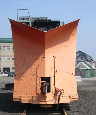
This is the very front of the machine, looking head on at the nose plow.
These are the adjustable shoes that are the actual part that rides the top of the railhead. To the left is where another
cutting blade would mount but it is not on this machine anymore.
The bottom center of the nose plow.
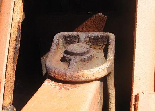
Front drawbar, The front coupler was removable, thus a large pin held it in place.
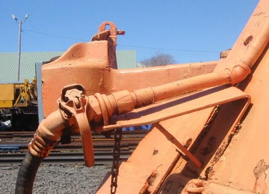
Front left, The bracket that held the air hose and angle cock in place.
Moving back to the left, This is the small blade, attached to the front plow. This kept debris from getting up in back of the wing or by the trucks.
Looking behind, this is the cable that raised and lowered the rear end of the front plow.
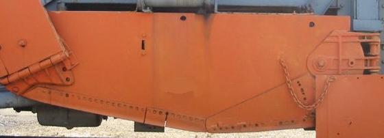
Right side main wing. Note the chain to hold the rock gaurd back and the movable ballast cutter section.
This is the air cylinder that operated the bank sloper.
This is the actual bank sloper wing that would be used in ditching or carry wing form ( see operations page ).
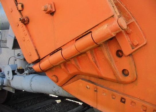
A detailed view of the bank sloper hinge.
The rear of the bank sloper showin gthe air line for the lock and the hinges.
This is the air lock for the bank sloper behind the wing. Also seen is the air line for the rear most horizontal brace, and the steel pin to keep the bank sloper
from moving in transportation.
A rear view of the diagonal brace. The metal piece sticking up was a bracket that held a small rope hoist for setting up the carry wing brace.
The air cylinder on the diagonal brace. Note the 2 different hose sizes, the air lock is 1/2'' the cylinder is 3/4''.
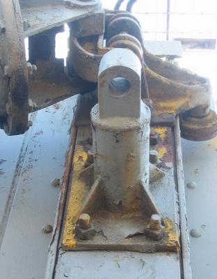
The bracket that once held the carrier wing brace.
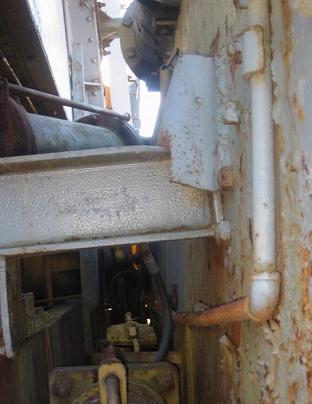
This is the modified I beam that the wing rests on when not used.
Looking over the rear deck, showing the air tank.
Plumbing on the air tank. This includeds a water seperator, the pipe leading to the left on the very bottom goes to the manifolds.
Standard Miner handbrake.
Brake gear looking to the front.
Brake gear looking towards the rear.
Brake Valve.
70 ton trucks, although rebuilt with roller bearings.
Rear left of the machine.
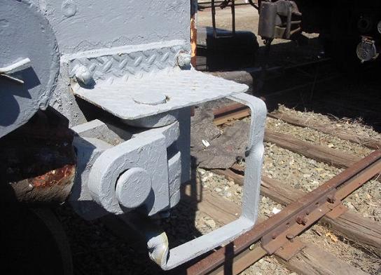
Rear steps.
Rear of the spreader, the right hose is for the air tank ( main res. equilizing ) and the left one is the brake pipe.
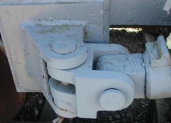
One of the double pivot hinges on the braces.
Air lock showing the lock, the air blower pipe and under the cover to the right is a cogged wheel.
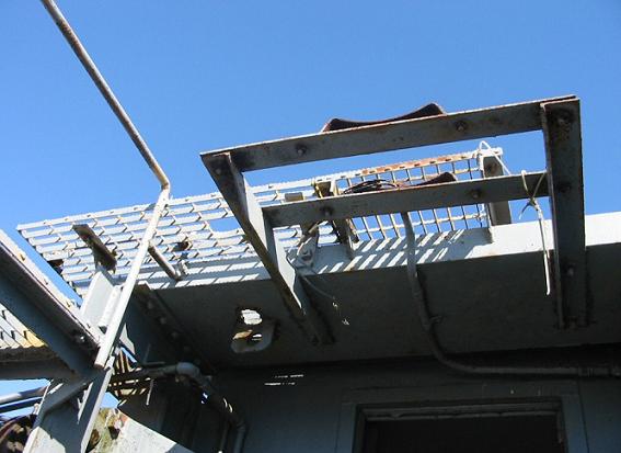
Front headlight bracket.
The left front crosshead, the yellow piece is mounted directly to the plow.
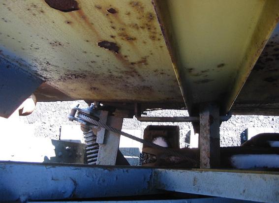
Looking down the left side of the plow.
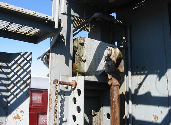
Right side verticle post, the pin is what the head of the vertical post rests on and is adjustable.
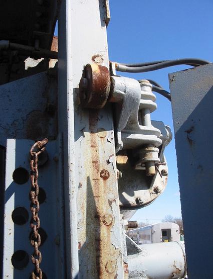
Bracket on the vertical post that holds the diagonal brace.
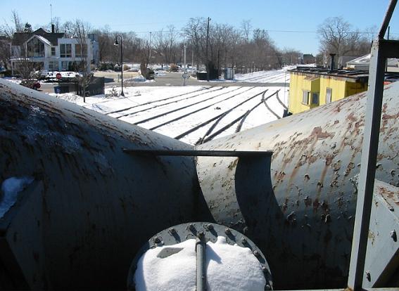
The view looking foward from the cab.
Left hand operating manifold looking towards the front.
Left hand operating manifold looking towards the rear.
right hand operating manifold looking towards the rear.
The foot pedals that control the air locks.
Air gauge on the rear of the manifold also showin gthe heater, mounted where the carrier wing control was.
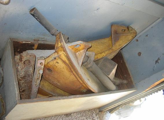
A box in the front of the spreader cab holding rerailers and spare parts.
More to come in the future.....